CALORIQUE Snow & Ice CM1020 User manual

Installation Manual
Snow & Ice Melting
Loading Dock
Skid Plates
CCMM11002200- 04-08-13

Junction Box
Before Installing
•Failure to follow installation instructions, or misapplication, may
result in electrical shock, fire and/or personal injury hazard.
•Installation must conform to all requirements of the National
Electrical Code NEC) 426.23 B) Fixed Outdoor Electric
Deicing and Snow-Melting Equipment) and any local codes or
ordinances. In countries other than the USA, follow the dictates
of the local electrical and building code.
•The electrical source must conform to the heating units’ require-
ments voltage and circuit amperage capacity) and overcurrent
protection device must incorporate a GFCI.
•Connection of heating unit s) should be performed by a
licensed electrician.
•Do not cut, bend or otherwise alter the CalorIQue Heated Skid
Plate. Any alterations to the units may present a shock or fire
hazard.
•Suitable overcurrent protection shall be provided by means of
circuit breaker or fuse. Overcurrent protection shall be of a type
indicated as being acceptable for branch circuit protection.
•WARNING: Ensure that adequate drainage is provided for
water runoff.
Tools & Materials
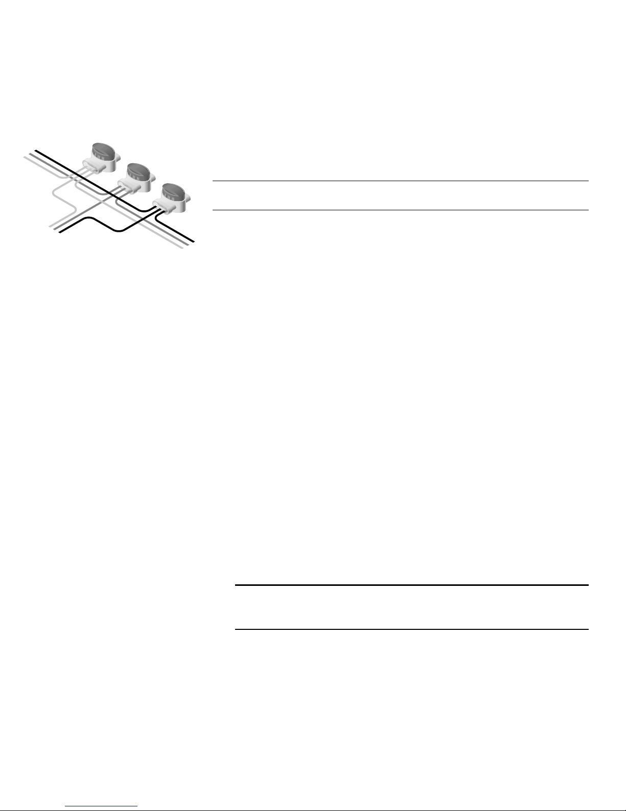
•CalorIQue Heated Skid Plate See Free Estimate Worksheet
CM1012) for ordering details.
Typical heated skid plate. Your model may vary.
•Standard Electrical Hand Tools
•Overcurrent Protection User / installer supplied. The circuit
breaker used with this sistem must have an overcurrent rating
of 30 amps and an integral GFCI rated for 30mA equipment
protection.
•Electrical Conduit Rigid or flexible conduit meeting the
requirements of N.E.C. 426.23 B) of local code e.g. carflex).
•Electrical Wire Suitable wire for use within exterior conduit.
Three conductors must be available. Conductors may range
from #14-22 AWG, size based upon total ampacity connected.
•Drill with Bits Bit must be rated for drilling into the material
onto which the skid plate s) is being installed.
NOTE: If using an anchoring method other than the supplied expan-
sion shields and stainless steel screws, follow the manufacturer’s
instructions for best results. In all preparation and installation steps
indicating use of the expansion shields and supplied 1/4” stainless
steel screws, replace with the anchor manufacturer’s instructions.
•Construction Adhesive This adhesive must be water and heat
resistant.
Non-Skid Sur ace

•Silicone Sealant Exterior grade silicone used to waterproof the
junction box cover plate.
•Control System. Supplied by CalorIQue, automatically turns
the system on and off based on the temperature and presence
of precipitation. UL Listed and CSA Certified.
•Specification Sheet. Provides specifications for all skid plates
included with the system.
•Product Labels. Provide information about the system that
may be required during future remodeling or repairs.
•Warrantee Card This card must be filled out and returned to
CalorIQue to ensure proper registration of the warrantee.
Typical system wiring layout.
Preparation
•If necessary, level worn or damaged loading docks with quick
setting leveling compound.
•Install and supply power to a junction box located conveniently
for connection to the CalorIQue Heated Skid Plate s). Make
sure that power is turned off at the distribution panel before
installing this system.
•Install control system according to the separate instructions.
•Using an accurate ohm meter, test each skid plate to ensure
that it is within the limits shown on the specificatasdfasdfion
sheet.
Installation
•Drill Holes to Accept Expansion Shields
Using the skid plate as a template, mark and drill holes for the
expansion shields.
TIP:Since the exact hole locations may differ from plate to plate, label
each dock area and plate and use the appropriate skid plate to mark
the hole locations.
Place skid plate(s) based on their junction box type, and the type o
railing or edge work.
•Insert the Expansion Shields into the Holes.
•Mount the Skid Plate s). Repeat the following for each plate:
• Apply construction adhesive to the loading dock.
Junction Box
Style B
Junction Box
Style A
Wall or
Railing
Junction Box
Style A
Railing
Skid Plate(s)
Power Distribution Panel
Control Box
Sensors

• Replace the skid plate and secure in place using the supplied
stainless steel screws.
•Wire Skid Plates Together (If more than one plate is used )
Using the supplied tap connectors, wire the skid plates together.
Using the following figure as a guide, route conduit into the
junction box on each plate and splice the three legs of electrical
power together using the supplied waterproof connectors.
Tap wires between each plate using the connectors within the
attached junction box.
•Secure Conduit in Place
Use a recognized method for securing the conduit.
•Attach Cover Plate
Apply a continous bead of exterior grade silicone sealant along
the inside edge of the cover plate, then screw the plate to the
junction box using the included screws.
•Check Resistance Using an accurate ohm meter, test each
skid plate to ensure that it is within the limits shown on the
specification sheet. This test confirms that the plates were not
damaged during installation.
•Complete Electrical Connections
• Connect Skid Plates to the Control System.
Following the manufacturer’s instructions for the control, con-
nect the skid plates to the control.
• Supply Power to the Control.
• Test the System Operation.
Turn on the system and ensure that it is drawing the correct
amount of current. The current draw for your system is listed
on the order sheet that comes with the system.
Operation
NOTE: Do not operate the system when the air temperature is above
50°F 10°C). Operation above this temperature may overheat the ele-
ments and present a shock hazard.
•When using the CalorIQue snow sensor, the skid plates will
heat up automatically when needed. No user intervention
should be required. See the control’s operations manual for
additional information.
•When using an on/off switch as the sole control, turn on the
system when snow or icy conditions are expected.
Copyright © 2002-2004 CalorIQue, Ltd.
All rights reserved.
Printed in USA
CalorIQue, Ltd
2380 Cranberry Highway
West Wareham, MA 02576
USA
+1 508.291.4224 voice
+1 800.922.9276
+1 508.291.2299 fax
www.calorique.com
Line
Line
Ground
To Next
Plate
To Element
(internal)
To Previous
Plate or
Junction Box
This manual suits for next models
1
Table of contents