MI148 REV.10 Page 5 of 3
10.0Ces réchauffeurs sont prévus pour être installés dans une
température ambiante du maximum 40°C.
Pour les elements à gaines métalliques, la
contamination de l'isolation ou l'accumulation
d'humidité peut causer un problême à la gaine
de l'élément générant un arc électrique et
laissant couler du metal en fusion. Installer un
système de fuite à la terre adéquat pour
prévenir des blessures et/ou des domages aux
biens.
11.0Les boîtiers de raccordement à chacune des extrémités
ont un volume de 56 po³(917 cm³) pour OKH et OKD et 12 in3(196
cm3) pour OKB.
12.0Les fils de raccordement doivent pouvoir supporter une
températurede194°F(90°C). Uncâblearmé flexible est fortement
recommandé pour les applications protégées des conditions
climatiques extérieures.
13.0Pour protection de court-circuit, les unités de chauffage
doivent être protégés avec des fusibles à action rapide ou
disjoncteurs dont l’ampèrage inscrit sur la plaque signalitique en
conformité avec le code élecrique local.
Les radiateurs à tube de quartz ou lampe de
quartz doivent être montés horizontalement
seulement. Les radiateurs à tubes métalliques
peuvent être montés en toutes positions
désirées.
14.0Pour le raccordement (tous les appareils, à l'exception du
modèledetypeR),retirerlacanalisationsupérieureafind'yinstaller
le raccord pour conduit et raccorder les fils d'alimentation et de
miseàlaterreauxfilsderaccord. Replacerlacanalisationjusqu'au
prochain service. L'appareil de type R possède un boîtier résistant
àl'humiditéquirecouvrelesterminauxd'unélémenttubulaireformé
en U. Utiliser un conduit rigide (½") pour assurer l'étanchéité.
En faisant les raccordements au radiateur, NE
TIREZ PAS les fils d’alimentation du couvercle.
Tirer les fils peut éliminer la boucled’expansion
à la connection du bout de l’élément et peut
endommager l’isolation des fils.
15.0Suivre la procédure ci-après, réf. Fig. 2, pour un tube ou
lampe de quartz lors de l'installation:
15.1Débrancher l'alimentation principale.
15.2Retirerlescouvercles des boîtiers de terminaison aux deux
extrémités de l'appareil.
15.3Retirer la vis d'ancrage sur un des supports de retenue et
glisser le support de céramique de l'élément de côté.
15.4Faire passer le fil d'alimentation de l'élément dans le trou
du support de céramique à l'extrémité fixe en premier lieu. Glisser
le support de céramique (retiré au par. 15.3) par dessus l'élément,
de telle sorte que l'élément est maintenant contenu entre les deux
supports de céramique et revisser la vis d'ancrage.
15.5Dévisserlégèrementlavis du terminal électrique sur le bloc
de céramique pour exécuter le raccordement de l'alimentation
électrique.
15.6Pour raccorder le fil de l'élément, glisser les supports de
céramique aussi loin que possible vers le centre de la fixture et
boucler le fil de l'élément au terminal électrique en laissant très
peu de jeudanslefil. (Veuilleznoterquelessupportsdecéramique
sont conçus pour glisser librement lors de l'expansion thermique
de l'élément et les fils de raccord 'tendus' permettent de retenir
l'élément en position).
15.7Raccorder les fils d'alimentation aux terminaux électriques
et remetter en place les couvercles des boîtiers de terminaison.
15.8Avant de mettre sous tension, essuyer la gaine de quartz
et le réflecteur à l'aide d'un linge imprégné d'alcool.
OPÉRATION
Pour les éléments à gaines métalliques, vous
devez en premier lieu effectuer une lecture de
la résistance. Les éléments n'atteignant pas
1M
Ω Ω
Ω Ω
Ω
doivent passer par une procédure de
sèchage. Veuillez s'il-vous-plait consulter le
fabricant pour les détails sur la procédure à
suivre si l'élément a moins de 1M
Ω Ω
Ω Ω
Ω
.
16.0Serrer la vis de réglage dans la pièce coulée d'extrémité
(une extrémité seulement) après avoir installé le radiateur et avoir
réglé l'angle d'inclinaison horizontale. Cette vis doit être serrée
même si le radiateur n'est pas incliné
17.0Mettre l'appareil sous tension à la tension indiquée sur la
plaque signalétique et vérifier visuellement si l'élément glisse
librement dans ses supports lorsqu'il prend de l'expansion. (Un
léger fléchissement au centre de l'élément est normal tout
spécialement sur les appareils de longueurs importantes.).
18.0Les radiateurs, avec éléments tubulaires métalliques, qui
n'ont pas été en opération pour une période prolongée, doivent
êtreremis en opération sous surveillance pourlespremières trente
minutes.
MI148 REV.11 Page 2 de 3
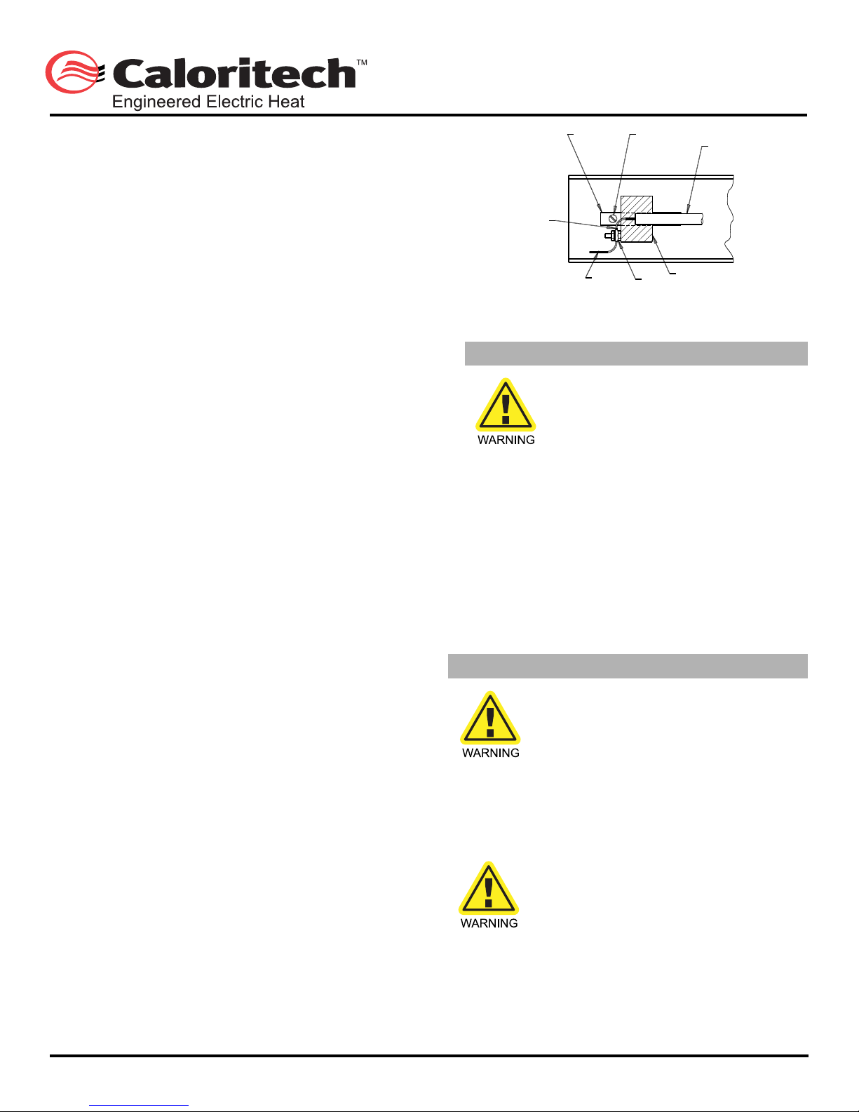
FIG. 2 –INSTALLATION ÉLECTRIQUE POUR
RADIATEUR DE QUARTZ
FIL DE L’ÉLÉMENT
DOIT SE TERMINER
AVEC TRÈS PEU
DE JEU
TUBE OU LAMPE DE
QUARTZ
TERMINAL
ÉLECTRIQUE
FIL
D’ALIMENTATION
SUPPORT DE
RETENUEVIS D’ANCRAGE
SUPPORT DE CÉRAMIQUE DE L’ÉLÉMENT
MC
Chauffage électrique sur demande
CCI Thermal Technologies Inc. 2721 Plymouth Drive, Oakville, ON L6H 5R5 Tel. (905) 829-4422 Fax (905) 829-4430
www.ccithermal.com
MI148 REV.11.01
MI148 REV.10 Page 5 of 3
10.0Ces réchauffeurs sont prévus pour être installés dans une
température ambiante du maximum 40°C.
Pour les elements à gaines métalliques, la
contamination de l'isolation ou l'accumulation
d'humidité peut causer un problême à la gaine
de l'élément générant un arc électrique et
laissant couler du metal en fusion. Installer un
système de fuite à la terre adéquat pour
prévenir des blessures et/ou des domages aux
biens.
11.0Les boîtiers de raccordement à chacune des extrémités
ont un volume de 56 po³(917 cm³) pour OKH et OKD et 12 in3(196
cm3) pour OKB.
12.0Les fils de raccordement doivent pouvoir supporter une
températurede194°F(90°C). Uncâblearmé flexible est fortement
recommandé pour les applications protégées des conditions
climatiques extérieures.
13.0Pour protection de court-circuit, les unités de chauffage
doivent être protégés avec des fusibles à action rapide ou
disjoncteurs dont l’ampèrage inscrit sur la plaque signalitique en
conformité avec le code élecrique local.
Les radiateurs à tube de quartz ou lampe de
quartz doivent être montés horizontalement
seulement. Les radiateurs à tubes métalliques
peuvent être montés en toutes positions
désirées.
14.0Pour le raccordement (tous les appareils, à l'exception du
modèledetypeR),retirerlacanalisationsupérieureafind'yinstaller
le raccord pour conduit et raccorder les fils d'alimentation et de
miseàlaterreauxfilsderaccord. Replacerlacanalisationjusqu'au
prochain service. L'appareil de type R possède un boîtier résistant
àl'humiditéquirecouvrelesterminauxd'unélémenttubulaireformé
en U. Utiliser un conduit rigide (½") pour assurer l'étanchéité.
En faisant les raccordements au radiateur, NE
TIREZ PAS les fils d’alimentation du couvercle.
Tirer les fils peut éliminer la boucled’expansion
à la connection du bout de l’élément et peut
endommager l’isolation des fils.
15.0Suivre la procédure ci-après, réf. Fig. 2, pour un tube ou
lampe de quartz lors de l'installation:
15.1Débrancher l'alimentation principale.
15.2Retirerlescouvercles des boîtiers de terminaison aux deux
extrémités de l'appareil.
15.3Retirer la vis d'ancrage sur un des supports de retenue et
glisser le support de céramique de l'élément de côté.
15.4Faire passer le fil d'alimentation de l'élément dans le trou
du support de céramique à l'extrémité fixe en premier lieu. Glisser
le support de céramique (retiré au par. 15.3) par dessus l'élément,
de telle sorte que l'élément est maintenant contenu entre les deux
supports de céramique et revisser la vis d'ancrage.
15.5Dévisserlégèrementlavis du terminal électrique sur le bloc
de céramique pour exécuter le raccordement de l'alimentation
électrique.
15.6Pour raccorder le fil de l'élément, glisser les supports de
céramique aussi loin que possible vers le centre de la fixture et
boucler le fil de l'élément au terminal électrique en laissant très
peu de jeudanslefil. (Veuilleznoterquelessupportsdecéramique
sont conçus pour glisser librement lors de l'expansion thermique
de l'élément et les fils de raccord 'tendus' permettent de retenir
l'élément en position).
15.7Raccorder les fils d'alimentation aux terminaux électriques
et remetter en place les couvercles des boîtiers de terminaison.
15.8Avant de mettre sous tension, essuyer la gaine de quartz
et le réflecteur à l'aide d'un linge imprégné d'alcool.
OPÉRATION
Pour les éléments à gaines métalliques, vous
devez en premier lieu effectuer une lecture de
la résistance. Les éléments n'atteignant pas
1M
Ω Ω
Ω Ω
Ω
doivent passer par une procédure de
sèchage. Veuillez s'il-vous-plait consulter le
fabricant pour les détails sur la procédure à
suivre si l'élément a moins de 1M
Ω Ω
Ω Ω
Ω
.
16.0Serrer la vis de réglage dans la pièce coulée d'extrémité
(une extrémité seulement) après avoir installé le radiateur et avoir
réglé l'angle d'inclinaison horizontale. Cette vis doit être serrée
même si le radiateur n'est pas incliné
17.0Mettre l'appareil sous tension à la tension indiquée sur la
plaque signalétique et vérifier visuellement si l'élément glisse
librement dans ses supports lorsqu'il prend de l'expansion. (Un
léger fléchissement au centre de l'élément est normal tout
spécialement sur les appareils de longueurs importantes.).
18.0Les radiateurs, avec éléments tubulaires métalliques, qui
n'ont pas été en opération pour une période prolongée, doivent
êtreremis en opération sous surveillance pourlespremières trente
minutes.
MI148 REV.11 Page 2 de 3
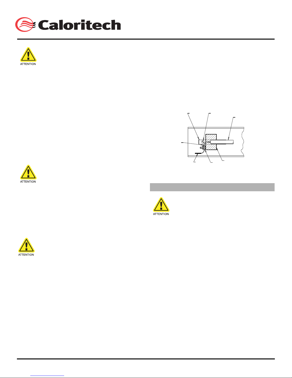
FIG. 2 –INSTALLATION ÉLECTRIQUE POUR
FIL DE L’ÉLÉMENT
DOIT SE TERMINER
AVEC TRÈS PEU
DE JEU
TUBE OU LAMPE DE
QUARTZ
TERMINAL
ÉLECTRIQUE
FIL
D’ALIMENTATION
SUPPORT DE
RETENUEVIS D’ANCRAGE
SUPPORT DE CÉRAMIQUE DE L’ÉLÉMENT
MC
Chauffage électrique sur demande
CCI Thermal Technologies Inc. 2721 Plymouth Drive, Oakville, ON L6H 5R5 Tel. (905) 829-4422 Fax (905) 829-4430
www.ccithermal.com
MI146 REV.10 Page 1 of 3
INSTALLATION, OPERATIONAND MAINTENANCE INSTRUCTIONS FOR
SERIES OKA–INFRARED RADIANT HEATERS
FIRE/EXPLOSION HAZARD WARNING - During operation, take precautions to ensure that
combustible materials are always kept at a safe distance from the radiant energy. This heater is
not intended for use in hazardous areas where flammable vapours, gases or liquids or other
combustibles are present. Remember that objects placed under an infrared heater can take a while
to reach stabilized temperatures. If you are unsure of the suitability of the heater for the intended
application, check with the factory for recommendations. Failure to comply can result in personal
injury and/or property damage.
DESCRIPTION
1.0The OKA radiant heater is suitable for process heating in
non-hazardousareasprotectedfromrain,snoworsplashing,where
heating element temperatures in excess of 1382°F(750°C) will not
present the risk of fire or explosion. This heater is not intended for
use in comfort heating applications.
2.0The OKA heater is available with metal sheathed, quartz
lamp or quartz tube heating elements. Use heaters with metal
sheathed elements where there is heavy vibration or mechanical
shock. Quartz tube or quartz lamp elements are very fragile and
require extreme care in handling. Heaters utilizing quartz tubes or
quartz lamps are unsuitable for applications in locations where the
risk of heavy vibration or mechanical shock exists.
3.0To avoid damage in transit, heaters with quartz lamp or
quartztube elements are shipped with the elementsnotinstalled in
the fixture.
4.0A minimum of handling of the quartz sheath is
recommended since any type of contamination on the sheath may
reduce service life.
INSTALLATION
The system designer is responsible for
the safety of this equipment and
adequate back-up controls and safety
devices must be installed. Failure to
comply could result in personal injury
and/or property damage.
Heaters must be wired by qualified
personnel in compliance with local
codes.
5.0Verify that the nameplate voltage and wattage are suitable
for use on the available electrical power supply. Do not connect
the heater to an electrical supply voltage other than shown on the
product label.
For metal sheathed heaters, insulation
contamination or moisture
accumulation can cause fault to the
element sheath generating arcing and
releasing molten metal. Install proper
ground fault protection to prevent
personal injury and/or property
damage.
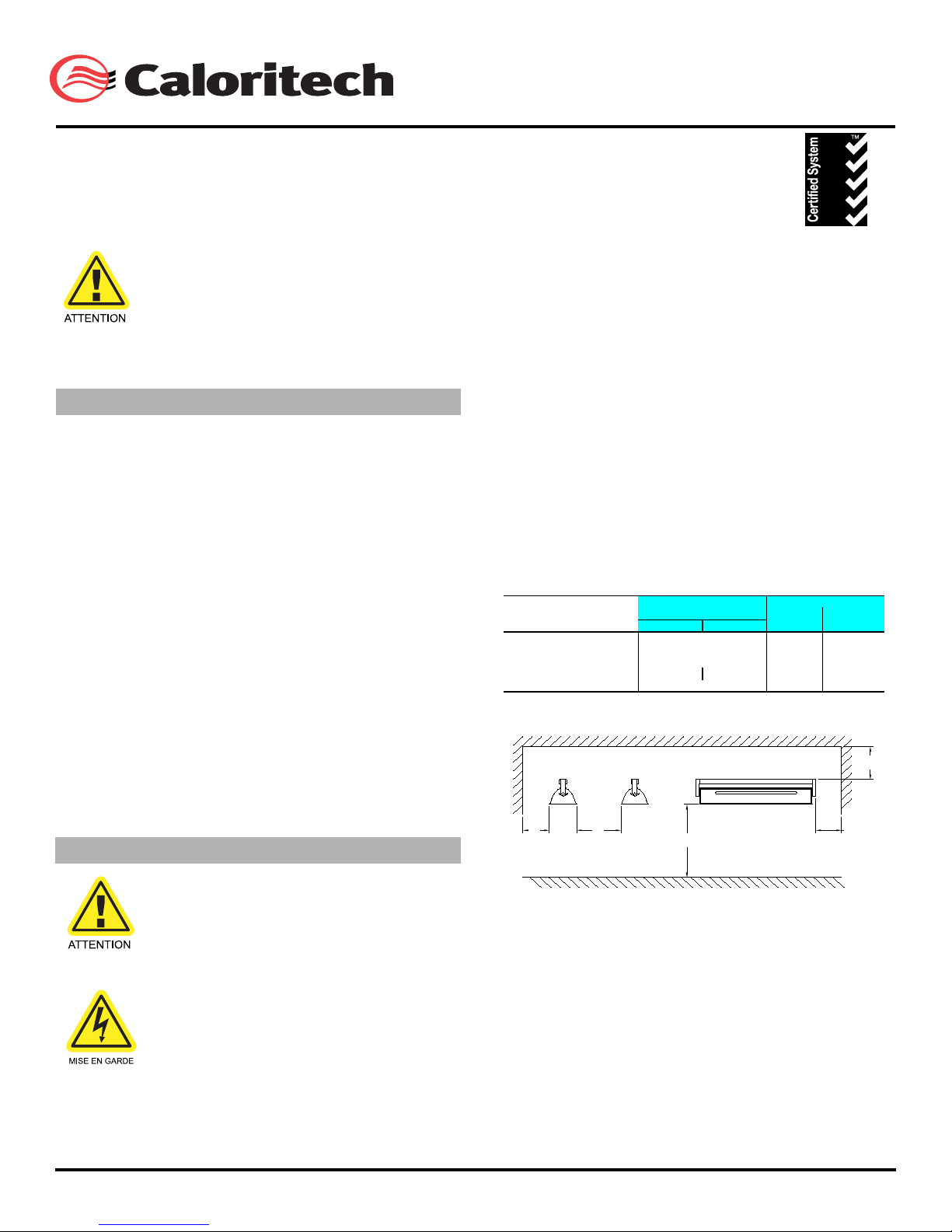
6.0When mounting, maintain a minimum clearance to
combustibles of 15”(381 mm) at sides, 10”(254 mm) at top and
12”(305 mm) at ends.
Heaters with quartz tube or quartz lamp
type heating elements are suitable for
horizontal mounting only. Heaters with
metal sheathed heating elements can
be mounted in any desired position.
7.0For short circuit protection, heaters must be installed with
proper fast acting fuses or breakers as close as possible to the
amperagedraw of the unit(s), in compliancewiththe local electrical
codes.
380 mm
[15”]300 mm
[12”]
250 mm
[10”]
FIG. 1 –MOUNTING CLEARANCES
CCI Thermal Technologies Inc. 2721 Plymouth Drive, Oakville, ON L6H 5R5 Tel. (905) 829-4422 Fax (905) 829-4430
www.ccithermal.com
Pour les elements à gaines métalliques,
lacontamination de l’isolation ou
l’accumulationd’humidité peut causer un
problême à la gainede l’élément générant un arc
électrique etlaissant couler du metal en fusion.
Installer unsystème de fuite à la terre adéquat
pourprévenir des blessures et/ou des domages
auxbiens.
11.0 Les boîtiers de raccordement à chacune des extrémités ont
un volume de 56 po³(917 cm³) pour OKH et OKD et 12 in3(196cm3)
pour OKB.
12.0 Les ls de raccordement doivent pouvoir supporter une
température de 194°F(90°C). Un câble armé exible est fortement
recommandé pour les applications protégées des conditions
climatiques extérieures.
13.0 Pour protection de court-circuit, les unités de chauffage
doivent être protégés avec des fusibles à action rapide ou
disjoncteurs dont l’ampèrage inscrit sur la plaque signalitique en
conformité avec le code élecrique local.
Les radiateurs à tube de quartz ou lampe de quartz
doivent être montés horizontalement seulement.
Les radiateurs à tubes métalliques peuvent être
montés en toutes positions désirées.
14.0 Pour le raccordement (tous les appareils, à l’exception du
modèle de type R), retirer la canalisation supérieure an d’y
installer le raccord pour conduit et raccorder les ls d’alimentation
et de mise à la terre aux ls de raccord. Replacer la canalisation
jusqu’au prochain service. L’appareil de type R possède un boîtier
résistant à l’humidité qui recouvre les terminaux d’un élément
tubulaire formé en U. Utiliser un conduit rigide (½”) pour assurer
l’étanchéité.
En faisant les raccordements au radiateur, NE
TIREZ PAS les ls d’alimentation du couvercle.
Tirer les ls peut éliminer la boucle d’expansion
à la connection du bout de l’élément et peut
endommager l’isolation des ls.
15.0 Suivrela procédure ci-après,réf.Fig. 2,pourun tube oulampe
de quartz lors de l’installation:
15.1 Débrancher l’alimentation principale.
15.2 Retirer les couvercles des boîtiers de terminaison aux
deux extrémités de l’appareil.
15.3 Retirer la vis d’ancrage sur un des supports de retenue et
glisser le support de céramique de l’élément de côté.
15.4 Faire passer le l d’alimentation de l’élément dans le
trou du support de céramique à l’extrémité xe en premier
lieu. Glisserle support de céramique (retiré au par. 15.3) par
dessus l’élément,de telle sorte que l’élément est maintenant
contenu entre les deux supports de céramique et revisser la
vis d’ancrage.
15.5 Dévisser légèrement la vis du terminal électrique sur
le bloc de céramique pour exécuter le raccordement de
l’alimentation électrique.
15.6 Pour raccorder le l de l’élément, glisser les supports
de céramique aussi loin que possible vers le centre de la
xture et boucler le l de l’élément au terminal électrique en
laissant très peu de jeu dans le l. (Veuillez noter que les
supports de céramique sont conçus pour glisser librement lors
de l’expansion thermiquede l’élément et les ls de raccord
‘tendus’ permettent de retenir l’élément en position).
15.7Raccorder les ls d’alimentation aux terminaux électriques
etremetter en placeles couverclesdesboîtiers determinaison.
15.8 Avant de mettre sous tension, essuyer la gaine de quartz
et le réecteur à l’aide d’un linge imprégné d’alcool.
Pour les éléments à gaines métalliques, vous
devez en premier lieu effectuer une lecture dela
résistance. Les éléments n’atteignant pas 1MΩ
doivent passer par une procédure desèchage.
Veuillez s’il-vous-plait consulter lefabricant pour
les détails sur la procédure àsuivre si l’élément a
moins de 1MΩ.
16.0 Serrer la vis de réglage dans la pièce coulée d’extrémité (une
extrémité seulement) après avoir installé le radiateur et avoir réglé
l’angle d’inclinaison horizontale. Cette vis doit être serrée même si
le radiateur n’est pas incliné.
17.0 Mettre l’appareil sous tension à la tension indiquée sur la
plaque signalétique et vérier visuellement si l’élément glisse
librement dans ses supports lorsqu’il prend de l’expansion.
(Un léger échissement au centre de l’élément est normal tout
spécialement sur les appareils de longueurs importantes).
18.0 Les radiateurs, avec éléments tubulaires métalliques, qui
n’ont pas été en opération pour une période prolongée, doivent
être remis en opération sous surveillance pour les premières
trente minutes.
OPÉRATION