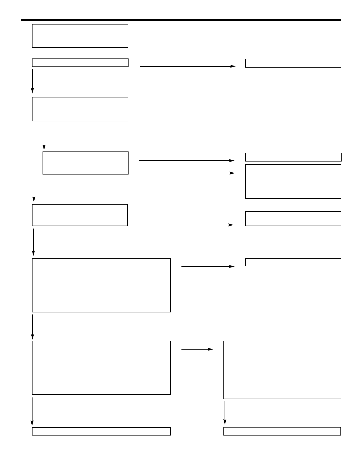
Troubleshooting: common problems and solutions
Cause
-Switch in ‘off’ position
-Machine not plugged in
-GFCI tripped
-Overload on motor tripped
-Circuit breaker tripped
-Water supply not turned on
-Plugged nozzle on wand
-Trigger gun off or malfunctioning
-Plugged spray nozzle
-Inlet screen is plugged
-Insufficient water supply
-Unloader valve stuck open
-Plugged inlet or discharge hose
-Use of additional lengths of hose
-Partially plugged spray nozzle
-Worn nozzle
-Soap (low pressure tip installed)
-Restricted or leaking water hose
-Cavitation (inadequate water supply)
-Worn pump packings
-Fouled inlet or discharge valves
-Broken valve spring
-Worn or restricted unloader valve
-Restricted discharge
-Valve on gun/wand not open
-Injector valve not turned on
-Discharge hose too long
-Clogged injector pick-up hose
-Clogged injector
-Worn plungers or packings
-All valves fouled
-Unloader valve seat fouled
-Leak in trigger or discharge
-High humidity or direct water spray
-Worn seals
Malfunction
PPrreessssuurreewwaasshheerrwwiillllnnoottrruunn
UUnniittrruunnssbbuuttnnoowwaatteerrddiiss-
cchhaarrggeess
LLoowwnnoozzzzlleepprreessssuurree
SSuurrggiinnggpprreessssuurreeoorrddrrooppiinn
pprreessssuurree
PPrreessssuurreeaattppuummppbbuuttlloowwddiiss-
cchhaarrggeepprreessssuurreeaattgguunn
CChheemmiiccaalliinnjjeeccttoorrnnoottwwoorrkkiinngg
pprrooppeerrllyy
WWaatteerrlleeaakkssffrroommppuummppmmaannii-
ffoolldd
UUnnllooaaddeerrddooeessnnoottbbyyppaassss
UUnnllooaaddeerrccyycclleesswwhheenngguunniiss
sshhuuttooffff
WWaatteerriinnccrraannkkccaassee
Remedy
-Turn switch to ‘on’ position
-Plug machine into adequate service
-Reset GFCI
-Allow automatic overload to cool or push the
reset button located on motor to reset
-Reset circuit breaker in main panel
-Turn on water supply
-Remove, clean, or replace nozzle
-Remove, repair, or replace trigger gun
-Remove nozzle and clean or replace
-Remove filter and clean or replace
-Secure adequate water supply
-Disassemble and clean; repair or replace
-Flush or replace hoses
-Reduce discharge hose length.
-Remove nozzle and clean or replace
-Remove and replace nozzle
-Remove and install one of the nozzles
-Check inlet hose and filter; clean or replace
-Secure adequate water supply
-Inspect and replace worn packings
-Inspect valves and clean or replace
-Inspect and replace valve spring
-Inspect unloader and repair or replace
-Check for discharge obstructions in injector,
hose, wand, and unloader
-Open valve by turning forward handle counter-
clockwise. (see wand breakdown page 10)
-Turn on injector by turning fitting on injector
-Reduce hose length or reposition injector to
within forty feet of trigger gun
-Remove and clean or replace
-Disassemble, clean, and reassemble
-Inspect and replace
-Inspect valves and clean or replace
-Inspect and clean or replace
-Inspect leaking fittings and repair or replace
-Reduce oil change intervals
-Replace seals
Despite the complexity of your power washing equipment, a number of common complaints stem from rela-
tively simple problems. With guidance, the user can identify and remedy many common problems.
Always disconnect the power supply before attempting to service any equipment.
6