manuals.online logo
Brands
  1. Home
  2. •
  3. Brands
  4. •
  5. Cambridge Air Solutions
  6. •
  7. Accessories
  8. •
  9. Cambridge Air Solutions E Series User manual

Cambridge Air Solutions E Series User manual

Popular Accessories manuals by other brands

Quincy lab 140AE-1 operating manual

Quincy lab

Quincy lab 140AE-1 operating manual

HomePro ZIR000 user manual

HomePro

HomePro ZIR000 user manual

DOL 20SCR Technical user guide

DOL

DOL 20SCR Technical user guide

RAB Smart Task installation manual

RAB

RAB Smart Task installation manual

Kemppi KMS 300 quick guide

Kemppi

Kemppi KMS 300 quick guide

Stearns 57,500 Series Installation and service instructions

Stearns

Stearns 57,500 Series Installation and service instructions

iGuzzini TWILIGHT COPENAGHEN manual

iGuzzini

iGuzzini TWILIGHT COPENAGHEN manual

Adelaide Annexe & Canvas Avan Deluxe installation guide

Adelaide Annexe & Canvas

Adelaide Annexe & Canvas Avan Deluxe installation guide

OHAUS 5000 instruction manual

OHAUS

OHAUS 5000 instruction manual

HOME8 WLS1300 quick start guide

HOME8

HOME8 WLS1300 quick start guide

MAXBOTIX MaxSonar quick start guide

MAXBOTIX

MAXBOTIX MaxSonar quick start guide

ioSmart iSmart56 Installation and user guide

ioSmart

ioSmart iSmart56 Installation and user guide

Focusrite Scarlett 18i8 user guide

Focusrite

Focusrite Scarlett 18i8 user guide

Velleman ED38105 user manual

Velleman

Velleman ED38105 user manual

JumpSport SkyBounce user manual

JumpSport

JumpSport SkyBounce user manual

Prima-Temp PRIYA Instructions for use

Prima-Temp

Prima-Temp PRIYA Instructions for use

Tefcold BC85I-BC85I W user manual

Tefcold

Tefcold BC85I-BC85I W user manual

Vaisala WMS302 user guide

Vaisala

Vaisala WMS302 user guide

manuals.online logo
manuals.online logoBrands
  • About & Mission
  • Contact us
  • Privacy Policy
  • Terms and Conditions

Copyright 2025 Manuals.Online. All Rights Reserved.

E-TM1-0220
E-SERIES
Evaporative Cooling
TECHNICAL MANUAL
WARNING:
Improper installation, adjustment, alteration, service or maintenance can
cause property damage, injury or death. Read the installation, operating, and
maintenance instructions thoroughly before installing or servicing this equipment.
Made in the USA
LIMITED WARRANTY
Cambridge Air Solutions Limited Warranty is included with the Terms and Conditions that are sent with
every Order Acknowledgement. For questions regarding the Limited Warranty, contact Cambridge Air
Solutions Customer Service Group at 1-800-473-4569 during the hours of 8:00 a.m. to 5:00 p.m. Central
Time, Monday through Friday.
Copyright © 2020
Cambridge Air Solutions
All Rights Reserved
CONTENTS
SAFETY CONSIDERATIONS ..................................................................................................4
OVERVIEW OF MANUAL.......................................................................................................5
RECEIVING, OFFLOADING, AND RIGGING INSTRUCTIONS.........................................5
Receiving Checklist..............................................................................................................5
Resolving Shipping Damage ................................................................................................6
Forklifting Considerations ...................................................................................................6
Preparing the Unit Site .........................................................................................................6
Offloading and Rigging Instructions...................................................................................6
General Lifting Considerations............................................................................................7
Unit Placement and Assembly..............................................................................................7
SECTION TO SECTION ASSEMBLY ......................................................................................7
Assembly Hardware .............................................................................................................8
INSTALLATION ─ MECHANICAL ........................................................................................8
INTERNAL ASSEMBLY ..........................................................................................................8
EXTERNAL CONNECTIONS ..................................................................................................8
Duct Connections.................................................................................................................8
Fan Discharge Connections..................................................................................................8
FILL AND DRAIN VALVE SCHEMATIC ..............................................................................9
Condensate Drain Connections.......................................................................................... 10
Electrical Connections ....................................................................................................... 10
START-UP ................................................................................................................................ 10
Media Cooling Pads Operating Installation....................................................................... 11
Start-Up Checklist.............................................................................................................. 11
MAINTENANCE.....................................................................................................................12
TROUBLESHOOTING............................................................................................................ 14
SERVICES AVAILABLE ......................................................................................................... 14
ORDER NOTES ....................................................................................................................... 14
CAMBRIDGE ENGINEERING PARTS LIST (COMMON PARTS)..................................... 15
Cambridge Air Solutions
760 Long Road Crossing Dr.
Chesterfield, MO. 63005
Phone: (636) 532-2233, (800) 899-1989
Fax: (636) 530-6133
www.cambridgeair.com
E-SERIES
Evaporative Cooling
TECHNICAL MANUAL
NEED UPDATED
TABLE OF
CONTENTS
Cambridge Air Solutions. 4 E-Series Technical Manual
GENERAL INFORMATION:
Cambridge Air System’s E-Series Direct Evaporative
Coolers are custom fabricated air handlers.
They use evaporative cooling to meet specific usage and
dimensional requirements. Use this manual to install,
start-up, operate and maintain the E-Series models.
A careful review of this manual will help minimize
installation, start-up, and maintenance difficulties.
Operating Environment
The unit is designed for outdoor applications. When
considering the placement of the E-Series, it is important
to consider the operating environment. The acceptable
temperature range for unit operation is -10°F to 115°F.
CAUTION:
Do not subject the unit to temperatures above
140°F / 60°C..
NOTE: Careful consideration is also required if the
unit will be installed within a coastal temperate zone.
Additional protective coatings may be necessary to
prevent corrosion.
SAFETY CONSIDERATIONS:
Throughout this manual are Warnings, Cautions and
Notes to alert the installing contractors, service and
maintenance personnel of potential hazards that could
result in personal injury, death or serious damage to
property or equipment.
Your personal safety and the proper operation of this
machinery depend on the careful observance of all
Warnings, Cautions and Notes:
WARNING:
Indicates a potentially hazardous situation which, if
not avoided, could result in death or serious injury.
CAUTION:
Indicates a potentially hazardous situation which,
if not avoided, could result in minor or moderate
injury, or to alert against unsafe practices.
NOTE: Indicates a situation that could result in
equipment or property damage, or provides important
information on installation considerations.
WARNING:
Proper Field Wiring and Grounding Required!
All field wiring MUST be performed by qualified
personnel. Ensure all field wiring and grounding
is accomplished in full accordance with National
Electrical Code (NEC) and local/state electrical
codes. Failure to do so may pose FIRE or
ELECTROCUTION hazards resulting in death or
serious injury.
WARNING:
Personal Protective Equipment (PPE) Required!
Installing/servicing this unit could result in
exposure to electrical, mechanical and chemical
hazards.
• Before installing/servicing this unit, technicians
MUST wear all recommended Personal Protective
Equipment (PPE) for the specific work being
undertaken.
ALWAYS refer to appropriate Safety Data Sheets
(SDS) sheets and OSHA guidelines for proper
PPE.
• When working with or around hazardous
chemicals, ALWAYS review appropriate SDS
and OSHA guidelines to ensure compliance with
safety standards for personal exposure levels,
proper respiratory protection and handling
recommendations.
• If there is a risk of arc or flash, technicians MUST
put on all PPE in accordance with the National
Electrical Code (NEC) for arc flash protection,
PRIOR to servicing the unit.
• Failure to follow recommendations could result in
death or serious injury.
E-SERIES DIRECT EVAPORATIVE COOLING (DEC)
E-Series Technical Manual 5 Cambridge Air Solutions
RECEIVING:
Upon receipt, examine units carefully for in-transit
damage or missing components as detailed in packing
list. If damaged, report damage(s) to trucking company,
take pictures, and contact Cambridge Air Solutions.
After uncrating unit, verify that it is the proper size and
that all loose parts are included.
NOTE: Inspect the exterior and interior of the equipment
carefully for any damage that may have occurred during
shipment. Verify shipped loose parts are complete and
undamaged. Ensure there is no damage to protruding
exterior components such as door handles, disconnect
switch handle, etc. or to internal components such as
pumps, media, filters, louvers and drains.
INSTALLATION:
WARNING:
Do not remove unit from shipping skid until it
is at the installation location. Moving these units
when not properly secured to the skid can result in
personal injury or death and can seriously damage
the unit.
WARNING:
To prevent injury or death, and damage to unit,
ensure the lifting capacity of the moving equipment
exceeds the weight of the unit by an adequate
safety margin.
NOTE: Ensure all local building and electrical codes are
fully complied with in installing the unit.
Take the following factors into consideration before
selecting the location of installation:
• Ensure sufficient clearance, per the submittal, to
allow easy access for maintenance and system
operation.
• Unit must be installed on a level foundation
that allows for proper flow of condensation into
internal drains, sufficient to support continuous
to full perimeter of base and cross members, and
minimize deflection of unit base frame to no more
than 1/16th “ (1.6mm) over the length and width of
unit.
WARNING:
To prevent injury or death, disconnect electrical
power source before completing connection to
the unit. All wiring must comply with National
Electrical Code (NEC) and state and local
requirements. Outside the United States, the
national and or local electrical requirements of
other countries shall apply.
The installing contractor must connect appropriate
power wiring to the terminal block or non-fused,
unit-mounted disconnect in the power section of
the unit control panel.
WARNING:
During installation, testing, servicing, and
troubleshooting of this product, it may be necessary
to work with live electrical components. To
prevent injury or death due to electrocution, take
extreme care when performing service procedures
with electrical power energized. Have a qualified
licensed electrician or other individual who has
been properly trained in handling live electrical
components perform these tasks. Failure to
follow all safety precautions when exposed to
live electrical components could result in death or
serious injury.
1. All installation should be performed in accordance to
local and state codes and with proper permits.
2. Measure the unit for correct sizes compared to the
submittal. Immediately contact Cambridge Air
Solutions if the unit’s openings do not match.
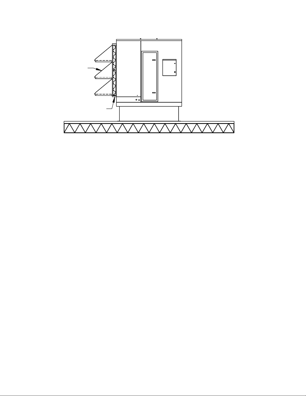
3. Check for proper air flow direction.
4. Set the unit in place. Make sure the unit covers the
entire air inlet opening.
5. Fasten the unit in place with the self-drilling screws
provided with the unit.
NOTE: Take care not to drill or screw into sump tank.
6. Check for air leakage. Air leakage will lower the
efficiency of the unit.
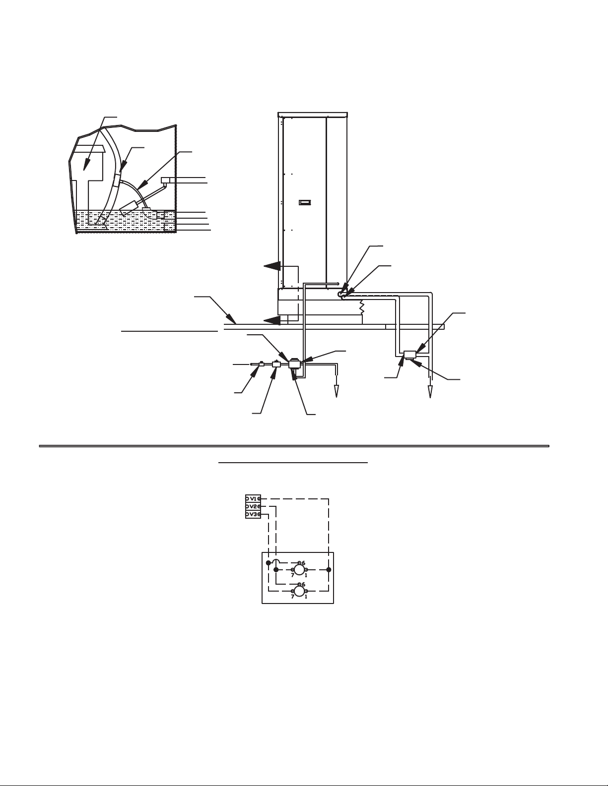
7. Check that the unit is level for proper water transfer
through the system.
8. Check that the sump pump has a good seal to the
floor.
Cambridge Air Solutions. 6 E-Series Technical Manual
Roof Top Configuration – E-Series
24" MOUNTING CURB
INLET DAMPER
RAINHOOD
W/ FILTERS
Fan Discharge Connections
To ensure the highest fan efficiency, duct turns and transitions must be made carefully, minimizing air friction losses
and turbulence. Proper ductwork installation, as outlined by such organizations as Sheet Metal and Air Conditioning
Contractors National Association, Inc. (SMACNA), should be followed closely.
PLUMBING / FILL AND DRAIN VALVES:
1. All installation should be performed in accordance to local and state codes and with proper permits.
2. The make-up water connection is ½” FPT.
3. Install a 3-way fill valve under the roof (in a conditioned space) to keep the pipe from freezing (see attached
schematic).
4. The 2-way drain valve can be installed outdoors or indoors under the roof line in a frost-free environment. See
schematic below. If the 2-way drain valve is installed outdoors (above the roof level), valve cover(s) are required.
Auto Drain with Freeze Protection (Optional)
Install a two-way drain valve on the sump’s drain connection. Install a three-way fill valve under the roof-line with
port “AB” piped to the make-up water connection from the sump. Port “A” is piped to the city water supply and port
“B” is piped to an approved roof drain. (See attached drawing.)
During normal operation of the unit the drain valve will be shut and the fill valve is open from port ”A” to port “AB”
letting city water enter the sump. Water level is adjusted and controlled by a float assembly to a level ½” inch below
the overflow. On a freeze signal or a signal from the 24-hour time clock, the drain valve will open allowing the sump
to drain. Simultaneously, the fill valve will shut off the city water, closing port ”A” to port “AB” but will open port
“AB” to port “B,” thus allowing the remaining water in the exposed pipe from the valve to the sump to drain to keep
the pipe from freezing. A low-water cut off switch will protect the pump(s) from running dry.
During installation, relocate the freeze stat bulb (located inside the electric control panel) to the outside of the
enclosure to ensure correct temperature readings.
E-Series Technical Manual 7 Cambridge Air Solutions
FILL VALVE SCHEMATIC:
NOTE: ALL PLUMBING, PIPING, AND FIXTURES EXTERNAL TO UNIT ARE TO BE
FURNISHED AND INSTALLED BY OTHERS UNLESS OTHERWISE INDICATED.
8
FILL VALVE SCHEMATIC :
NOTE: ALL PLUMBING, PIPING, AND FIXTURES EXTERNAL TO UNIT ARE TO BE FURNISHED AND
INSTALLED BY OTHERS UNLESS OTHERWISE INDICATED.
Cambridge Air Solutions. 8 E-Series Technical Manual
FILL AND DRAIN VALVE SCHEMATIC
Drain, Overflow and Make-Up Water Piping for Autodrain with Freeze Protection
NOTE: *Wiring may change ifpumps provided by others.
FILL & DRAIN KIT
24V CONTROL TB
FROM UNIT
(FIELD INSTALLED & WIRED)
FILL & DRAIN KIT WIRING SCHEMATIC
2 WAY VALVE*
3 WAY VALVE*
DRAIN OVERFLOW
1" DRAIN
WATER SUPPLY LINE
VIEW
Scale: None
A - A
Evap Pump
Bleed
Tube
Manifold
Supply
Tube
Service Valve
(by others)
Pressure Regulator
(by others) Three Way Drain
& Fill Valve
Water Supply (Refer to manual
pressure guide)
End B
End A
Roof Line
UNIT MUST BE LEVEL
A
A
Two Way Drain Valve
Normally Open
End A
End B
1" Drain
Drain Overflow
**All wiring must comply with local and national electrical codes.
NOTE: ForDual Inlet Units, separate connections
are required for each evaporative section.
E-Series Technical Manual 9 Cambridge Air Solutions
ELECTRIC PANEL / WIRING:
The pump and low level switches are wired to a J-Box in
the DEC module.
Wiring to the control panel is pre-wired and coiled up in
the Electrical Control Enclosure for termination in the
field.
Factory-supplied power and control wiring are to be
field-connected to the terminal strip located in the Jbox-
mounted on the DEC.
NOTE: Power is supplied and installed by others.
• All installations should be performed in accordance
to local and state codes and with proper permits.
• Wire the unit according to approved submittals and
the wiring diagram.
Cambridge Air Solutions. 10 E-Series Technical Manual
MEDIA COOLING PADS OPERATING INSTALLATION:
45
15
Do not expose CELdek®evaporative cooling pads to sparks, open flame, welding spatter, temperatures
in excess of 3500F, or other sources which may ignite the paper. GLASdek®will not readily ignite,
unless exposed to a direct flame or extremely high temperatures for an extended period of time.
Test Results for ASTM-E84 Standard Method of Test for Surface Burning Characteristics of Building Materials
PRODUCT Flame Spread Index Smoke Density
CELdek 450 420
GLASdek 0 20
Mi-T-Dark®,DRIFdek®, & COOLdek®15 745
IMPORTANT
Installation
In order to get the best performance from your Munters cooling pads, they must be installed properly. If you have
purchased a pad with two equal angles, they can be installed in either direction.
Depending on the application, pads are manufactured with special angle combinations. Those having combinations
of 150x 450or 300x 450are made to direct more water toward the
air entering side of the pads. If installed backwards, the pads may
not work properly.
Munters pads must always be installed with the steeper flute
angle sloping down toward the air entering side. The reasoning is
simple, the steeper angle puts more water on the entering side of
the pad where the air is hot, dry, and dusty and extra water it is
needed most. The unequal angles also counteract the tendency
of the air to push the water toward the air leaving side of the pad.
CELdek “New Pad” Odor
CELdek is made from materials similar to those used in paints,
carpets, paneling and wallpaper. CELdek pads must be flushed
with water to remove the new construction odors.
If you find the smell of the new paper to be objectionable, you
should run water over the pad for 2-5 hours without the fan
running. Change the water often, using bleed off or dump cycles.
If the odor continues after one or two days, call Munters
customer service. Please have full details of when and from
whom the pad was purchased.
Caution
The data and suggestions contained herein are based on information Munters believes to be reliable. They are offered in good faith but without guarantee, as conditions and methods of use are beyond our
control. We recommend that the prospective user determine the suitability of our media and suggestions before adopting them on a commercial scale.
For more information Contact Munters Corporation, HumiCool Division 239-936-1555
©Copyright Munters Corporation 2002 Printed in USA
Engineering Bulletin EB-OI-0906
MEDIA ORIENTATION
INSTRUCTIONS