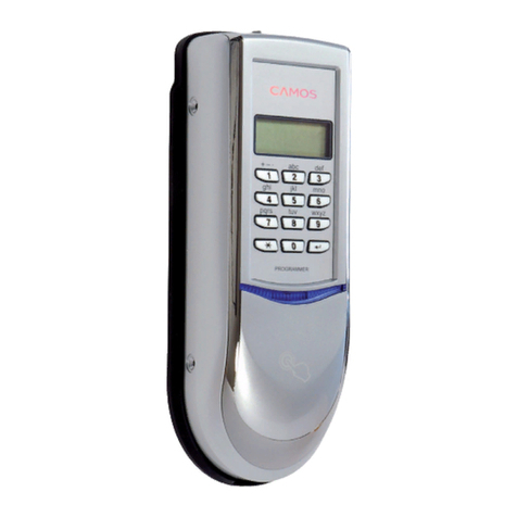
Camos EASY HOME User manual

123
456
789
*0
BIOMETRIC FINGERPRINT RECOGNITION
EASY HOME / EASY MOBILE
User Manual

2
SAFETY INSTRUCTIONS
Warning
Never open the units. You may risk
an electrical shock or to damage sen-
sitive parts.
In case of any defect, please power
off the system and consult your local
dealer or the manufacturer.
This system is designed for use with
9 - 27 V low power supplies only.
While installation and usage don’t
handle with violence. In most cases
malfunctions have a reason.
Please install the system according
to usual precautions. Be aware of
unprotected electrical power wires.
Please clean the system with soft
cloth. Don’t use oily, acid or soapy
liquids.
Please use the sensor with your fin-
gers only. Sharp objects or extreme
force may damage it.
In case the sensor is very wet, please
use a dry soft cloth to clean it. Water
cannot damage the sensor, but it can
decrease the reading capability.
Safety advise
Even if the system locks or unlocks
your house or car, you will be held
responsible for proper locking.
Leaving your house or car, please
make sure that it is properly locked.
Before selecting and installing an
electromechanical locking system,
please check your insurance police,
if and which means are covered.
Please be aware that children‘s fin-
gerprints may vary during their ado-
lescence. Normally you should re-
enrol every six months.
Just to be on the safe side, it is rec-
ommended to enrol at least two fin-
gers per person.
You have purchased a high quality hi-tech product.
Please handle with care and caution.

3
TABLE OF CONTENTS
Contents
Thank you for purchasing an
Easy Home / Easy Mobile System.
Produced by CAMOS Europe GmbH
Copyright © 2007 CAMOS Europe GmbH
Printed in Korea
All rights reserved
Subject to change without prior notice. All product names
might be brands or registered trademarks. All rights re-
served. Reprint, nor in extracts, is not permitted without
our express written approval.
2 SAFETY INSTRUCTIONS
4 BASICS
4 Technology
5 Applications
6 FIRST STEPS
6 Shipment
7 Key pad
8 Menu structure
9 Login
10 New PIN
11 Language
12 Enrol new
13 Fingerprint Sensor Usage
14 USER MENU
14 Verify ID
15 Delete ID
17 SETUP
17 Sleep timer
18 Alarm
19 Door sensor
20 Device ID
21 CONNECTORS
21 Out 1
22 Out 2
23 Out mode
24 Relay time
25 SYSTEMCHECK
25 Check door
26 Check all
27 FW-UPDATE
27 Controller
28 Set default
29 FW-INFO
29 Controller and Reader
30 TECHNICAL DATA
30 Specifications

4
BASICS
Technology
„Biometrics“ refers to all kind of methods for
uniquely recognition of humans based on
one or more specific physical or behavioural
characteristics. The more unique those char-
acteristics are, the more they are applicable
for definite identification.
The oldest of all biometric methods is the
finger print identification, the so-called
dactyloscopy (greek. dactylos „finger” and
scopein „view”).
1896 in Argentina the dactyloscopy was intro-
duced country wide for criminal investigations.
Nowadays these methods become more and
more accepted as access control method.
A biometric system uses three components,
the sensor, the trait extraction (enrolment)
and the comparison.
The sensor sends as result a fingerprint tem-
plate. This template is an extract that is ad-
justed for optimal results. After the enrolment
the template is digitally encrypted and stored.
It is not possible to re-construct a complete
image from the template.
While using the biometric system, the stored
template will be compared to the current one.
If the matching rate is within certain toleranc-
es, the template will be accepted as valid.
The most significant quality and reliability traits
of a biometric system are its failure rates: The
False Acceptance Rate (FAR) and the False
Rejection Rate (FRR).
More critical for consumer applications is the
FAR value. It is more dangerous when an un-
authorized person gets access than the rejec-
tion of authorized persons.
Besides a quick algorithm the sensor is the
most important part for the reliabilty, speed
and security of the biometric system.
The Easy Home / Easy Mobile is equipped
with a high performance sensor using the
latest available technology. It is a so-called
active capacitive hybrid sensor. This sensor
doesn’t take a “picture” of the finger surface, it
measures the conductivity of the saline layer
below the dry epidermis. Since the young skin
is “build” there, the skin ridge pattern is exact
the same than on the surface. Therefore this
sensor type is more applicable for children
with soft and people with dry and horny skin,
can also handle small injuries like scratches
or cuts.
Furthermore the sensor can recognize replica
fingers
In comparison to swipe sensors, at which the
finger must be drawn with the same speed
and accuracy at any time over the sensor,
the handling of a flatbed sensor is as easy as
pushing a simple button.
Because of all the above mentioned reasons,
the Easy Home / Easy Mobile system is suit-
able for all day usage for families and small
offices and contributes a high level conven-
ience.
About biometrics.

5
BASICS
Applications
Easy Home
Easy Home was developed for the use in the
automotive industry. The approval regulations
are much stronger than for domestic applica-
tions, particularly with regard to more inten-
sive environmental impacts, such as sunlight,
moisture or temperature fluctuations.
Since our products meet those requirements,
they are most suitable for domestic usage.
To use the Easy Home you need to install an
electromechanical door locking system. The
most popular method is an electric strike, the
most elaborate seems to be an integrated
motorized door lock. Both methods differ not
only in security level, but also in cost and in-
stallation effort.
Every average DIY might install an electric
strike. If necessary, consult an expert.
Various kinds of locking systems can be con-
nected to the Easy Home. In case that large
electrical loads must be switched, heavy duty
relays can be integrated in-between. For ex-
ample sliding doors, garage doors, shutters
etc.
Another application field is the controlling of
alarm systems with the Easy Home.
Easy Mobile
As explained above, the Easy Mobile meets
the requirements of mobile applications. The
system is well protected against environmen-
tal influences and it is designed to consume
only a minimum of battery ressources in
stand-by mode.
But, of course, the system is only applicable if
an electro-mechanical door locking system is
installed, too. In best case your car is already
equipped with a central door locking system.
Otherwise, please contact your local dealer to
check the possibilities for backfitting.
There are at least two ways to connect the
Easy Mobile:
By wire
Both relay contacts can handle loads up to
130 mA to switch circuits directly. In all other
cases you may need to interpose heavy duty
relays. In both cases you should try to find the
connecting points to your central locking.
By remote control
If you own a remote controlled locking, the
easiest way is to get a free remote sender.
With a little experience you can connect the
relay outputs of the Easy Mobile to the push
buttons of the sender module.
Both solutions require good knowledge about
your car’s locking system. If necessary, please
consult your dealer or a specialist.
How to use the CAMOS systems.

123
456
789
*0
6
FIRST STEPS
Shipment
1Outdoor reader with mounting bracket and
rubber fitting
2Controller with mounting bracket and
furniture protector
3Data cable reader-controller, 1 m
The components.
Controller
Main unit Mounting bracket
Fingerprint reader
Mounting bracket Reader
Installation material
4Pluggable screw terminals with 2,4 and 6
pins
5Two-core installation wire, 5 m
6Screws and small parts
7Not shown: manual, installation scheme
1
2
3
4
5
6

,
~
/
~
~
123
456
789
*0
7
All component settings are prepared to
work out of the box after installation. The
major tasks after the installation are to set the
master password and to enrol the fingerprints
of the authorized persons.
For more individual settings the control unit
is equipped with a display and a key pad. On
the following pages all expert functions will be
explained step by step.
Please make yourself familiar with the signs
and symbols on the right side.
How to use the key pad and how read the step by step guide.
The keys shown must be
pressed successively.
For entering numbers the
digits from 0 to 9 are valid.
Value range up to 99.
Valid values are 1 or 2 only.
Input is not necessary and
might be skipped.
Cancel the current job,
leave the system menu, de-
lete a character (text input).
Signs and symbols
Illustration Explanation
FIRST STEPS
Key pad
For input, numbers and let-
ters are acceptable. Please
use the key pad similar to
the T9 key oad of mobile
phones.

∂User Menu
∑Delete ID
∑Delete ID
∑Out mode
∑Out mode
∑Alarm
∑Alarm
∑Francais
∑Francais
∂Connectors
∂Connectors
∂Setup
∂Language
∂FW-Info
∂FW-Update
∂Systemcheck
∂Systemcheck
∑Enrol new
∑Output 1
∑Output 1
∑New PIN
∑New PIN
∑English
∑English
∑Controller
∑Controller
∑Verify ID
∑Verify ID
∑Output 2
∑Output 2
∑Sleep timer
∑Sleep timer
∑Deutsch
∑Deutsch
∑Reader
∑Reader
∑Set default
∑Set default
∑Check all
∑Check all
∑Controller
∑Controller
∑Check door
∑Check door
∑Delete all
∑Relay time
∑Relay time
∑Door contact
∑Door contact
∑Espanol
∑Espanol
∑Device ID
∑Device ID
2
46
8
*
8
FIRST STEPS
Menu structure
The menu structure and navigation.
The basic functions are available after single
login into the system menu.
Some expert settings require exact knowl-
edge about the functionality of the BIOLOCK
components. Access to these functions will
be granted by re-entering the PIN number.
Please read this manual carefully before
changing any settings!
Menu functions which are password protected
separately, are marked with .
Handling
To set up the system you need to navigate
through the below menu structure. For this
purpose you will use the keys , ,
and . For a better understanding,
please imagine a virtual 2D-button:

~ ,
You are logged in.
You are logged off.
,~,
C A M O S
C A M O S
PIN please
PIN please
∂User Menu
∂User Menu
∂User Menu
∂User Menu
9
Step by step guide
Display Input
The access to the main menu is protected by
a personal identification number (PIN).
The factory default PIN is „1234”. It is recom-
mended to change the PIN immediately after
first login.
On the following pages all functions will be ex-
plained. To achieve a higher legibility, the login
procedure will be shown in a short form:
After an adjustable time the system will auto-
matically log off. This minimizes the risk of an
unauthorized access to essential functions.
The factory value is 10 seconds.
It is recommended to log-off manually after
finishing your current job as described on the
right side.
FIRST STEPS
Login
Login and access to system stettings and functions.
Step by step guide
Display Input

, ~ ,
,
~ ,
~ ,
∂User Menu
∂User Menu
∂Setup
∂Setup
∑New PIN
∑New PIN
New PIN:
New PIN:
Completed
Completed
∑New PIN
∑New PIN
PIN please
PIN please
10
Step by step guide
Display Input
FIRST STEPS
New PIN
The default PIN is „1234”. It is highly
recommended to change the PIN to a per-
sonal value.
The PIN might consist of 4 up to 12 digits. The
longer the PIN is, the more secure it is. Opti-
mal protection is achieved with a minimum of
5 digits. Usually PINs should not show any
relation to your personality, such as birthday,
age, etc.
The main unit of the BIOLOCK system will be
installed inside. The risk of spying out your
PIN by a third party might be considered as
relatively low.
However, if you feel that you have been
observed while entering your PIN, please
change immediately.
For professional applications periodical
changing of the PIN is recommended.
How to change the PIN.

, ~ ,
,
∂User Menu
∂User Menu
∑Language
∑Language
Vorgang beendet
Vorgang beendet
∑Deutsch
∑Deutsch
∑Deutsch
∑Deutsch
11
Step by step guide
Display Input
The default language for the display and the
menu is English. With less effort you can se-
lect your favourite language.
Please follow the instructions on the right, re-
booting the system is not necessary.
FIRST STEPS
Language
How to select another language.

, ~ ,
~ ,
~ ,
∂User Menu
∂User Menu
∑Enrol new
∑Enrol new
Finger ID:XX
Finger ID:XX
Name:abc
Name:abc
Finger please...
Finger please...
Free:XX
Free:XX
∑Enrol new
∑Enrol new
12
Step by step guide
Display Input
Fingerprints will be stored as so-called “Tem-
plates” in the memory of the control unit. It is
not possible to re-construct complete finger-
print images from the templates, but to com-
pare two templates with each other.
The memory is organized like a relational da-
tabase, i.e. every fingerprint will be assigned
to a unique storage index (ID) number. Every
new fingerprint will be allocated to the next
available ID. The ID can also be assigned
manually during the enrolment.
It is recommended to keep a separate list of
the assigned ID numbers and reference it to
user names. This will enable you to delete or
overwrite individual templates very easily.
If you want to overwrite a used memory ID,
you must confirm the hint in the display by
pressing .
FIRST STEPS
Enrol new
Register new fingerprints.

1. 2. 3. 4.
13
FIRST STEPS
Fingerprint Sensor Usage
How to use the fingerprint reader.
Open sensor cover. Blue LED turns on. Place finger smoothly
and straight.
Close sensor cover.
max. 30°
As smoothly
as possible
Hints
For security reasons there is an inte-
grated time-out after 3 seconds.
For security reasons you will have
only three attempts for fingerprint
recognition. After that you have to
close and open the cover again.
If the sensor position is inconvenient
for using your forefinger, we recom-
mend to use your thumb.
Please find your way to place the fin-
ger with the biggest possible contact
area. Try to use the swilley for orien-
tation.

, ~ ,
,
~ ,
∂User Menu
∂User Menu
∑Verify ID
∑Verify ID
Finger please...
Finger please...
ID okay:XX
ID okay:XX
∑Verify ID
∑Verify ID
Finger ID:XX
Finger ID:XX
14
Step by step guide
Display Input
USER MENU
Verify ID
After enrolment you might want to verify the
fingerprint. Please enter the ID and let the
system check your finger again.
This function is helpful if the reader must be
installed in a difficult position and in case you
are not sure that placing the finger is conven-
ient for you for a longer time.
It will enable you to test several times without
activating the door opening mechanism.
Verify existing fingerprint templates.

, ~ ,
, ,
~ ,
∂User Menu
∂User Menu
∑Delete ID
∑Delete ID
Delete ID?
Delete ID?
Please wait...
Please wait...
Completed
Completed
Finger ID:XX
Finger ID:XX
∑Delete ID
∑Delete ID
15
Step by step guide
Display Input
A single fingerprint template can be deleted
by its storage number, its ID.
Vice versa you cannot delete a fingerprint
without its ID. If you want to use the system
with a high volatile user group, it is recom-
mended to keep a separate list with user to ID
reference. Otherwise the database must be
erased completely and the remaining persons
must be registered again.
Alternatively, you might assign the storage
IDs manually to differentiate user groups, i.e.
0-19 for family, 20-39 for guests, etc. This will
enable you to distinguish between permanent
persons and guests.
USER MENU
Delete ID
How to delete one fingerprint template.

, ~ ,
,
∂User Menu
∂User Menu
∑Delete all
∑Delete all
Please wait...
Please wait...
Completed
Completed
Delete all?
Delete all?
∑Delete all
∑Delete all
16
Step by step guide
Display Input
You can delete all stored templates in one
step.
Please use this functionality carefully, the re-
maining persons must be registered again!
How to delete all stored fingerprint templates.
USER MENU
Delete all

, ~ ,
,
~ ,
,
~ ,
∂User Menu
∂User Menu
∂Setup
∂Setup
∑Sleep timer
∑Sleep timer
After (5-99s):XX
After (5-99s):XX
∑Sleep timer
∑Sleep timer
PIN please
PIN please
17
Step by step guide
Display Input
You can log off the system menu whenever
your current task is completed by pressing
the key.
In case that you cannot finish your job or if
you get distracted, the system will log off after
a certain period for security reasons.
This period for the sleep mode timer can be
adjusted from 5 to 99 seconds.
How to set the sleep timer.
SETUP
Sleep timer

, ~ ,
,
~ ,
, ,
/ ,
~ ,
∂User Menu
∂User Menu
∂Setup
∂Setup
∑Alarm
∑Alarm
On1,Off2:X
On1,Off2:X
Mode (1-3):X
Mode (1-3):X
PIN please
PIN please
∑Alarm
∑Alarm
18
Step by step guide
Display Input
How to use the alarm function.
The control unit provides a sensor input that
operates as normally closed (NC) door switch.
This means, the quiescent current will be
interrupted in case of opening the door. For
example you can connect a dry reed con-
tact (NC). The system can react with various
activities.
The alarm function is deactivated by default
and can be activated as explained in the right
side.
1 Enables the alarm function
2 Disables the alarm function
After activating the alarm function, you may
select one of the three modes:
1 Upon alarm event, output 1 will be com-
mutated.
2 Upon alarm event, output 2 will be com-
mutated.
3 Upon alarm event, the controller will indi-
cate optically and acoustically only, with-
out changing the outputs.
The alarm can be disarmed by a valid PIN
number or positive fingerprint matching only.
Best usage for optical alarm signal. When you
return to your home or car, you can see from
the distance that something happened.
Please consider local regulations for acoustic
alarms. In most cases the maximum duration
is limited to 1 minute.
SETUP
Alarm

, ~ ,
,
~ ,
, ,
/ ,
∂User Menu
∂User Menu
∂Setup
∂Setup
∑Door contact
∑Door contact
On1,Off2:X
On1,Off2:X
∑Door contact
∑Door contact
PIN please
PIN please
19
Step by step guide
Display Input
The controller is equipped with a sensor input
that is prepared for a NC (normally closed)
door contact, i.e. a dry reed contact.
The system can detect that the door is open,
and react accordingly.
Please check the installation guide for proper
installation.
The door contact is disabled by default. You
may enable as explained herein.
1 Enables the door contact
2 Disables the door contact
When enabled and the door is open, the out-
puts will remain active until the door will be
closed again. The relay time will be ignored.
Example: If you use a magnetic door lock, the
magnet is inactive until the door is closed.
This will save power and extend lifetime of
the coil inside the lock.
How to activate the door sensor.
SETUP
Door sensor

, ~ ,
,
~ ,
,
~ ,
∂User Menu
∂User Menu
∂Setup
∂Setup
∑System ID
∑System ID
Sensor ID:X
Sensor ID:X
∑Device ID
∑Device ID
PIN please
PIN please
BMR-207: Reader
8421
8421
20
Step by step guide
Display Input
How to set the system ID.
Due to security reasons reader and control-
ler must be paired. In case of exchanging the
reader, the system will not work.
The units are paired by factory settings. Un-
der normal conditions it is not necessary to
change the ID. Anyhow, if you like to change
the system ID, you may select a system ID
from 1 to 15.
You need to change the ID via DIP switch on
the back side of the reader and the settings in
the system menu.
An overview of the valid DIP switch settings
and its meaning you may find in the installa-
tion guide.
SETUP
Device ID
This manual suits for next models
1
Table of contents
Other Camos Door Lock manuals