Campa ConvectAir Manual

EXCEPTIONALLY RADIANT
INSTALLATION &
OPERATING INSTRUCTIONS
(READ CAREFULLY BEFORE ANY OPERATION - DOCUMENT TO BE KEPT BY END USER)
IMPRESARIO – LIVING SPACES
MODEL NUMBER : 7716
421AA2558-2 109339/12

Page 2
Dear owner,
- Congratulations on the purchase of this premium electric heater. CONVECTAIR
develops and produces the highest quality heating products in the electrical
industry.
- To obtain the best results and the ultimate in performance and comfort,
please take a moment to read the installation, operation and maintenance
instructions detailed in this manual.
1. - QUICKSTART GUIDE page 3
2. - SPECIFICATIONS page 4
3. - RECOMMENDED SET-UP page 4
4. - INSTALLATION AND MOUNTING page 6
5. - ELECTRICAL CONNECTION page 7
6. - OPERATING INSTRUCTIONS page 8
7. - MAINTENANCE AND ADVICE page 15
8. - TROUBLESHOOTING page 16
9. - IDENTIFICATION OF YOUR HEATER page 17
WARRANTY AND REGISTRATION Back Cover
TABLE OF CONTENTS
INTRODUCTION

Page 3
QUICKSTART GUIDE
1
Electrical requirements : 208 V / 220-240 V
Install a 2 in. x 3 in. wall junction box, positioned within the space defined by the
wall bracket. Lowest fixing hole of wall bracket should be at 32 cm (12 1/2”) from
the floor (page 6 Fig. B).
Installing and connecting the heater : (pages 4-7).
To turn the heater ON : Press the ON/Standby key (page 8).
To set the temperature : Turn the Temperature adjustment knob to raise or to
lower the temperature setting (page 8).
To change from °C to °F : (page 9)
To change Mode : Press the Mode key (Comfort > Economy > Frost protection
> Program > Comfort >... (pages 9-10).
To lock or unlock the control panel : Press and hold the Window key and the
Temperature adjustment knob at the same time (page 11).
Troubleshooting : (page 16).
To contact CONVECTAIR : (Back Cover).
“ON” indicator light “Open Window” Activate/Deactivate key Temperature adjustment knob
Heating indicator light
Operating mode displayOperating mode selection key
“ON/Stanby” key

Page 4
SPECIFICATIONS
RECOMMENDED SET-UP
2
3
Optional setback system (sold separately) :
Your IMPRESARIO can be fitted with the optional CONVECTAIR Programmer Modules
to program temperature setbacks in periods of prolonged absence, providing the
same comfort and more savings. For more information, contact your electrical
contractor or dealer, or call CONVECTAIR (see Back Cover).
PLEASE NOTE : Your heater must be installed in accordance with national and local codes and
CONVECTAIR recommends an installation by a qualified electrician.
CAUTION DO NOT COVER THE FRONT PANEL OR TOP OF THE HEATER
• Do not position the heater below an electrical receptacle.
• Your heater must be installed so that the control panel is out of reach from anyone in the
bath-tub or in the shower. Do not install over a bath-tub or spa.
• Do not install the heater behind a door, furniture or other obstacles, or in front of an air
exhaust vent.
• Keep combustible materials such as curtains, away from the heater.
• Your heater is equipped with a heating element that may reach high temperatures. Do not
install or operate in the presence of gasoline, paint solvents or other flammable products.
• Maintain the minimum required clearances (height from floor, distances from side walls or
furniture, drapes, etc).
Model
number
Description Capacity Voltage Current
draw
7716-C10 Impresario,
Radiant electric heater.800W / 1000W 208 / 220-240V,
60Hz 4A / 5A
7716-C15 Impresario,
Radiant electric heater. 1250W / 1500W 208 / 220-240V,
60Hz 6A / 7A
7716-C20 Impresario,
Radiant electric heater. 1600W / 2000W 208 / 220-240V,
60Hz 7A / 8A

Page 5
RECOMMENDED SET-UP (continued)
Fig. A:
Minimum clearances:
INSTALLATION HEIGHT :
20 cm (8 in.).
MINIMUM CLEARANCE IN
FRONT OF HEATER :
75 cm (30 in.).
3
Heater outline
Wall
Shelf or curtains
Surround
(30”)
Référence Puissance Courant Poids ABCDE
17 Kg 820 mm 565 mm 384 mm 294 mm 115 mm
7716-C10
7716-C15
7716-C20
800 / 1000W
1250 / 1500W
1600 / 2000W
4A / 5A
37.4 lbs
32 1/4 po. 22 1/4 po.
22.6 Kg 1098 mm 565 mm 662 mm 294 mm 115 mm
6A / 7A 49.7 lbs
61.6 lbs
43 1/4 po.
22 1/4 po.
26 po.
28 Kg 1098 mm 690 mm 662 mm 419 mm 115 mm
8A / 9A
43 1/4 po. 27 1/8 po.
26 po.
Niveau du sol
Pour l’introduction du module ou de l’interface de
programmation (option), il est conseillé de laisser
une distance de 300 mm entre l’angle du mur et
l’appareil suivant la position du fourreau récepteur.
200mm
(8”)
250mm
(10”)
C
D
E
11 1/2 po.
11 1/2 po.
16 1/2 po.
150mm (6”)
*300mm (12”)
*for Programmer
150mm
(6”)
F
Contour de l’appareil
Mur
Tablette et voilage
Meuble de face
(30”)
200mm
(8”)
250mm
(10”)
C
D
E
150mm (6”)
*300mm (12”)
*pour Programmeur
150mm
(6”)
F
4 1/2 po.
4 1/2 po.
32 cm (12 1/2”)
F
181 mm
181 mm
181 mm
7 1/8 po.
7 1/8 po.
7 1/8 po.
4 1/2 po.
15 1/8 po.
Floor level
When inserting the programming module or interface
(optional), we recommend leaving a 300 mm(12 in.) gap
between the corner of the wall and the heater to take the
receiver cover.
Reference Capacity Current Weight ABCDE
7716-C10
7716-C15
7716-C20
800 / 1000W
1250 / 1500W
1600 / 2000W
4A / 5A
6A / 7A
8A / 9A
F
Center Label
32 cm (12 1/2”)
Étiquette de centrage
de l’appareil
17 Kg 820 mm 565 mm 384 mm 294 mm 115 mm
37.4 lbs 32 1/4 in. 22 1/4 in.
22.6 Kg 1098 mm 565 mm 662 mm 294 mm 115 mm
49.7 lbs
61.6 lbs
43 1/4 in. 22 1/4 in.
26 in.
28 Kg 1098 mm 690 mm 662 mm 419 mm 115 mm
43 1/4 in. 27 1/8 in. 26 in.
11 1/2 in.
11 1/2 in.
16 1/2 in.
4 1/2 in.
4 1/2 in.
181 mm
181 mm
181 mm
7 1/8 in.
7 1/8 in.
7 1/8 in.
4 1/2 in.
15 1/8 in.

Page 6
INSTALLATION AND MOUNTING
4
- Remove the mounting bracket from the heater – loosen the locking screw if necessary.
- Respect all minimum clearances (page 5 Fig. A).
- Position the bracket on the wall, making sure it is properly oriented and that the bottom
fastening holes are at a height of 32 cm (12 1/2 in.) from the floor.
- On some models, the bracket may not be centered on the heater. Use the center refe-
rence mark on the bracket to position it.
- Check that the bracket is leveled and mark the 6 fixing holes.
- Install the appropriate wall anchors and fasten the mounting bracket with 6 screws.
Maximum screw size : 5,5mm (7/32 in.).
Heater outline
Wall
Shelf or curtains
Surround
(30”)
Référence Puissance Courant Poids ABCDE
17 Kg 820 mm 565 mm 384 mm 294 mm 115 mm
7716-C10
7716-C15
7716-C20
800 / 1000W
1250 / 1500W
1600 / 2000W
4A / 5A
37.4 lbs
32 1/4 po. 22 1/4 po.
22.6 Kg 1098 mm 565 mm 662 mm 294 mm 115 mm
6A / 7A 49.7 lbs
61.6 lbs
43 1/4 po.
22 1/4 po.
26 po.
28 Kg 1098 mm 690 mm 662 mm 419 mm 115 mm
8A / 9A
43 1/4 po. 27 1/8 po.
26 po.
Niveau du sol
Pour l’introduction du module ou de l’interface de
programmation (option), il est conseillé de laisser
une distance de 300 mm entre l’angle du mur et
l’appareil suivant la position du fourreau récepteur.
200mm
(8”)
250mm
(10”)
C
D
E
11 1/2 po.
11 1/2 po.
16 1/2 po.
150mm (6”)
*300mm (12”)
*for Programmer
150mm
(6”)
F
Contour de l’appareil
Mur
Tablette et voilage
Meuble de face
(30”)
200mm
(8”)
250mm
(10”)
C
D
E
150mm (6”)
*300mm (12”)
*pour Programmeur
150mm
(6”)
F
4 1/2 po.
4 1/2 po.
32 cm (12 1/2”)
F
181 mm
181 mm
181 mm
7 1/8 po.
7 1/8 po.
7 1/8 po.
4 1/2 po.
15 1/8 po.
Floor level
When inserting the programming module or interface
(optional), we recommend leaving a 300 mm(12 in.) gap
between the corner of the wall and the heater to take the
receiver cover.
Reference Capacity Current Weight ABCDE
7716-C10
7716-C15
7716-C20
800 / 1000W
1250 / 1500W
1600 / 2000W
4A / 5A
6A / 7A
8A / 9A
F
Center Label
32 cm (12 1/2”)
Étiquette de centrage
de l’appareil
17 Kg 820 mm 565 mm 384 mm 294 mm 115 mm
37.4 lbs 32 1/4 in. 22 1/4 in.
22.6 Kg 1098 mm 565 mm 662 mm 294 mm 115 mm
49.7 lbs
61.6 lbs
43 1/4 in. 22 1/4 in.
26 in.
28 Kg 1098 mm 690 mm 662 mm 419 mm 115 mm
43 1/4 in. 27 1/8 in. 26 in.
11 1/2 in.
11 1/2 in.
16 1/2 in.
4 1/2 in.
4 1/2 in.
181 mm
181 mm
181 mm
7 1/8 in.
7 1/8 in.
7 1/8 in.
4 1/2 in.
15 1/8 in.
F
ig
. B
CAUTION
Because of the heavy weight of this heater, particular care must be taken when handling and installing it. Use
screws and anchors adapted to the wall type and weight of the heater.

Page 7
ELECTRICAL CONNECTION
5
CONVECTAIR recommends that the heater be installed by a qualified electrician and in
accordance with national and local codes.
A standard rectangular junction box must be installed in the wall, prior to electrical hookup.
The box must be of appropriate size to receive the necessary electrical connections and the
7 cm x 11,5 cm (2 3/4 in. x 4 in.) cover that is supplied with the heater.
CAUTION This heater must be connected to a 208V or 220-240 Volt (60 cycles) circuit.
1- Connect the ground wire (C) to the green conductor (G) from the heater (see Fig. C).
2- Connect the two line wires to the red (R) and black (B) conductors from the heater.
3- The purple conductor with a plastic seal (PW) is only to be used when connecting the hea-
ter to a central CONVECTAIR Programmer (for more informations, contact CONVECTAIR by
calling1 800 463-6487 or online at www.convectair.com).
4- Carefully place all conductors in the wall junction box.
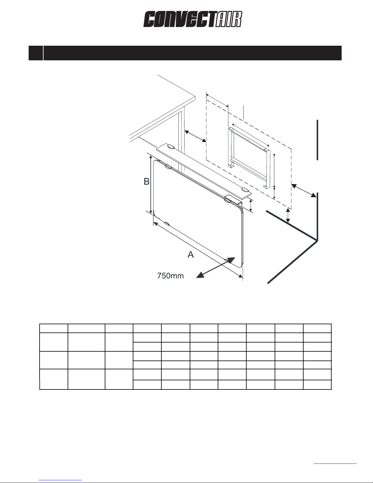
5- Position the heater in front of the bracket, angling it so that the top is away from the wall.
6- Lift the heater slightly to hook the bottom of the heater on the bracket.
7- Attach the two safety chains.
8- Lift and push the heater towards the wall to place it on the bracket. Lock it into position
with the plastic locking screw.
CAUTION
To prevent short circuits and electrical shocks, turn the power off at the main panel before installing or repairing
the heater. If the power cord of the appliance is damaged, it must be replaced by CONVECTAIR or an approved
service depot to avoid any danger.
Fig. C: Connection diagram - Respect wire coding
HEATER
RR
RR
RR
WW
BB
BB
BB
BB
GG
GG
CC
CC
P=PURPLE R=RED B=BLACK G=GREEN C=COPPER W=WHITE PW=PILOT WIRE
P W P W
WITH the use of a pilot wire (PW)
Installation
in Canada
Installation
in Canada
Installation
in U.S.A
Installation
in U.S.A
WITHOUT the use of a pilot wire (PW)
POWER LINE
HEATER
HEATER
HEATER
POWER LINE
POWER LINE
POWER LINE
P
PPP

Page 8
OPERATING INSTRUCTIONS
6
“ON” indicator light “Open Window” Activate/Deactivate key Temperature adjustment knob
Heating indicator light
Operating mode display
Operating mode selection key
“ON/Stanby” key
Throughout the heating season, your CONVECTAIR heater stays warm and maintains a constant tempe-
rature in the room.
During cold spells, it is normal for the heater to become hotter. Young children should be
cautioned about this and be supervised when they are in the heater vicinity.
THERMOSTAT OVERVIEW
Your Impresario heater is equipped with an advanced electronic thermostat featuring two
display modes plus a setting mode.
1 - DISPLAY LEVEL 0 : BASIC MODE USING FACTORY DEFAULT ADJUSTMENTS (Pages 9 – 11)
All the basic functions are immediately accessible.
2 - DISPLAY LEVEL 1 : ADVANCED MODE (Pages 11-12)
This display mode gives access to finer temperature adjustments and displays additional
information.
3 - DISPLAY LEVEL 2 : SETTINGS (Page 12-13)
Thermostats settings can be adjusted to allow or disallow access to some functions, as well
as change the temperature display (°C or °F) and the screen backlight.
Changing the temperature scale from Celsius to Fahrenheit
1 - Press the ON/Standby key to turn the heater off (blank screen)
2 - Simultaneously press the ON/Standby and Mode keys and hold for 3 seconds.
The screen displays : NIV 0 or NIV 1.
3 - Press the Window key for 3 seconds.
The screen displays : NIV 2
4 - Press the Mode key 5 times (until the screen displays º C or º F).
5 - Turn the Temperature adjustment knob to change from º C or º F and back.
6 - Press the Mode key twice or wait until the screen returns to its normal display.
DISPLAY LEVEL 0 : BASIC MODE USING FACTORY DEFAULT ADJUSTEMNTS
To turn the heater ON:
Press the ON/Standby key to turn the heater ON. The green indicator
light and the display screen show the heater is operational. Press again to
put the heater in Standby mode.
To change the desired temperature:
Turn the temperature adjustment knob up or down. The red heat indicator
light shows when the heating element is activated.
To select the operating mode:
Press the Mode key to switch from Comfort to Economy, Frost protection
and Automatic mode.
Comfort Mode Eco Mode Frost protection Mode Auto Mode
The thermostat maintains
the temperature
displayed on the sceen.
Night setback setting:
3.5 º C (6 º F) below the
Comfort temperature.
Maintains a minimum
temperature of 7 º C
(40 º F) for long tern
absences.
The heater will respond
to the instructions
coming from an optional
Programmer module.
1
OPERATING INSTRUCTIONS (continued)

Page 9
6OPERATING INSTRUCTIONS (continued)
6
Changing the temperature scale from Celsius to Fahrenheit
1 - Press the ON/Standby key to turn the heater off (blank screen)
2 - Simultaneously press the ON/Standby and Mode keys and hold for 3 seconds.
The screen displays : NIV 0 or NIV 1.
3 - Press the Window key for 3 seconds.
The screen displays : NIV 2
4 - Press the Mode key 5 times (until the screen displays º C or º F).
5 - Turn the Temperature adjustment knob to change from º C or º F and back.
6 - Press the Mode key twice or wait until the screen returns to its normal display.
DISPLAY LEVEL 0 : BASIC MODE USING FACTORY DEFAULT ADJUSTEMNTS
To turn the heater ON:
Press the ON/Standby key to turn the heater ON. The green indicator
light and the display screen show the heater is operational. Press again to
put the heater in Standby mode.
To change the desired temperature:
Turn the temperature adjustment knob up or down. The red heat indicator
light shows when the heating element is activated.
To select the operating mode:
Press the Mode key to switch from Comfort to Economy, Frost protection
and Automatic mode.
Comfort Mode Eco Mode Frost protection Mode Auto Mode
The thermostat maintains
the temperature
displayed on the sceen.
Night setback setting:
3.5 º C (6 º F) below the
Comfort temperature.
Maintains a minimum
temperature of 7 º C
(40 º F) for long tern
absences.
The heater will respond
to the instructions
coming from an optional
Programmer module.
1
OPERATING INSTRUCTIONS (continued)

Page 10
6OPERATING INSTRUCTIONS (continued)
6
The Auto Mode : using the heater with an optional Programmer or other Pilot wire system.
PROGRAMMER
INSTRUCTION DESCRIPTION SCREEN DISPLAY
Comfort temperature set on
the heater, ex : 19.5 °C (67 °F)
3.5 °C (6 °F) setback from the
comfort temperature
The thermostat sets itself to frost
protection mode : 7 °C (40 °F)
The heater stops heating
Comfort mode
Economy or setback mode
(“Eco”)
Frost Protection mode
(“HG”)
Standby mode
(“- -”)
“Open window” function
This function allows the thermostat to respond to an abnormal temperature drop
(0.2 °C per minute for 7 minutes) that may be provoked by an open door or window.
If the function is activated, the heater would automatically go on Standby (no heat)
to avoid wasting energy.
To activate the Open Window detection, press the Window key . The window
icon appears on the screen. Press the same key to desactivate it.
If the thermostat detects an abnormal temperature drop, the heater goes in Standby
mode (no heat). The window icon on the screen and the green indicator light
both start to flash to indicate that the heater stopped.
To restart the heater, simply press on the Window key .
OPERATING INSTRUCTIONS (continued)

Page 11
OPERATING INSTRUCTIONS (continued)
Display Level 1 offers all the basic function of Level 0 plus the following features :
-The 4 mode icons are always displayed, with a triangle pointing to the current mode.
-When the thermostat activates the heating elements, the screen shows which heating
elements are active (front panel only or total power).
-The Economy temperature is displayed when the Comfort temperature is adjusted.
Current operating level
While your appliance is in standby mode, press the keys for approximately
3 seconds.
The following display will appear
on your screen
As soon as the screen displays , rotate the Temperature adjustment knob
to select level 1.
Confirm your selection by pressing the key.
SELECTING THE OPERATING MODE
Press the key to select your operating mode.
COMFORT MODE
When the system is in COMFORT MODE, the
mode indicator will be over the symbol.
When setting the COMFORT mode temperature,
the ECO mode temperature will appear in the top
right hand corner of the screen.
ECO MODE*
When the system is in ECO MODE, the mode
indicator will be over the symbol.
When setting the ECO mode temperature, the
COMFORT mode temperature will appear in the
top right hand corner of the screen.
FROST PROTECTION MODE
When the system is in FROST PROTECTION, the
mode indicator will be over the symbol.
Your appliance will maintain a minimum
temperature of 7°C +/- 3°C.
* In Eco mode, the economy temperature can be adjusted. When the ECO temperature is
adjusted, the screen also displays the current COMFORT setting. The ECO temperature can
be set anywhere between 7 °C (12.6 °F) and 3.5 °C (6.3 °F) below the COMFORT temperature.
This upper limit can be changed, see Display Level 2 below.
DISPLAY LEVEL 1 : ADVANCED OPTIONS
2
Control Panel Lock
To lock the panel : simultaneously press the Window key and
the Temperature adjustment knob until the symbol
appears on the screen. Use the same procedure to unlock the panel.
This function disables all the keys and the Temperature adjustment knob in order to prevent
unwanted tampering of the controls.
6
The Auto Mode : using the heater with an optional Programmer or other Pilot wire system.
PROGRAMMER
INSTRUCTION DESCRIPTION SCREEN DISPLAY
Comfort temperature set on
the heater, ex : 19.5 °C (67 °F)
3.5 °C (6 °F) setback from the
comfort temperature
The thermostat sets itself to frost
protection mode : 7 °C (40 °F)
The heater stops heating
Comfort mode
Economy or setback mode
(“Eco”)
Frost Protection mode
(“HG”)
Standby mode
(“- -”)
“Open window” function
This function allows the thermostat to respond to an abnormal temperature drop
(0.2 °C per minute for 7 minutes) that may be provoked by an open door or window.
If the function is activated, the heater would automatically go on Standby (no heat)
to avoid wasting energy.
To activate the Open Window detection, press the Window key . The window
icon appears on the screen. Press the same key to desactivate it.
If the thermostat detects an abnormal temperature drop, the heater goes in Standby
mode (no heat). The window icon on the screen and the green indicator light
both start to flash to indicate that the heater stopped.
To restart the heater, simply press on the Window key .
OPERATING INSTRUCTIONS (continued)

Page 12
Current operating level
While your appliance is in standby mode, press the keys for approximately
3 seconds.
The following display will appear
on your screen
As soon as the screen displays , rotate the Temperature adjustment knob
to select level 1.
Confirm your selection by pressing the key.
SELECTING THE OPERATING MODE
Press the key to select your operating mode.
COMFORT MODE
When the system is in COMFORT MODE, the
mode indicator will be over the symbol.
When setting the COMFORT mode temperature,
the ECO mode temperature will appear in the top
right hand corner of the screen.
ECO MODE*
When the system is in ECO MODE, the mode
indicator will be over the symbol.
When setting the ECO mode temperature, the
COMFORT mode temperature will appear in the
top right hand corner of the screen.
FROST PROTECTION MODE
When the system is in FROST PROTECTION, the
mode indicator will be over the symbol.
Your appliance will maintain a minimum
temperature of 7°C +/- 3°C.
* In Eco mode, the economy temperature can be adjusted. When the ECO temperature is
adjusted, the screen also displays the current COMFORT setting. The ECO temperature can
be set anywhere between 7 °C (12.6 °F) and 3.5 °C (6.3 °F) below the COMFORT temperature.
This upper limit can be changed, see Display Level 2 below.
DISPLAY LEVEL 1 : ADVANCED OPTIONS
2
OPERATING INSTRUCTIONS (continued)
Settings screen Meaning
Turn the temperature adjustment
knob to lock ot unlock functions
Locks or unlocks the
“open window” function
Function unlocked
Function unlocked
Permanent
15 seconds
Celsius
Fahrenheit
From 0.5°C to 9°C
in 0.1 increments.
This setting allows you to lock or unlock certain options and to adjust certain parameters.
FUNCTION LOCKING AND UNLOCKING
Switch off and then press the keys for 3 seconds.
Return to user mode
N.B. If you do not press any key, after a few seconds the system will automatically revert to level 0 or 1.
FUNCTION NOT AVAILABLE
Once the screen has shown or , press the key for 3 seconds.
The first setting screen will appear.
To move from one setting to another, press the key.
When the cycle has been completed, the screen reverts to the user mode with the
selected functions.
Function locked
Function locked
3
FUNCTION NOT AVAILABLE
Limited temperature
adjustment range : when
activated, this function only
allows the temperature
setting to be adjusted
within ± 2 °C
Screen backlight either
permanently or for 15
seconds after the latest
operation
Temperature displayed
in Celsius
or Fahrenheit
For setting the minimum
difference between
COMFORT temperature
and ECO temperature
DISPLAY LEVEL 2 : Locking and unlocking and associated functions
3
6

Page 13
OPERATING INSTRUCTIONS (continued)
Settings screen Meaning
Turn the temperature adjustment
knob to lock ot unlock functions
Locks or unlocks the
“open window” function
Function unlocked
Function unlocked
Permanent
15 seconds
Celsius
Fahrenheit
From 0.5°C to 9°C
in 0.1 increments.
This setting allows you to lock or unlock certain options and to adjust certain parameters.
FUNCTION LOCKING AND UNLOCKING
Switch off and then press the keys for 3 seconds.
Return to user mode
N.B. If you do not press any key, after a few seconds the system will automatically revert to level 0 or 1.
FUNCTION NOT AVAILABLE
Once the screen has shown or , press the key for 3 seconds.
The first setting screen will appear.
To move from one setting to another, press the key.
When the cycle has been completed, the screen reverts to the user mode with the
selected functions.
Function locked
Function locked
3
FUNCTION NOT AVAILABLE
Limited temperature
adjustment range : when
activated, this function only
allows the temperature
setting to be adjusted
within ± 2 °C
Screen backlight either
permanently or for 15
seconds after the latest
operation
Temperature displayed
in Celsius
or Fahrenheit
For setting the minimum
difference between
COMFORT temperature
and ECO temperature
DISPLAY LEVEL 2 : Locking and unlocking and associated functions
3
6

Page 14
RE-ALIGNING SETTINGS (thermostat/thermometer)
RE-INITIALIZING THE THERMOSTAT
Factory settings can be reinstated by simultaneously pressing
the 3 keys and the Temperature adjustment
knob for 10 seconds while the thermostat is in standby
mode.
(This operation can only be carried out while the heater is in standby mode)
Exceptionally, under certain conditions, there may be a difference between the figure
displayed by your screen and that provided by the thermometer. Should this occur, you
can re-align both settings.
This adjustment is only possible when your appliance is set to between 17 and 22°C.
All doors and windows must be closed.
Let the room temperature stabilize (at least 6 hours) and avoid coming into and going out of
the room as much as possible.
The control thermometer must be placed in the centre of the room at a height of 1.20 metres.
Do not place it on furniture.
After 6 hours, record the difference between the temperature shown by your thermometer and
that displayed by the appliance.
Simultaneously press both keys and the knurled setting button
for 10 seconds.
Turn the knurled setting button to reset the temperature as indicated by your thermometer.
Correction up to +/- 2°C
E.g. 20.5° on the thermometer, 19.5° on the
thermostat screen. Use the knurled setting button
to correct the setting by increasing it by +1° (20.5-19.5).
13
Press 2 times on the key
to validate your choice.
This symbol appears when you attempt unauthorised actions.
E.g.
Pressing a key when the “childproof lock” has been activated.
The set point temperature cannot exceed 19.5°C.
The ECO temperature cannot exceed 18°C.
Meaning of the symbol:
OPERATING INSTRUCTIONS (continued)
6

Page 15
MAINTENANCE AND ADVICE
7
To keep your CONVECTAIR unit clean, regular maintenance is suggested. To remove dust, use
a soft cloth. To remove a stain, use a damp cloth.
NEVER USE ABRASIVE OR ACETONE-BASED PRODUCTS TO CLEAN YOUR HEATER AS
THIS MAY DETERIORATE THE EPOXY FINISH.
ANY REPAIR ON YOUR CONVECTAIR HEATER SHOULD ONLY BE DONE BY A QUALIFIED TECHNICIAN, AND ONLY AFTER THE
HEATER HAS BEEN DISCONNECTED.
Operation and maintenance tips
Your CONVECTAIR heater will become hot when in use. Caution is advised when
young children are present.
Do not insert small objects in the heater, this could cause an electrical short circuit, fire
or damage to the inner components.
Any use or modifications not approved by CONVECTAIR may cause electrical short
circuits, fire or injuries to the users.
In certain cases, it is possible for yellowing of the surface to occur over time. This is not
due to a manufacturing defect. This is caused by surrounding air, which may contain
smoke or dust, being heated and circulated through the heater.
Prevention : it is suggested that surfaces be frequently cleaned especially with units
installed in locations where cigarette smoke is present or in the kitchen.
Never use this heater during construction work or other activities that gene-
rate a lot of dust.
Note : The first time your CONVECTAIR heater is used, a light smoke could be re-
leased. This is normal and should disappear after about 2 to 3 minutes.
RE-ALIGNING SETTINGS (thermostat/thermometer)
RE-INITIALIZING THE THERMOSTAT
Factory settings can be reinstated by simultaneously pressing
the 3 keys and the Temperature adjustment
knob for 10 seconds while the thermostat is in standby
mode.
(This operation can only be carried out while the heater is in standby mode)
Exceptionally, under certain conditions, there may be a difference between the figure
displayed by your screen and that provided by the thermometer. Should this occur, you
can re-align both settings.
This adjustment is only possible when your appliance is set to between 17 and 22°C.
All doors and windows must be closed.
Let the room temperature stabilize (at least 6 hours) and avoid coming into and going out of
the room as much as possible.
The control thermometer must be placed in the centre of the room at a height of 1.20 metres.
Do not place it on furniture.
After 6 hours, record the difference between the temperature shown by your thermometer and
that displayed by the appliance.
Simultaneously press both keys and the knurled setting button
for 10 seconds.
Turn the knurled setting button to reset the temperature as indicated by your thermometer.
Correction up to +/- 2°C
E.g. 20.5° on the thermometer, 19.5° on the
thermostat screen. Use the knurled setting button
to correct the setting by increasing it by +1° (20.5-19.5).
13
Press 2 times on the key
to validate your choice.

Page 16
TROUBLESHOOTING
8
PROBLEM CHECK ACTION
The heater
does not heat
Check that the display screen
and green light are ON. Press the ON/Standby key to ON.
The screen is ON, but the
heating indicator light is OFF.
Set the thermostat.
If the room temperature is
already high enough, the
heater will not heat.
The heater has been set to ECO
or Frost Protection mode by a
Programmer system : set the
Programmer to COMFORT.
The heating indicator light is still
OFF.
Check the home circuit
breakers.
Check that the heater is not
covered or blocked, causing the
overheat control to trip – if so,
allow the heater to cool down
and check its operation again.
The «Open Window» icon and
the green light are flashing.
The heater as detected an
«Open Window» condition and
stopped heating. Check doors
and windows and press the
Open Window key .
The heater
heats
continuously
Check that the thermostat
is not set too high.
Is the heater affected by
a cold draft (open door
or window, outside air
infiltration).
Set the thermostat.
Eliminate the cold draft.
The heater
does not
respond
to the
Programmer
Check that the
Programmer operates
properly.
Refer to the Programmer
instruction manual.
Press the Mode key to set
the thermostat in Auto mode.
Remove the Programmer or the
Receiver unit from its receptacle
and put it back in place.
The heater
is ON but
still does not
respond to
commands
The symbol appears on the
screen when a key is touched.
The control panel is in locked mode.
Simultaneously press on the Window
key and the Temperature
adjustment knob , and hold for 3
seconds to unlock the control panel.
IN ALL OTHER CASES, CONTACT YOUR ELECTRICIAN OR THE CLOSEST AUTHORIZED CONVECTAIR SERVICE CENTER
OR CALL THE CONVECTAIR HELP LINE AT 1 800 463-6478.

Page 17
IMPORTANT Product information appears on the heater’s identification label.
The identification label is located on the lower right hand side of the heater (same side as the
thermostat).
It includes :
- The complete model number and its production reference number (A) that must be included
in any warranty claim.
- Its capacity in Watts (B).
- The standard certification (C).
IDENTIFICATION OF YOUR HEATER
9
A
C
B

2 years against all defects/ 5 years on heating element.
All CONVECTAIR heaters are subject to a double warranty: 2 years on all parts and
manufacturing defects and 5 years on the heating element itself.
Warranty is applicable from date of purchase by the customer and under certain specific
conditions. All details are provided with each heater. Keep your invoices (purchase and/
or installation).
SERVICE CENTER :
Contact CONVECTAIR to find your closest Service center.
Toll-free : 1 800 463-6478
Register your CONVECTAIR heater
All CONVECTAIR heaters come with a warranty registration card to be filled and
returned by mail.
Register your CONVECTAIR heater to have easy access to customer service and support.
It is possible to register online, the online warranty registration of your product is fast
and simple, go to: www.convectair.com/warranty
WARRANTY
30, carré Sicard, Sainte-Thérèse, Qc, CANADA J7E 3X6
Tel. : (450) 433-5701 Fax : (450) 434-3166
E-mail : support@convectair.com
www.convectair.com
This manual suits for next models
1
Table of contents
Popular Electric Heater manuals by other brands

GHP Group
GHP Group Dyna-Glo X Series Installation & maintenance instructions

Dyna-Glo
Dyna-Glo EG7500DH User's manual and operating instructions

Trotec
Trotec IRD 1200 operating manual

Holmes
Holmes HRH848 owner's guide

EQUATION
EQUATION KJ350G-S1 Assembly, Use, Maintenance Manual

Nibe
Nibe DRAZICE OKC 200 NTR/HR 120 OPERATING AND INSTALLATION Manual