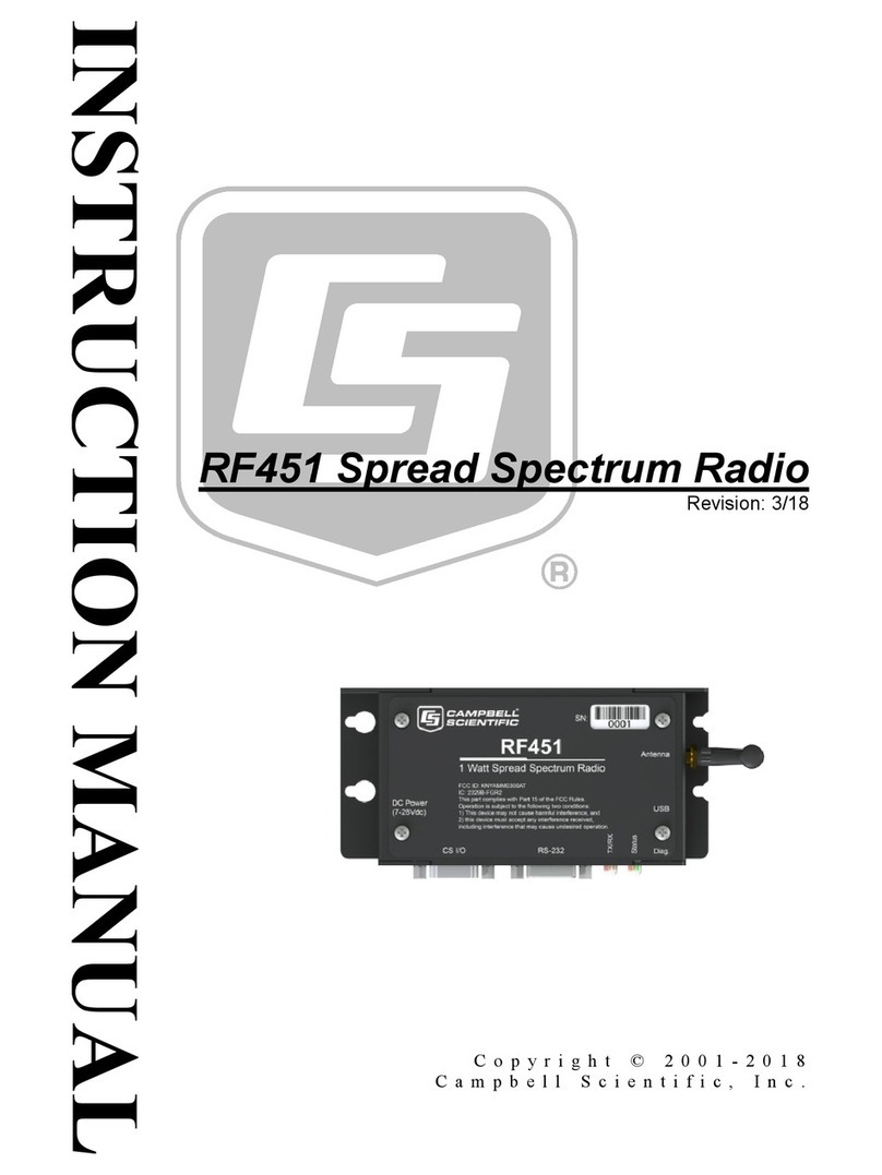
Campbell RF451 User manual

Revision: 11/2022
Copyright © 2001– 2022
Campbell Scientific
CSL I.D - 1203

Guarantee
This equipment is guaranteed against defects in materials and workmanship.
We will repair or replace products which prove to be defective during the
guarantee period as detailed on your invoice, provided they are returned to us
prepaid. The guarantee will not apply to:
Equipment which has been modified or altered in any way without the
written permission of Campbell Scientific
Batteries
Any product which has been subjected to misuse, neglect, acts of God or
damage in transit.
Campbell Scientific will return guaranteed equipment by surface carrier
prepaid. Campbell Scientific will not reimburse the claimant for costs incurred
in removing and/or reinstalling equipment. This guarantee and the Company’s
obligation thereunder is in lieu of all other guarantees, expressed or implied,
including those of suitability and fitness for a particular purpose. Campbell
Scientific is not liable for consequential damage.
Please inform us before returning equipment and obtain a Repair Reference
Number whether the repair is under guarantee or not. Please state the faults as
clearly as possible, and if the product is out of the guarantee period it should
be accompanied by a purchase order. Quotations for repairs can be given on
request. It is the policy of Campbell Scientific to protect the health of its
employees and provide a safe working environment, in support of this policy a
“Declaration of Hazardous Material and Decontamination” form will be
issued for completion.
When returning equipment, the Repair Reference Number must be clearly
marked on the outside of the package. Complete the “Declaration of
Hazardous Material and Decontamination” form and ensure a completed copy
is returned with your goods. Please note your Repair may not be processed if
you do not include a copy of this form and Campbell Scientific Ltd reserves
the right to return goods at the customers’ expense.
Note that goods sent air freight are subject to Customs clearance fees which
Campbell Scientific will charge to customers. In many cases, these charges are
greater than the cost of the repair.
Campbell Scientific Ltd,
80 Hathern Road,
Shepshed, Loughborough, LE12 9GX, UK
Tel: +44 (0) 1509 601141
Fax: +44 (0) 1509 270924
Email: support@campbellsci.co.uk
www.campbellsci.co.uk

About this manual
Please note that this manual was originally produced by Campbell Scientific Inc. primarily for the North
American market. Some spellings, weights and measures may reflect this origin.
Some useful conversion factors:
Area: 1 in2(square inch) = 645 mm2
Length: 1 in. (inch) = 25.4 mm
1 ft (foot) = 304.8 mm
1 yard = 0.914 m
1 mile = 1.609 km
Mass: 1 oz. (ounce) = 28.35 g
1 lb (pound weight) = 0.454 kg
Pressure: 1 psi (lb/in2) = 68.95 mb
Volume: 1 UK pint = 568.3 ml
1 UK gallon = 4.546 litres
1 US gallon = 3.785 litres
In addition, while most of the information in the manual is correct for all countries, certain information
is specific to the North American market and so may not be applicable to European users.
Differences include the U.S standard external power supply details where some information (for
example the AC transformer input voltage) will not be applicable for British/European use. Please note,
however, that when a power supply adapter is ordered it will be suitable for use in your country.
Reference to some radio transmitters, digital cell phones and aerials may also not be applicable
according to your locality.
Some brackets, shields and enclosure options, including wiring, are not sold as standard items in the
European market; in some cases alternatives are offered. Details of the alternatives will be covered in
separate manuals.
Part numbers prefixed with a “#” symbol are special order parts for use with non-EU variants or for
special installations. Please quote the full part number with the # when ordering.
Recycling information
At the end of this product’s life it should not be put in commercial or domestic refuse but
sent for recycling. Any batteries contained within the product or used during the
products life should be removed from the product and also be sent to an appropriate
recycling facility.
Campbell Scientific Ltd can advise on the recycling of the equipment and in some cases
arrange collection and the correct disposal of it, although charges may apply for some
items or territories.
For further advice or support, please contact Campbell Scientific Ltd, or your local agent.
Campbell Scientific Ltd, 80 Hathern Road, Shepshed, Loughborough, LE12 9GX,
UK Tel: +44 (0) 1509 601141 Fax: +44 (0) 1509 270924
Email: support@campbellsci.co.uk
www.campbellsci.co.uk

Safety
DANGER —MANY HAZARDS ARE ASSOCIATED WITH INSTALLING, USING, MAINTAINING, AND WORKING ON
OR AROUND TRIPODS, TOWERS, AND ANY ATTACHMENTS TO TRIPODS AND TOWERS SUCH AS SENSORS,
CROSSARMS, ENCLOSURES, ANTENNAS, ETC. FAILURE TO PROPERLY AND COMPLETELY ASSEMBLE,
INSTALL, OPERATE, USE, AND MAINTAIN TRIPODS, TOWERS, AND ATTACHMENTS, AND FAILURE TO HEED
WARNINGS, INCREASES THE RISK OF DEATH, ACCIDENT, SERIOUS INJURY, PROPERTY DAMAGE, AND
PRODUCT FAILURE. TAKE ALL REASONABLE PRECAUTIONS TO AVOID THESE HAZARDS. CHECK WITH YOUR
ORGANIZATION'S SAFETY COORDINATOR (OR POLICY) FOR PROCEDURES AND REQUIRED PROTECTIVE
EQUIPMENT PRIOR TO PERFORMING ANY WORK.
Use tripods, towers, and attachments to tripods and towers only for purposes for which they are designed. Do not
exceed design limits. Be familiar and comply with all instructions provided in product manuals. Manuals are
available at www.campbellsci.eu or by telephoning +44(0) 1509 828 888 (UK). You are responsible for conformance
with governing codes and regulations, including safety regulations, and the integrity and location of structures or land
to which towers, tripods, and any attachments are attached. Installation sites should be evaluated and approved by a
qualified engineer. If questions or concerns arise regarding installation, use, or maintenance of tripods, towers,
attachments, or electrical connections, consult with a licensed and qualified engineer or electrician.
General
•Prior to performing site or installation work, obtain required approvals and permits. Comply with all
governing structure-height regulations, such as those of the FAA in the USA.
•Use only qualified personnel for installation, use, and maintenance of tripods and towers, and any
attachments to tripods and towers. The use of licensed and qualified contractors is highly recommended.
•Read all applicable instructions carefully and understand procedures thoroughly before beginning work.
•Wear a hardhat and eye protection, and take other appropriate safety precautions while working on or
around tripods and towers.
•Do not climb tripods or towers at any time, and prohibit climbing by other persons. Take reasonable
precautions to secure tripod and tower sites from trespassers.
•Use only manufacturer recommended parts, materials, and tools.
Utility and Electrical
•You can be killed or sustain serious bodily injury if the tripod, tower, or attachments you are installing,
constructing, using, or maintaining, or a tool, stake, or anchor, come in contact with overhead or
underground utility lines.
•Maintain a distance of at least one-and-one-half times structure height, or 20 feet, or the distance
required by applicable law, whichever is greater, between overhead utility lines and the structure (tripod,
tower, attachments, or tools).
•Prior to performing site or installation work, inform all utility companies and have all underground utilities
marked.
•Comply with all electrical codes. Electrical equipment and related grounding devices should be installed
by a licensed and qualified electrician.
Elevated Work and Weather
•Exercise extreme caution when performing elevated work.
•Use appropriate equipment and safety practices.
•During installation and maintenance, keep tower and tripod sites clear of un-trained or non-essential
personnel. Take precautions to prevent elevated tools and objects from dropping.
•Do not perform any work in inclement weather, including wind, rain, snow, lightning, etc.
Maintenance
•Periodically (at least yearly) check for wear and damage, including corrosion, stress cracks, frayed cables,
loose cable clamps, cable tightness, etc. and take necessary corrective actions.
•Periodically (at least yearly) check electrical ground connections.
WHILE EVERY ATTEMPT IS MADE TO EMBODY THE HIGHEST DEGREE OF SAFETY IN ALL CAMPBELL
SCIENTIFIC PRODUCTS, THE CUSTOMER ASSUMES ALL RISK FROM ANY INJURY RESULTING FROM IMPROPER
INSTALLATION, USE, OR MAINTENANCE OF TRIPODS, TOWERS, OR ATTACHMENTS TO TRIPODS AND TOWERS
SUCH AS SENSORS, CROSSARMS, ENCLOSURES, ANTENNAS, ETC.

Table of contents
1. Introduction 1
1.1 Configuration options 1
2. Precautions 2
3. Initial inspection 3
4. QuickStart 3
5. Overview 4
6. Specifications 5
7. Configuring the RF451/RF452 7
7.1 Deployment settings 10
7.1.1 Active Interface 10
7.1.2 SDC Address 11
7.1.3 Baud Rate 11
7.1.4 Radio Operation Mode 11
7.1.5 Network ID 12
7.1.6 Frequency Key 12
7.1.7 Repeater Frequency Key 12
7.1.8 Transmit Power 13
7.1.9 Low Power Mode 14
7.1.10 Subnet ID 15
7.1.11 Radio ID 16
Table of Contents - i

8. Gateway radio 16
9. Endpoint 17
10. Repeater 18
11. LoggerNet setup 19
12. PakBus Graph 20
13. Transceiver location 21
14. Power considerations 21
15. RF451/RF452 antennas 22
16. Electrostatic issues 23
17. Troubleshooting 23
17.1 LED status 23
17.2 Troubleshooting scenarios 25
Appendix A. FCC notifications 26
Appendix B. Installation examples 27
B.1 RF451/RF452 radio communications with one or more data loggers 27
B.1.1 Configuring the RF451/RF452 radio connected to the computer 28
B.1.2 Configuring endpoint RF451/RF452 data loggers 29
B.1.3 Setting up communications between the RF451/RF452 data logger and the
computer 29
B.2 RF451/RF452 communications with multiple data loggers using one repeater 30
B.2.1 Configuring the RF451/RF452 radio connected to the computer 32
B.2.2 Configuring the data logger acting as a repeater 33
B.2.3 Adding the endpoint/repeater data logger to the LoggerNet network 34
B.2.4 Adding endpoint data loggers to the network 34
B.2.5 Using additional communications methods 34
B.3 Computer-to-RF network with parallel repeaters (using SubNetID) 35
B.4 Data logger call-back 38
Appendix C. Settings Editor 40
Table of Contents - ii

1. Introduction
The RF451/RF452 Spread Spectrum Radio is a 900MHz license-free radio specifically designed to
work with Campbell Scientific data loggers and existing RF450/RF451/RF452 networks. RF452
radios consist of a FreeWave® MM3 LV-T radio module and an interface board. RF451s and
RF450s contain the MM2 LV-T and DGR09 radio models, respectively.
This manual addresses the RF451/RF452 interface with CR6, CR1000X, CR800-series, CR350-
series, CR300-series, CR3000, and CR1000 data loggers and a computer running LoggerNet.
Additionally the CR6 data logger has an integrated RF451/RF452 option.
Though the radios may be set up in a point-to-point mode, this manual will only address multi-
point applications, as this is the only way to take advantage of the low-power mode of the
endpoint radios at the data logger site. This reduces the required power at remote sites from
about 75mA to less than 10mA in most applications.
NOTE:
This manual replaces the terms Master with Gateway and Slave with Endpoint.
1.1 Configuration options
The following images show the most frequently used configurations with the RF-series data
logger and RF-series radio:
RF451/RF452 Spread Spectrum Radio 1

2. Precautions
lIMPORTANT — Radios must be configured to use the proper hop table version to comply
with local laws and to avoid interference with other RF installations such as cellular services.
Available hop table versions are listed in the Device Configuration Utility Settings Editor for
the RF451/RF452. Hop table versions include North America (default), Australia, New
Zealand, Taiwan, Brazil, International, and Notch (custom). See Settings Editor (p. 40) for
more information.
lREAD AND UNDERSTAND the Safety section at the front of this manual.
lThis equipment generates, uses, and can radiate radio frequency energy and, if not
installed and used in accordance with the instructions, may cause harmful interference to
radio communications. See FCC notifications (p. 26) for more information.
lLine-of-sight obstructions and RF interference will affect the transmission distance. See
Line of Sight Technical Paper and Link Budget Technical Paper for a discussion of
antenna gain and other factors affecting distance.
RF451/RF452 Spread Spectrum Radio 2

3. Initial inspection
lUpon receipt of the RF451/RF452, inspect the packaging and contents for damage. File
damage claims with the shipping company. Contact Campbell Scientific to facilitate repair
or replacement.
lImmediately check package contents against shipping documentation. Thoroughly check
all packaging material for product that may be trapped inside it. Contact Campbell
Scientific immediately about any discrepancies. Model numbers are found on each
product. On cables, the model number is often found at the connection end of the cable.
4. QuickStart
1. Using Device Configuration Utility set a unique PakBus® Address for each data logger in
the network. Keep the other settings at their default. See Configuring the RF451/RF452 (p.
7)
2. Decide on a unique Network ID between 0 and 4095, excluding 255. All radios in the
network will use the same Network ID.
3. Select a Frequency Key between 0 and 14. It is recommended that you change this from the
default value of 5. Generally, all radios in the network will have the same Frequency Key.
4. Select one radio to be the gateway; the others will be designated as endpoints. The radio
designated as a gateway is able to simultaneously communicate with numerous endpoints.
5. Endpoint radios: Using Device Configuration Utility, set the Radio Operation Mode to
Endpoint. Set the Network ID to the number decided upon in step 2. Set the Frequency Key
to the number decided upon in step 3. Set the Radio ID to the PakBus Address assigned in
step 1. Keep the remaining settings at their defaults.
TIP:
The Radio ID setting allows a transceiver to be designated an arbitrary, user-selectable,
4-digit number which identifies the transceiver in diagnostics mode. When used in
conjunction with PakBus data loggers, we recommend this setting be assigned the
PakBus address of the station. This is because the Radio ID appears in the Network
Diagnostics application within the FreeWave Tool Suite software, and it allows the user
to associate a particular data logger with its attached radio.
RF451/RF452 Spread Spectrum Radio 3

NOTE:
If RF450/RF451/RF452 repeaters will be used, select Endpoint/Repeater as the Radio
Operation Mode for all endpoint/repeaters in the network (that is, radios that are being
used as a repeater but also have a data logger attached). Select Repeater as the Radio
Operation Mode for all standalone repeaters in the network (that is, radios that are
being used only as a repeater without a data logger attached). Select the Repeaters
Used box for all radios in the network.
6. Gateway radio: Using Device Configuration Utility, set the Radio Operation Mode to
Gateway. Set the Network ID to the number decided upon in step 2. Set the Frequency Key
to the number decided upon in step 3. Set the Radio ID to the PakBus Address assigned in
step 1. If the gateway radio will be at computer running LoggerNet, set the Active Interface
to USB or RS-232 depending on how LoggerNet will be communicating with the
RF451/RF452. Keep the remaining settings at their defaults. (See previous note regarding
repeaters.)
7. Select a data logger or a computer running LoggerNet to be a router. Using Device
Configuration Utility, set this node to beacon. See LoggerNet setup (p. 19). Attach the
gateway radio to this node.
5. Overview
The transceiver (radio) designated as a gateway is able to simultaneously communicate with
numerous endpoints. In its simplest form, the network functions with the gateway broadcasting
its messages to all endpoints, and the endpoints responding to the gateway when given data by
the data logger connected to its data port. See Figure 5-1 (p. 5).
NOTE:
There may be only one RF451/RF452 or RF450 gateway in a network, and it must be
connected to a PakBus® router. The PakBus router may be software, such as LoggerNet or
PC400, or a data logger configured as a router.
RF451/RF452 Spread Spectrum Radio 4

Figure 5-1. Simplest form of a network
Outbound packets from the gateway or repeater to the endpoints or other repeaters are sent a
set number of times determined by the user. The receiving transceiver, endpoint or repeater, will
accept the first packet received with the correct signature (32-bit CRC). However, the packet is
not acknowledged. On the return trip to the gateway, all packets sent are acknowledged or
retransmitted until they are acknowledged. Therefore, the return link is generally very robust.
Traditionally, a network is used in applications where data is collected from one to many data
loggers and reported back to one central site. The central site is typically a computer running
LoggerNet, but could be a data logger. Refer to Installation examples (p. 27) for different
installation scenarios.
6. Specifications
Frequency: 902 to 928 MHz
Transmit
Output power: 10 mW to 1 W, user selectable
Range: 20 to 95 km (13 to 60 miles) assuming ideal conditions, line-of-
sight, and appropriate antenna
Note that line-of-sight obstructions, RF interference, and antenna
type will affect transmission distance. Maximum distances can be
greatly reduced by vegetation, line-of-sight obstacles, humidity
levels, and other environmental and physical factors.
Modulation: 2 level GFSK
Spreading method: Frequency hopping
RF451/RF452 Spread Spectrum Radio 5

Occupied bandwidth: 142 kHz (applicable to FCC ID KNYAMM0921TT)
Hopping patterns: 15 per band, 105 total, user selectable
Hopping channels: 50 to 111, user selectable
Hopping bands: 7, user selectable
Frequency zones: 16 zones
Maximum number of
repeaters in a network: 4
Receive
Sensitivity: –108 dBm at 115.2 kbps for 10–4 bit error rate
–103 dBm at 153.6 kbps for 10–4 bit error rate
IF selectivity: 40 dB at fc ± 230 kHz
RF selectivity: 60 dB at 896 MHz, 935 MHz
Dynamic range: +10 dBm 3rd Order Intercept Point at Input Connector
Data transmission
Error detection: 32-bit CRC, retransmit on error
Data encryption: Proprietary Spread Spectrum Technology
Link throughput: 115.2 kbps, max
Data interface
Protocol: RS-232, USB, CS I/O SDC, and CS I/O ME Gateway; user selectable
RS-232 baud rate: 1200 bps, 4800 bps, 9600 bps, 19.2 kbps, 38.4 kbps, 57.6 kbps,
115.2kbps; user selectable
Connectors: DB9, USB Type B
Antenna: RPSMA female connector (external antenna required)
Power requirements
Voltage: 7 to 28 VDC
Current
Transmit: 650 mA
Receive: 40 mA
Idle: 15 mA
Sleep: 6 mA
RF451/RF452 Spread Spectrum Radio 6

Environmental
Operating temperature: –40 to 85 °C
Dimensions:
Weight:
Humidity:
Compliance
FCC ID:
Industry Canada (IC):
Documents:
2.74 x 7.01 x 13.61 cm (1.08 x 2.76 x 5.36 in)
0.18 kg (0.4 lb)
0 to 95% non-condensing
RF452: KNYMM3
RF451:KNYAMM0921TT
RF452: 2329B-MM3
RF451:2329B-AMM0921TT
View at: www.campbellsci.eu/rf451
and www.campbellsci.eu/rf452
7. Configuring the RF451/RF452
Radios are configured using the Campbell Scientific Device Configuration Utility software tool
that comes with LoggerNet. See Figure 7-1 (p. 8). Device Configuration Utility is also available for
free from the Campbell Scientific website. The following general procedure is used to configure
an RF451/RF452 radio via Device Configuration Utility:
1. Launch Device Configuration Utility from the LoggerNet toolbar Utilities category.
2. From the Device Type list, select the RF451/RF452. Information, instruction, and help are
provided on each screen.
RF451/RF452 Spread Spectrum Radio 7

Figure 7-1. Device Configuration Utility startup screen
3. Click the Install USB Driver button. Carefully review the text on the right side of the screen.
Installing the driver only needs to be done the first time the computer is connected to an
RF451/RF452.
NOTE:
Install the device driver before plugging a radio into your computer for the first time.
You will need to have the device driver properly installed before you can connect to the
radio via USB.
4. With the USB device driver installation complete, connect the supplied USB cable between
the USB port on your computer and the USB port on the radio.
5. Select the correct COM port for USBcommunications with the radio. It should be listed in
the dialog as RF451/RF452 (COM#) where # is the COM port number.
NOTE:
It may take a few seconds for the Communication Port to become available for use after
physically connecting the RF451/RF452 to your computer.
RF451/RF452 Spread Spectrum Radio 8

6. Click Connect. The radio Status LED will turn yellow. After several seconds, a screen similar
to Figure 7-2 (p. 9) will appear:
Figure 7-2. RF451/RF452 settings
Deployment,Settings Editor, and Send OS tabs are available. The Deployment tab contains all
the standard parameters that need to be set for a PakBus® network. The Settings Editor tab may
be used to access all of the FreeWave® Radio settings. It should be used by experienced
FreeWave Radio users only. New operating systems for the Campbell Scientific board are loaded
through the Send OS tab.
Device Configuration Utility makes applying the same settings to multiple devices easy. Once
settings are configured for one device, click Apply to save your changes; a summary screen
similar to Figure 7-3 (p. 10) will be shown. Click Save to save a configuration file. This file can then
be used to load the settings into another RF451/RF452. Click Read File to load the settings in
Device Configuration Utility. Then click Apply to save your changes to load the settings into the
RF451/RF452.
RF451/RF452 Spread Spectrum Radio 9

Figure 7-3. Device Configuration Utility RF451/RF452 summary screen
7.1 Deployment settings
This section describes the RF451/RF452 Deployment tab settings shown in Figure 7-2 (p. 9).
NOTE:
See Installation examples (p. 27) for example radio settings in different network
configurations.
7.1.1 Active Interface
Specify the interface that will be used for normal operations. The following active interfaces are
available:
lRS-232: The RS-232 port is used with the selected Baud Rate.
lCS I/O SDC: The CS I/O port is used and configured as SDC with the selected SDC Address.
RF451/RF452 Spread Spectrum Radio 10

lCS I/O ME Master: The CS I/O port is used and configured for direct connection to a CSI
COM220 or other modem enabled (ME) device such as an MD485. The connection is a type
of “null modem” that crosses TX and RX, and ME and RING; this line swapping is done by
using an A100. The baud rates of both the COM220 (or other device) and the RF451/RF452
must be the same.
lUSB: The USB port is used when connected to a computer.
7.1.2 SDC Address
Specifies the SDC address that will be used on the RF451/RF452 CS I/O port when CS I/O SDC is
selected as the Active Interface.
7.1.3 Baud Rate
Specifies the baud rate that will be used on the RS-232 port.
7.1.4 Radio Operation Mode
The Radio Operation Mode option designates the method RF451/RF452 transceivers use to
communicate with each other. RF451/RF452 transceivers operate in a gateway-to-endpoint
configuration. Before the transceivers can operate together, they must be properly set up to
communicate.
When setting up the transceiver, remember that a number of parameters are controlled by the
settings in the gateway. Also, radio network diagnostics can only be accessed at the gateway
radio. Therefore, it is recommended that you deploy the gateway on the communications end
where it will be easier to access.
lGateway: This operation mode designates the radio as the gateway. This mode allows the
gateway to communicate simultaneously with numerous endpoints, repeaters, and
endpoint/repeaters. There can be only one gateway radio in the radio network.
lEndpoint: This operation mode designates the radio as an endpoint. This mode allows the
endpoint to communicate with the gateway. The endpoint will send packets received from
the gateway to the device attached to the active interface (CS I/O or RS-232) and send data
received from the device attached to the active interface to the gateway. Endpoints may
communicate with the gateway through one or more repeaters and/or endpoint/repeaters.
lRepeater: This operation mode designates the radio as a repeater. This mode allows the
repeater to repeat packets sent across the radio network to the gateway, endpoints, other
repeaters, and endpoint/repeaters. Repeaters may communicate with the gateway through
one or more other repeaters and/or endpoint/repeaters.
RF451/RF452 Spread Spectrum Radio 11

lEndpoint/Repeater: This operation mode designates the radio as an endpoint/repeater.
This mode allows the endpoint/repeater to operate as both an endpoint and a repeater.
The endpoint/repeater will repeat packets sent across the radio network to the gateway,
endpoints, repeaters, and other endpoint/repeaters. In addition, the endpoint/repeater will
send packets received from the gateway to the device attached to the active interface
(CSI/O or RS-232) and send data received from the device attached to the active interface
to the gateway. Endpoint/repeaters may communicate with the gateway through one or
more repeaters and/or other endpoint/repeaters.
7.1.5 Network ID
All radios in a network need to have the same Network ID. The value must be between 0 and
4095 (excluding 255). The ID of 255 is reserved.
An endpoint will link with the first gateway or repeater it hears with a matching Network ID.
Assigning a unique Network ID will reduce the chance a radio in your network links with another,
unrelated network in the same RF area.
If necessary, the Network ID function can be used in conjunction with the SubNet ID feature. See
Subnet ID (p. 15) for more information.
7.1.6 Frequency Key
The Frequency Key determines the frequency hopping sequence of the transceiver. There are 15
choices available (0–14) which represent 15 unique pseudo-random hop patterns. This setting
allows you to minimize RF interference with other FreeWave transceivers operating in the same
RF area.
NOTE:
The Frequency Key setting should be the same for all radios in the entire network. The
exception to this is if the Repeater Frequency Key setting is used. If this is used, the repeater's
Frequency Key would be different from the gateway radio, and downstream radios intended
to connect to the repeater would have the same Frequency Key setting as the repeater.
7.1.7 Repeater Frequency Key
This is a setting that is only used by repeaters. The Use Repeater Frequency Key checkbox must
be selected when you want a repeater to use a Frequency Key other than that of the gateway.
This is useful when there are parallel repeaters in a network, and you want to force
communications through a particular repeater. When this setting is used, the repeater will receive
on the Frequency Key of the upstream gateway (or repeater), and transmit on its Frequency Key
setting (which typically is set to a different value than the gateway).
RF451/RF452 Spread Spectrum Radio 12

By default, the Use Repeater Frequency Key checkbox is left cleared, which causes the repeater to
transmit on the gateway Frequency Key.
NOTE:
When the Repeater Frequency Key checkbox is left cleared, the Frequency Key setting should
match that of the gateway or of the repeater acting as the gateway for that transceiver.
7.1.8 Transmit Power
This setting specifies the RF transmit power.
TIP:
Use a transmit power of 0 when bench testing to reduce RF exposure.
The FCC specifies a maximum EIRP (Effective Isotropic Radiated Power) of 36dBm.
EIRP = (Transmitter Power) + (Antenna Gain) - (Cable Losses) [all in dB or dBm]
Radio installations should be performed by a professional. It is very important that the transmit
power level selected and the gain of the attached antenna do not exceed the maximum allowed
EIRP permitted by local regulations. Regulations vary by country and region. As the equipment
owner, you are responsible for making sure that your installation and maintenance of the radio
equipment ensure local regulations are met. For example, in much of the United States, FCC part
15 rules limit the 900MHz, ISM band transmission from the RF451/RF452 to a maximum effective
radiated power of +36dBm.
The RF451/RF452 maximum power is 30.0dBm; therefore, a 6dB (or lower) gain antenna can be
used with any Transmit Power setting. If a higher gain antenna is used, the cable loss will need to
be determined, and the Transmit Power adjusted so as not to exceed the FCC limit of +36dBm.
NOTE:
A lower Transmit Power can be used (to conserve battery power) if the required range allows
it.
Table 7-1 (p. 13) shows the RF451/RF452 RF transmit power versus the setting.
Table 7-1: Transmit power settings
RF transmit
power setting RF power (dBm) RF power (mW)
10 30.0 1000
9 29.0 800
8 27.8 600
RF451/RF452 Spread Spectrum Radio 13

Table 7-1: Transmit power settings
RF transmit
power setting RF power (dBm) RF power (mW)
7 26.8 480
6 25.2 330
5 23.6 230
4 21.5 140
3 19.0 80
2 15.4 35
1 10.0 10
0 7.0 5
7.1.9 Low Power Mode
This setting allows an endpoint to consume less power. This is achieved primarily by dimming the
transceiver LEDs. When set to 2 through 31, the transceiver will sleep between slots. For example,
at a setting of 2, the transceiver sleeps 1 out of 2 slots; at a setting of 3, the transceiver sleeps 2
out of 3 slots, and so on.
Table 7-2 (p. 14) shows the changes at different Low Power Mode settings. The actual current
draw depends on many factors. The following table gives only a qualitative indication of supply
current savings. A low number reduces latency and a high number reduces current consumption.
An optimum setting (balancing latency and power savings) is 2 or 3.
Table 7-2: Low power mode settings
Setting Description
0 Disabled
1 Transceiver remains awake, listening for the gateway radio transmission on every slot.
2 Transceiver sleeps every other slot
3 Transceiver sleeps 2 of 3 slots
4–31 Transceiver sleeps the number of slots corresponding to one less than the setting.
For example, with a setting of 31, the transceiver sleeps 30 of 31 slots.
RF451/RF452 Spread Spectrum Radio 14
Other manuals for RF451
1
This manual suits for next models
1
Table of contents
Other Campbell Radio manuals

Campbell
Campbell RF450 User manual

Campbell
Campbell RF401 User manual

Campbell
Campbell RF451 User manual

Campbell
Campbell RF401A Series User manual

Campbell
Campbell RF407 Series User manual

Campbell
Campbell RF407 Series User manual

Campbell
Campbell RF400 User manual

Campbell
Campbell RF401A-Series User manual

Campbell
Campbell RF407 Series User manual