Camplex CMX-FG600 User manual

USER MANUAL
CAMPLEX FIBERGIG
2-Channel 3G-HD/SDI Video & GigaBit Ethernet
Fiber Optic Transport
CMX-FG650—ST Fiber I/O
CMX-FG600—opticalCON Quad I/O

CMX-FG600/FG650
Camplex 2-Channel 3G-HD/SDI Video & GigaBit Ethernet
Fiber Optic Transport
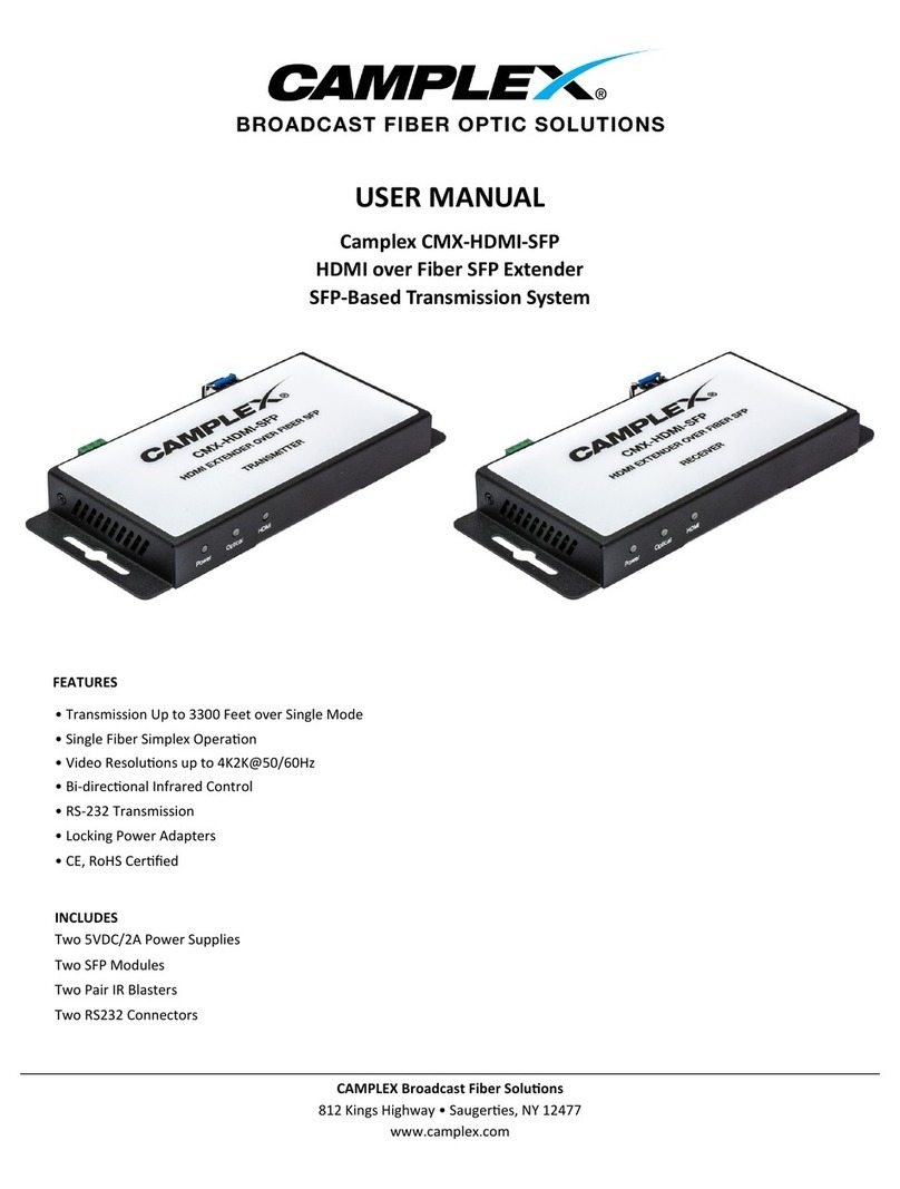
The Camplex FIBERGIGCMX‐FG600/CMX‐FG650 is a 1GIGe 802.3at/afand 2‐
Channel 3G‐SDI over singlemode fiber opc video transport
system in a rackmount enclosure with either one opcalCON quad
connector (model FG600) or four ST connectors (model FG650) and a
10/100/1000‐GIGe Ethernet media converter. The transport system is a con‐
venient rackmount soluon for transporng data and power and long haul
video extension up to 12 miles.
The system features looping outputs for every 3GSDI input for local monitor‐
ing or recording, and all outputs at receivers are dual outputs. Automac
equalizing and re‐clocking ensure a crisp, clean 3GSDI
signals over long distances. Designed for remote trucks, field producon, and
live events saving installaon me and space. A single IEC AC power cord
powers each unit which reduces the number of cables.
Includes
Two 1RU cabinets; one TX and one RX unit
Two standard 6 foot IEC type power cords
Rack screws for installaon in a standard 19” equipment rack
Features
2 Channels 3GSDI and 1 Channel [RJ45 Port] GigE
Ethernet spec meets DANTE requirements 802.3at/af
Gigabit Ethernet features up to 1000BaseT to 1000BaseX
fiber support
RJ45 to Fiber Ethernet Converter Port
Up to 30 was of power PoE Ethernet port
Convenient single rack unit enclosure with front panel connecons
Standard IEC 110/240vac 50/60Hz power inlet on back panel
Singlemode fiber connecons
Automac cable equalizaon and re‐clocking
Extends transmission capability up to 12 miles (20km)
Camplex CMX‐FG600/CMX‐FG650 Page 2
Camplex CMX‐FG600/CMX‐FG650 Page 3
CMX-FG600/FG650
Specificaons
Supports SDTV (143‐540Mbps) and HDTV (1.485Gbps,
and 3Gbps, 1080p60) image resoluons
802.3at/802.3af PoE standards compliance
SMPTE 424/292M/259M standards, DVB‐ASI
Video Connector = 75ΩBNC
Supports signal type: 270Mbit/s to 3Gbit/s
Black anodized aluminum housing
Rugged Neutrik/Senko connectors
Camplex FiberGig Series
CMX‐FG500
2 Ch 3G‐SDI,
CMX‐FG550
2 Ch 3G‐SDI,
CMX‐FG650
2 Ch 3G‐SDI & GIG‐E,
CMX‐FG600
2 Ch 3G‐SDI & GIG‐E,
CMX‐FG750
CMX‐FG700
2 Ch GIG‐E,

Camplex CMX‐FG600/CMX‐FG650 Page 4
CMX-FG600 Features
Transmier
2345678
Receiver
1
910111213141516
CMX‐FG600Transmier
1Power Switch
2Status LED Indicators
3Link 1 Input 1
4Link 1 Loop Output
7802.af/at Media I/O
8opcalCON Quad I/O
6Link 2 Loop Output
5Link 2 Input 2
15802.af/at Media I/O
16opcalCON Quad I/O
14Link 2 Output B
13Link 2 Output A
CMX‐FG600Receiver
9Power Switch
10Status LED Indicators
11Link 1 Output A
12Link 1 Output B

Camplex CMX‐FG600/CMX‐FG650 Page 5
CMX-FG650 Features
15802.af/at Media I/O
16Four ST I/O
14Link 2 Output B
13Link 2 Output A
Receiver
Transmier
12345678
910111213141516
CMX‐FG650Receiver
9Power Switch
10Status LED Indicators
11Link 1 Output A
12Link 1 Output B
7802.af/at Media I/O
8Four ST Connectors
6Link 2 Loop Output
5Link 2 Input 2
CMX‐FG650Transmier
1Power Switch
2Status LED Indicators
3Link 1 Input 1
4Link 1 Loop Output

CMX-FG600/FG650 Features
Back Panel
CMX-FG600/650 Set Up Instructions
1. Secure the units in a safe locaon, where they will not be subject to im‐
pact and where there is room around the unit so nothing will interfere
with the fiber opc cabling causing it to bend sharply in a ght radius in
any way which can severely affect the signal transfer.
2. Carefully connect your source(s) to the transmier input(s) and the re‐
ceiver unit output(s) to your receiving device input(s) using the BNC and
Cat 5/5e/6 UTP cable RJ45 connectors on the transmier and on the re‐
ceiver unit.
3. CLEAN* the fiber opcal cable contacts that will be used for connecng
the Tx and Rx units and aach the fiber cable to the
connecons and secure, as you would secure a bayonet BNC. While
pressing lightly in on the connector, twist it in a clockwise direcon about
1/8 to 1/4 of a turn and then release. The connector should stay inserted
and have backwards spring pressure holding the bayonet in place.
4. Connect the included power supplies to the transmier & receiver units,
and plug them both into an AC power source.
Camplex CMX‐FG600/CMX‐FG650 Page 6
Receiver
CMX‐FG600/650Transmier&Receiver
17AC Power Input 2A/110‐240VAC 50/60Hz
17
17
Transmier

Camplex CMX‐FG600/CMX‐FG650 Page 7
* CLEAN: All fiber opcal cable contacts (the end that is inserted and makes
contact to enable light wave transmission through the fiber)
require cleaning each me before inserng into a device’s outputs or inputs.
Failure to clean the contacts can damage the unit’s opcs over me and also
render the cable and the device nonoperaonal.
Use cleaning kits designed specifically for fiber opcs. Other cleaners may
add contaminants not seen by the naked eye which could damage cables
and/or equipment.

SAFETY PRECAUTIONS
1. To prevent fire or shock hazard, do not expose this equipment to
high humidity and/or dust. Do not use in an unprotected outdoor
installaon nor any area classified as overly damp.
2. The temperature for installaon should be kept between 32°F to
140°F (0°C to 60°C). Avoid direct sunlight exposure or extreme
changes of temperature over a short period of me.
3. Do not disassemble the unit or place it on an unstable base.
4. Do not drop the unit and avoid heavy impact.
5. This unit should not be permanently installed unless proper ven‐
laon is provided. Any enclosure openings must not be blocked or
covered as they protect the unit from overheang.
6. Before cleaning, turn offthe power and unplug the unit from all
connecons. Use a damp cloth. Do not use liquid or
aerosol cleaners.
7. Do not overload outlets and extension cords as this may
result in a risk of fire or electric shock.
8. Enclosure entry is dangerous. Never push objects of any kind, in‐
cluding liquids, into this unit through openings as they may touch
dangerous voltage points or short‐out parts that could result in a
fire or electric shock.
9. Do not aempt to open or service this unit yourself as
opening or removing covers may expose you to dangerous voltage
and other hazards.
10. There are no user‐serviceable parts inside the unit. If the unit re‐
quires service contact your authorized dealer, or an
authorized repair service company.
Camplex
812KingsHighway
Saugeres,NY12477
www.camplex.com
This manual suits for next models
1
Table of contents
Other Camplex Extender manuals

Camplex
Camplex CMX-FMCH001 User manual

Camplex
Camplex CMX-FMCH003-T User manual

Camplex
Camplex CMX-HDMI-SFP User manual

Camplex
Camplex CMX-12GSDI-TR User manual

Camplex
Camplex CMX-3G-4SDI User manual

Camplex
Camplex CMX-HDMI-SM-TR User manual

Camplex
Camplex CMX-HDMI-SFP User manual

Camplex
Camplex CMX-HDMI-SFPL User manual