Canbuilt OPT-5405 User manual

Model OPT-5405
Canbuilt Mfg.
Perfect Night Vision.....
Ver 210504
Professional
Optical Headlight Aiming System

Forewords
Canbuilt Mfg.
Perfect Night Vision.....
Thank you for purchasing the Panther OPT-5405 Optical Headlight Aimer.
You have made a wise purchase decision. The OPT-5405 is a high quality, durable piece of equipment that will give you years of trouble
free operation.
Your aimer has over 25 years of engineering refinement built-in. It is designed to meet the following requirements:
Designed for compliance with the latest revisions of the Standards SAE J599 (Aug 1997) and J600 (Feb 1993).
Aims all headlights including Domestic, European, and Asian type headlights.
Laser guided floor slope compensation.
Simple operation.
Easily transportable from bay to bay.
Requires no floor track.
Built-in self-checking for orthogonality of its components.
The aiming is performed based on an image of the headlight beam recreated inside the optical aimer head. The internal screen duplicates
the screen required by the SAE standard J599.
This manual is written based on the requirements of the SAE J599 standard for headlight aim.
Forewords
THE PANTHER OPTICAL HEADLIGHT AIMER MODEL OPT-5405

Page 2 - Assembling the Aimer
3
5
1
2
7
4
10
6
9
11
8
Assembling the Aimer
1. Optical aimer head
2. Heavy-duty mast
3. Reinforced base with wheels
4. Hardware to attach the mast to the base:
1 Bolt DIN 912, M 10 x 60
1 Washer DIN 7980, 10 mm
1 Flat washer, 10 mm
5. Lateral alignment visor
6. Lock / unlock mechanism
7. Mast cap
8. Precision floor slope compensation system
9. Aimer positioning system
10. Floor slope register
11. Laser guided floor slope measurement system (not shown)
COMPONENTS
B BA
fig. 7 pointer system
fig. 8
Attach the holder to the middle of
the aimer head, at the tip of the
pointer.
fig. 6
Hardware for Pointer
Positioning System
Install the pointer positioning system using hardware as
shown in fig. 7.
Hardware is attached to the optical aimer head and must be
removed for pointer installation fig.6.
STEP 1
Insert knob A through washer B,eye in pointer system and hen
insert another washer B.
Install assembly on optical aimer head tightening knob A
against aimer as shown in figure 7.
Canbuilt Mfg.
Perfect Night Vision.....

Check that the mast is correctly positioned. The aimer head
should be parallel to the base (fig. 4). Tighten the mast bolt
with 10 mm allen wrench.
fig. 4
Fig. 3
PUSH
fig. 1
CORRECT
INCORRECT
fig. 2
fig. 5
Bolt the mast to the base aligning the mast as shown in fig. 1.
STEP 2
Assembling the Aimer
Install optical aimer head on mast as shown in fig.2 by
pressing trigger lock (fig. 3) and sliding it down the mast.
STEP 3
Install the lateral alignment visor (fig. 5). The narrow slot in
the visor should face the rear of the aimer (the wide slot faces
the front).
Page 3 - Assembling the Aimer
ASSEMBLY IS COMPLETE
The Panther is factory calibrated for accuracy, to verify calibration of aimer, see section on aimer calibration.
STEP 5
STEP 4
Canbuilt Mfg.
Perfect Night Vision.....

Position aimer at front of bay. Switch on laser by pushing button on laser housing. Measure center of laser beam height from floor at front
wheel and at back wheel. The distance from the floor should be the same. If it is not, adjust floor slope knob until they are equal. See fig.
16 and fig. 19. The laser has a built in timer and turns off automatically.
Calibrating the Floor
Floor compensation is required.
Vehicle and aimer are both located on a flat and level floor.
INITIAL FLOOR SLOPE COMPENSATION
Vehicle and aimer are both located on a flat floor with a
constant slope.
Floor compensation is required.
Vehicle and aimer are located on different flats, both of them
with a constant slope.
Floor compensation is required.
Vehicle and/or aimer are located on irregular flats.
It is recommended not to aim the headlamps on such
floors.
LASER GUIDED FLOOR SLOPE COMPENSATION SYSTEM
CAUTION
AVOID EXPOSURE - LASER LIGHT
IS EMITTED FROM THIS APERTURE
LASER RADIATION
DO NOT STARE
INTO BEAM
POWER OUTPUT < 1mW
WAVELENGHT: 630-680 nm
CLASS II LASER PRODUCT
fig. 16
RECORDING THE FLOOR SLOPE SETTING
Floor slope adjustment knob
9
8
7
6
5
4
3
2
1
…
†
fig. 19
Near the floor slope adjustment knob , there is a register consisting of a small cylinder that can be used to count the turns of the knob .
… …
This register sinks or raises with each turn of the knob (fig. 19).
Shops using the aimer in more than one location should record the floor slope settings for each location.
ONCE THE SETTING IS RECORDED, IT IS NOT NECESSARY TO TAKE THE FLOOR SLOPE MEASUREMENT AGAIN FOR THIS
LOCATION.
Use the recorded floor slope setting for subsequent uses in the same location. Simply set the slope adjustment knob to the previously
recorded position prior to aiming headlights.
Bay No. Register Knob
Page 4 - Calibrating the Floor
Record floor slope information here for future reference.
Canbuilt Mfg.
Perfect Night Vision.....

Before checking the aim, the inspector shall;
FRemove ice or mud from under fenders.
FSet tire inflation pressures to the values specified on the tire sidewall or information label.
FCheck car springs for sag or broken leaves.
FSee that there is no load in the vehicle other than the driver.
FCheck functioning of any automatic vehicle leveling systems and specific manufacturer's instructions pertaining to vehicle
preparation for headlamp aiming.
FClean lenses and aiming pads.
FCheck for bulb burnout, broken mechanical aiming pads, and proper beam switching.
FStabilize suspension by rocking vehicle sideways.
FMeasure the vertical height of the center of the headlamp from the ground.
Vehicle Preparations
PREPARING THE VEHICLE FOR HEADLAMP AIM OR INSPECTION
Rotate aimer positioning system (pointer) to front of aimer. Move aimer so that positioning pointer is at center of headlight beam. The
pointer can be stored as shown with dashed lines in illustration, when not in use.
Note: There are several ways to determine the center of the headlight beam. If your headlight has a clear lens and you can see the bulb, it
is generally located at the center. Some headlight lenses have a small dot in the lens that indicates the center. Many light beams have a
“dark spot” in the center of the beam, this can be easily found by placing a cloth over the light and turning on the headlights.
Place the aimer in front of one headlamp at a distance between 10 to 14 in. (25 to 35 cm). Most beam patterns are clearest if the optical
lens is about 12” from the lamp surface.
Page 5 - Vehicle Preparations
25-35 cm
10-14 in
fig. 20
Side view Top View
Canbuilt Mfg.
Perfect Night Vision.....

CORRECT
Aimer is ready to test headlight. Turn on headlights and use internal screen to aim the light. Correct beam positioning on the aiming
screen is explained on the following pages. Proper aim for high beams, low beams, Euro beams, driving lights, and fog lights are
explained.
INCORRECT
CORRECT
INCORRECT
fig. 21
The Panther has markings drawn on the aimer which can also be used for positioning the aimer at the center of the
headlight. These markings can be used instead of the pointer if desired. Laser can also be used for vertical centering. See
drawings below.
Align with center of beam
Vehicle Preparations
OPTIONAL METHOD OF POSITIONING AIMER
POSITIONING AIMER TO VEHICLE
With aimer in front of the headlight, choose two symmetrical points of the vehicle located also at the same height (i.e. the upper part of the
lamps, strut bolts, radiator support bolts).
Points located too high, such as the vehicles roof, should be avoided: the best accuracy is obtained using lower points.
Looking through the lateral alignment visor, make both points lie on the visor's wire, by slightly moving the aimer, Fig.21.
Page 6 - Vehicle Preparations
Align with center of beam
Canbuilt Mfg.
Perfect Night Vision.....
Lift Here
Professional Optical
Headlight Aiming System
Canbuilt Mfg.
Perfect Night Vision...
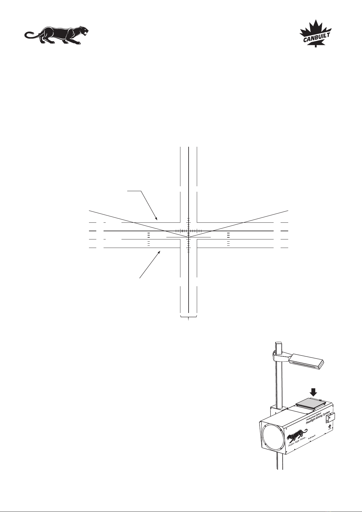
The Panther 5405 is designed to reproduce, at a smaller scale, an aiming test screen compliant with the Standard SAE J599
(revised Aug. 1997). The beam projections appear on the internal screen of the aimer as they would appear on a screen located 25
feet from the headlamps.
The aiming screen complies with all aiming and inspection requirements of the Standards SAE J599 (revised August 1997) and SAE J600
(revised February 1993).
With the lines drawn on the internal screen of the aimer, all aiming and testing procedures can be performed according to the inspection
limits described in the Standards.
In addition, the European type lighting can also be aimed.
Aiming Procedures
DESCRIPTION OF THE INTERNAL SCREEN OF THE AIMER
Horizontal line used as low beam
inspection upper limit.
Biased line for the
European type low beam
Horizontal line used as low
beam inspection lower limit.
Two vertical lines used as low beam lateral inspection limits
100 mm
100 mm
100
mm
100
mm
4" 4"
4"
4"
8"
0"
4"
4"
8"
0"
Due to the widely varying light intensity and color of automotive headlights, and different
operators sensitivity to light, it is difficult to locate the light beam pattern when adjusting
headlights on some vehicles. Canbuilt has developed a beam elucidation filter to make it easier
to view these beam patterns. The filters are designed to remove some of the extraneous light
from the viewable pattern and enhance the high intensity zone, providing an image that is
clearer and easier to see.
To use the filter, simply set it on top of the aimer body above the viewing window. The magnetic
strips will hold it in place. For best operation, the magnetic strips should be toward the front and
rear of the aimer. Choose the filter (or filters) that works best for your vision.
The filters can be stored by using the magnetic strips to attach them any place on the metal
aimer head.
BEAM ELUCIDATION FILTERS
Place filter over viewingPlace filter over viewing
window herewindow here
Place filter over viewing
window here
Page 7 - Aiming Procedures
Canbuilt Mfg.
Perfect Night Vision.....

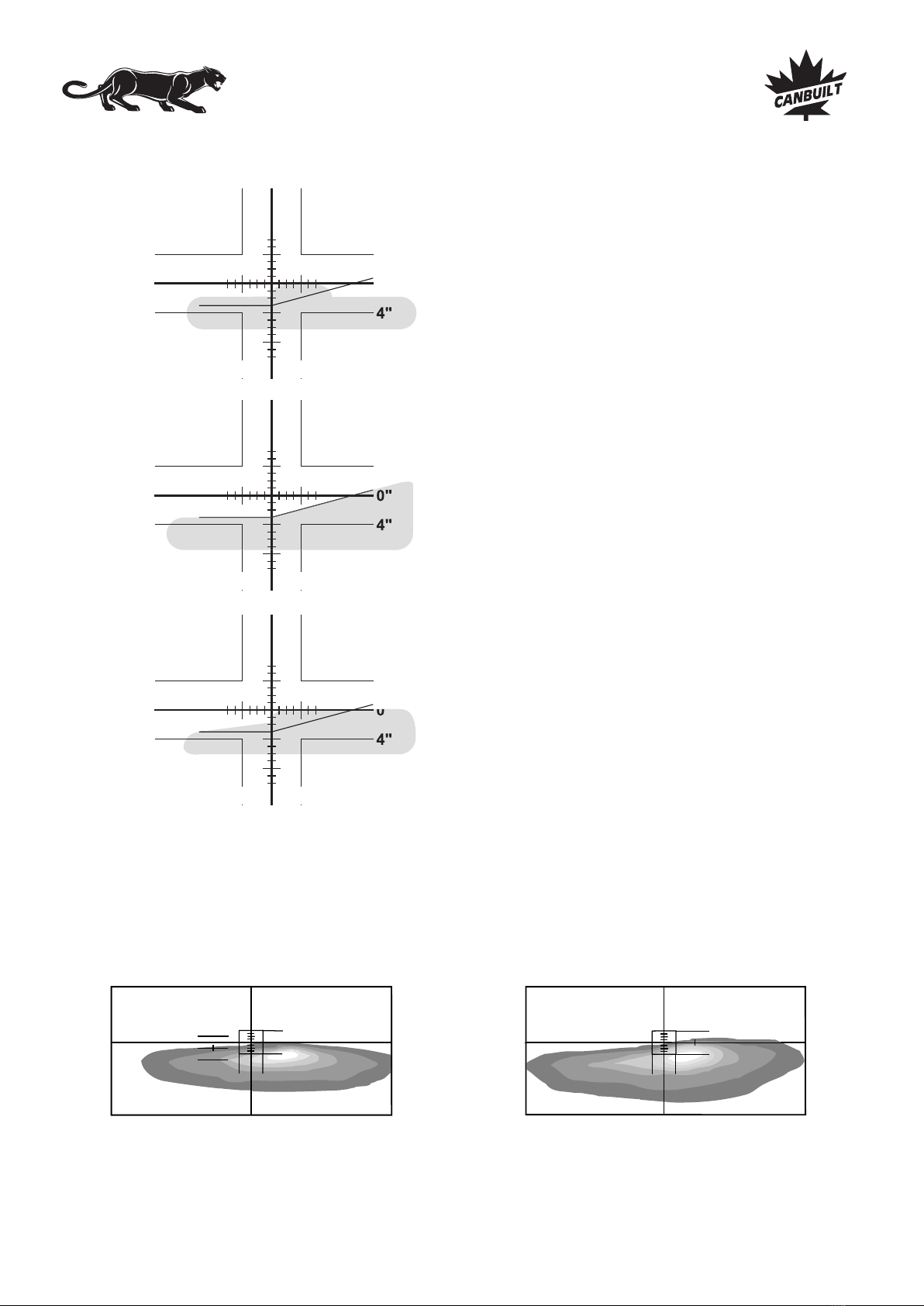
The inspection limits are a range of 4” at 25’. The illustrations below show the range allowed for vertical and horizontal inspection.
The left side of the “high intensity zone” must fall within the shaded
area for proper low beam horizontal adjustment.
The top of the “high intensity zone” must fall within the shaded area
for proper low beam vertical adjustment.
Nominal Vertical Aim Line
100 mm
100 mm
100
mm
100
mm
4" 4"
4"
0"
4"
8"
Inspection
upper limit
Inspection
lower limit
4"
0"
4"
4" 4"
Inspection
left limit
Inspection
right limit
4"
0"
4"
4" 4"
Low Beam Headlamps are aimed so that the top edge of the
high-intensity zone is at the NOMINAL VERTICAL AIM line,
and the left edge of the high-intensity zone is at the vertical
center line of the screen.
NOTE: Headlights centered more than 36” from the ground require beam slope compensation. See page 12 for details.
AIMING LOW BEAM HEADLAMPS
INSPECTION LIMITS FOR LOW BEAM HEADLIGHTS
There are many different beam patterns used in domestic vehicles. When checking headlights with complicated beam
patterns, you must locate the part of the high intensity zone that shines farthest down the road (is highest on the
screen) . This generally appears as a “hump” in the beam pattern. Once this is located, you simply set the left edge of
the “hump” to align with the center cross hair on the screen. You set the top of the “hump” with the horizontal cross hair.
The bottom of the “hump” typically blends into the lower portion of the beam pattern and is not considered when
adjusting the headlight.
Aiming Procedures
DIFFERENT LOW BEAM PATTERNS
Page 8 - Aiming Procedures
Canbuilt Mfg.
Perfect Night Vision.....
4"
0"
4"
4" 4"
4"
0"
4"
4" 4"
4"
0"
4"
4" 4"
From 1999 on, some vehicles have lenses called “Visual Optical Left (VOL)” and “Visual Optical Right (VOR)”. The top of the beam
patterns on these lights are aimed based on each design.
VOL headlights are aimed on the left side of the screen. The top of the beam should be ste .4 degrees (2.096”) below the horizontal center
line left of the vertical center..
VOR headlights are aimed on the right side of the screen. The top of the beam should be set at the center horizontal line.
Vertical aiming area
VOL
Vertical aiming area
VOR
Aiming Procedures
Many composite headlights do not have a distinct “high
intensity zone”. When adjusting these lights you must locate the
area in the beam pattern that rises above the rest of the beam.
This part of the pattern shines farthest down the road and is
considered the “high intensity zone”.
Many late model headlights have patterns similar to the
European beam pattern. You should set these headlights
using the biased line as shown.
Some patterns do not have a distinct edge on the right side.
When aiming this type of headlight, ignore the right side of the
pattern. Simply locate the left edge of the high intensity area
that shines farthest down the road. This should be adjusted to
the centerline on the aiming screen. The top edge will normally
be easy to locate.
Vertical position of VOR Headlights is adjusted at the horizontal
center line of the aiming screen at the area just to the right of the
vertical center line of the screen.
Vertical position of VOL Headlights is adjusted .4 degrees
(2.096”) below the horizontal center line of the aiming screen at
the area just to the left of the vertical center line of the screen.
VISUAL OPTICAL BEAM PATTERNS
Page 9 - Aiming Procedures
Canbuilt Mfg.
Perfect Night Vision.....
Other manuals for OPT-5405
1
Table of contents
Other Canbuilt Flashlight manuals


