Canbuilt OPT-5405 User manual
Model OPT-5405
Ver 050720
Professional
Optical Headlight Aiming System
Canbuilt Mfg.
Perfect Night Vision.....


Index
INDEX
Aiming Low Beams 14
Aiming High Beam and Auxiliary Lights 17
Aiming Fog Lights 18
Aiming European Beam 19
Forewords 3
Assembling the aimer 4
Calibrating the Floor 7
Floor Slope Register 8
Vehicle Preparations 9
Positioning Aimer to Vehicle 10
Beam Slope Compensation 20
Calibrating the aimer 21
Warranty Information 27
Aiming Procedures 12
The Aiming Screen 12
Beam Elucidation Filters 13
Canbuilt Mfg.
103 Milvan Dr.
Toronto, Ontario
Canada M9L 1Z7
(416) 749-6555
www.canbuilt.com
Index - Page 1
Canbuilt Mfg.
Perfect Night Vision.....


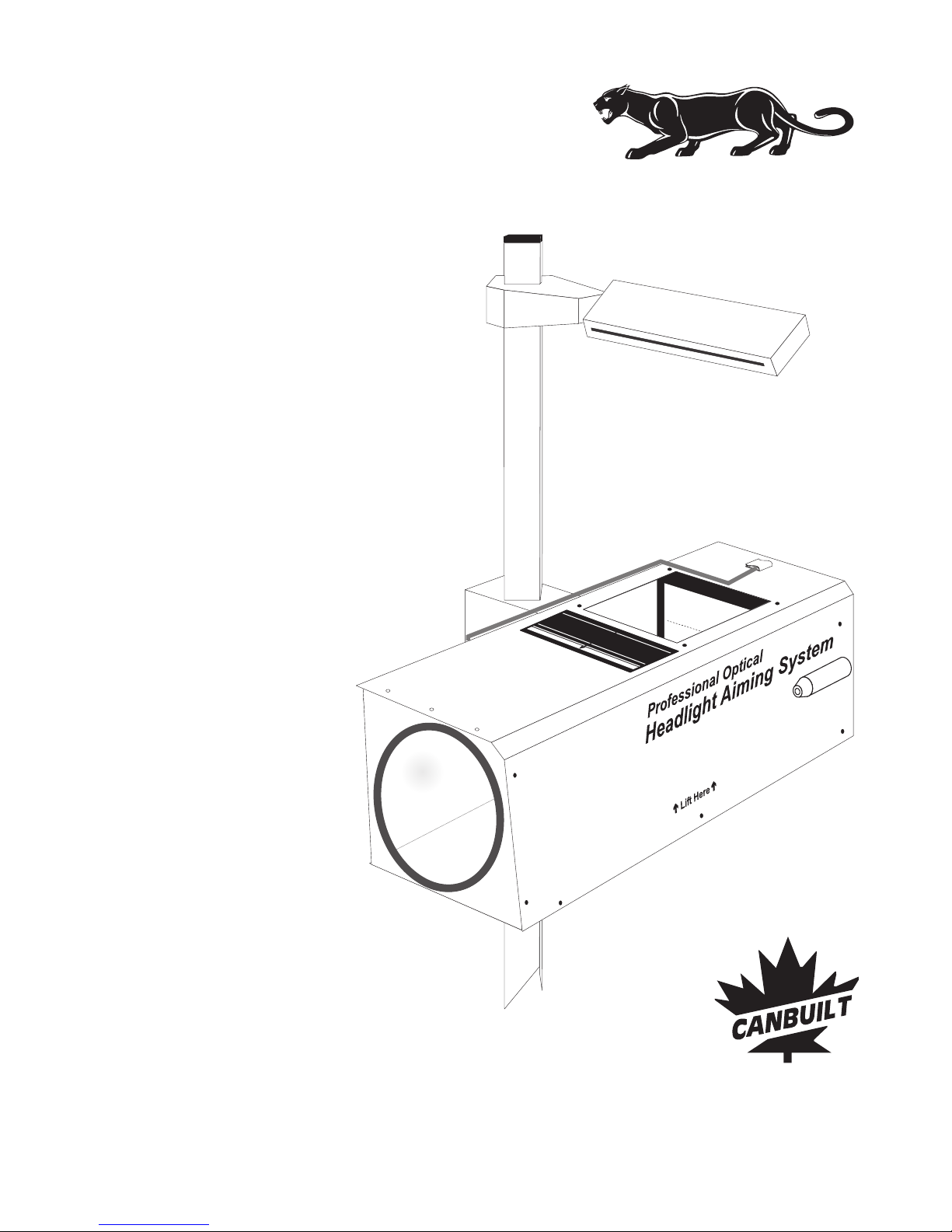
THE PANTHER OPTICAL HEADLIGHT AIMER MODEL OPT-5405
Thank you for purchasing the OPT-5405 Optical Headlight Aimer.Panther
You have made a wise purchase decision. The OPT-5405 is a high quality, durable piece
of equipment that will give you years of trouble free operation.
Your aimer has over 25 years of engineering refinement built-in. It is designed to meet the
following requirements:
Designed for compliance with the latest revisions of the Standards SAE J599 (Aug 1997)
and J600 (Feb 1993).
Aims all headlights including Domestic, European, and Asian type headlights.
Laser guided floor slope compensation.
Simple operation.
Easily transportable from bay to bay.
Requires no floor track.
Built-in self-checking for orthogonality of its components.
The aiming is performed based on an image of the headlight beam recreated inside the
optical aimer head. The internal screen duplicates the screen required by the SAE
standard J599.
This manual is written based on the requirements of the SAE J599 standard for headlight
aim.
Forewords
Forewords-Page 3
Canbuilt Mfg.
Perfect Night Vision.....

COMPONENTS:
1
2
3
4
5
6
. Optical aimer head
. Heavy-duty mast
. Reinforced base with wheels
. Hardware to attach the mast to the
base:
1 Bolt DIN 912, M 10 x 50
1 Washer DIN 7980, 10 mm
1 Flat washer, 10 mm
. Lateral alignment visor
. Lock / unlock mechanism
. Mast cap
. Precision floor slope compensation
system
7
8
9
10
11.
. Aimer positioning system
. Floor slope register
Laser guided floor slope
measurement system (not shown)
3
5
1
2
7
4
8
0
9
8
7
6
5
4
3
2
1
10
Assembling the Aimer
6
9
11
Page 4 - Assembling the Aimer
Canbuilt Mfg. Perfect Night Vision.....

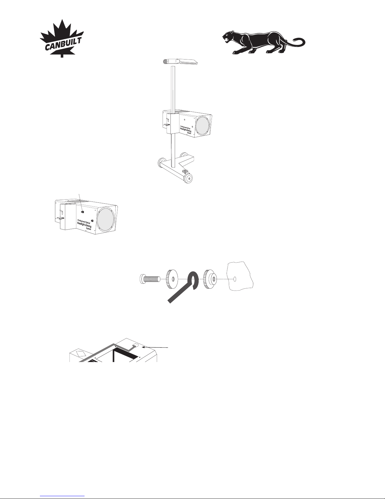
Assembling the Aimer
STEP 1
Bolt the mast to the base aligning the mast as shown in
fig. 1.
STEP 2
Install optical aimer head on
mast as shown in fig.2 by
pressing trigger lock (fig. 3)
and sliding it down the mast.
Fig. 1
STEP 3
Check that the mast is correctly positioned. The aimer head should be parallel to the
base (fig. 4). Tighten the mast bolt with 10 mm allen wrench.
Fig. 4
CORRECT INCORRECT
Fig. 2
Fig. 3
Assembling the Aimer - Page 5
Canbuilt Mfg.
Perfect Night Vision.....
Assembling the Aimer
ASSEMBLY IS COMPLETE
The Panther is factory calibrated for accuracy, to verify calibration of aimer, see section
on aimer calibration.
Attach the holder to the middle of
the aimer head, at the tip of the
pointer.
Fig. 5
STEP 4
Install the lateral alignment visor (fig. 5). The
narrow slot in the visor should face the rear of the
aimer (the wide slot faces the front).
STEP 5
Install the pointer positioning system using
hardware as shown in fig. 7. Hardware is attached
to the optical aimer head and must be removed for
pointer installation fig.6.
fig. 6
Hardware for Pointer
Positioning System
Thread nut on bolt , insert
through eye in pointer system and
thread nut on bolt . Install
assembly on optical aimer head
tightening nut against aimer as
shown in fig. 7.
Repeat the process for stopper pin.
BA
CA
C
fig. 8
Page 6 - Assembling the Aimer
fig. 7
CB
A
pointer system
Canbuilt Mfg. Perfect Night Vision.....

Calibrating the Floor
INITIAL FLOOR SLOPE COMPENSATION
Vehicle and aimer are both located
on a flat and level floor.
Floor compensation is required.
Fig. 12
Vehicle and aimer are both located
on a flat floor with a constant slope.
Floor compensation is required.
Fig. 13
Vehicle and aimer are located on
different flats, both of them with a
constant slope.
Floor compensation is required.
Fig. 14
Vehicle and/or aimer are located on
irregular flats.
It is recommended not to aim the
headlamps on such floors.
Fig. 15
LASER GUIDED FLOOR SLOPE COMPENSATION SYSTEM
Position aimer at front of bay. Turn on laser by turning knob on laser housing. Measure
center of laser beam height from floor at front wheel and at back wheel. The distance
from the floor should be the same. If it is not, adjust floor slope knob until they are equal.
See fig. 16 and fig. 19.
Fig. 16
CAUTION
LASER RADIATION
DO NOT STARE
INTO BEAM
CLASS II LASER PRODUCT
POWER OUTPUT < 1mW
WAVELENGHT: 630-680 nm
Calibrating the floor - Page 7
Canbuilt Mfg.
Perfect Night Vision.....

Calibrating the Floor
0
9
8
7
6
5
4
3
2
1
Floor slope adjustment knob
Fig. 19
RECORDING THE FLOOR SLOPE SETTING
Near the floor slope adjustment knob , there is a
register consisting of a small cylinder that can be
used to count the turns of the knob . This register
sinks or raises with each turn of the knob (fig. 19).
Shops using the aimer in more than one location
should record the floor slope settings for each
location.
.
Use the recorded floor slope setting for subsequent
uses in the same location. Simply set the slope
adjustment knob to the previously recorded position
prior to aiming headlights.
ONCE THE SETTING IS RECORDED, IT IS NOT
NECESSARY TO TAKE THE FLOOR SLOPE
MEASUREMENT AGAIN FOR THIS LOCATION
Note: A decal is included with the aimer. You can record floor slope settings and adhere
the decal to aimer for reference. You can also use the matrix below for recording this
information.
BAY NUMBER REGISTER SETTING
REGISTER SETTING KNOB SETTINGKNOB SETTING DATE
Page 8 - Floor slope register
Canbuilt Mfg. Perfect Night Vision.....
Other manuals for OPT-5405
1
Table of contents
Other Canbuilt Flashlight manuals


