C&J DGT 5000 Owner's manual

C&J DGT5000
Suite ‘Shelf’ or ‘Slab’ Burner
Owner's Book
(THIS APPLIANCE IS FITTED WITH ALKALINE BATTERIES)
I CLUDES USER, I STALLATIO & MAI TE A CE
I STRUCTIO S
Please read these instructions carefully before you start using the
appliance
Keep this booklet handy for future reference
This appliance is
for use in GREAT BRITAI or IRELA only
A QUALITY PRODUCT FROM C&J FIRES

LT5032 (01:05-08)
2
C&J DGT 5000 Instructions
CONTENTS
PAGE
USER INSTRUCTIONS 3
SECTION ONE Introduction 3
Consumer Protection 3
Health and Sa ety 3
Introduction 3
SECTION TWO O erating the a liance 6
SECTION THREE Fuel Bed Cleaning and Layout 8
Coal Layout 8
Pebble Layout 9
SECTION FOUR Im ortant information 11
INSTALLATION INSTRUCTIONS 17
SECTION FIVE S ecification 12
SECTION SIX Regulations and Warnings 12
SECTION SEVEN Siting the A liance 13
SECTION EIGHT Fire lace Requirements 14
Installation cut out 14
Fireplace opening dimensions 14
Hole in the Wall installations 14
Clearance to Shel 15
Clearance to Side o Fire 15
Ventilation 15
SECTION NINE To Install the A liance 16
Examine Flue /Chimney 16
Preparing or installation 16
Connecting to the Gas Supply 16
Fixing Fire into Opening 17
Checking Gas Soundness 17
Fuel Bed Layout (Re er To User’s Section) 17
Checking Operation o Fire 17
Checking Product Clearance 18
Completion o Installation 18
Advise Customer 18
MAINTENANCE INSTRUCTIONS 19
SECTION TEN Maintenance 19
General 19
Fuel Bed Cleaning 19
Replacement o Gas Control 19
Replacement o Injector 19
Replacement o Pilot Assembly 20
Replacement o Control Unit (EDB) 20
SECTION ELEVEN Wiring Diagram 20
Warranty Cover 21

LT5032 (01:05-08)
3
C&J DGT 5000 Users Instructions
SECTION ONE Introduction
Consumer Protection Information
As manu acturers and suppliers o heating products, we take every care, as ar as is reasonably
practicable, that these products are so designed and constructed as to meet the general sa ety
requirement when properly used and installed. To this end, our products are thoroughly tested
and examined be ore despatch.
IMPORTANT NOTICE: Any alteration that is not approved by the appliance manu acturer could
invalidate the approval o the appliance, operation o the warranty and could a ect your
statutory rights.
Health and Safety Notice
Im ortant:This appliance could contain some o the materials, indicated below, that could be
interpreted as being injurious to health and sa ety. It is the users / installers responsibility to
ensure that the necessary personal protective clothing is worn when handling these materials,
see below or in ormation
.
Artificial Fuels, Mineral Wool, Insulation Material, Refractory/Ceramic Fibres, Glass Yarn -
may be harmful if inhaled, may be irritating to skin, eyes, nose and throat.
When handling
avoid inhaling and contact with skin or eyes. Use disposable gloves,
facemasks and eye protection. After handling wash hands and other exposed parts. If a vacuum
is used for cleaning the fuel bed or cleaning after servicing / installation it is recommended that
it be of the type fitted with a H PA filter
.
Dis osal of refractory/ceramic materials. To keep dust to a minimum these materials should
be securely wrapped in polythene and be clearly labelled ‘RCF waste’. These materials are not
classi ied as ‘hazardous waste and should be disposed o at a site licensed or the disposal o
industrial waste.
INTRODUCTION
•
The C&J DGT 5000 as been designed and tested to the requirements o EN 509 and is
suitable or use in GB (Great Britain) and IE (Ireland).
•
The C&J DGT 5000 incorporates a single gas control, which selects ignition pilot, with
variable setting between low and high settings. The appliance is operated via a remote
control hand set.
•
This appliance is intended or decorative purposes only.
•
The C&J DGT 5000 is available in Natural Gas. The markings (G20 or natural gas) on the
packaging and the data badge speci y the gas or which the appliance has been actory set.
Note: These appliances should only be used on the appropriate gas specified. They are not
suitable for conversion from one gas to the other.
•
The pilot can be le t on (standby setting) or the pilot can be extinguished and re-lit each time
the ire is used.
•
Like all appliances incorporating an aerated burner a low requency noise may be heard, this
may be more noticeable on the low setting.
•
The chimney or lue (unless new) must be swept be ore installation i it has been used or
solid uel.
•
It is advised that this appliance is serviced annually, this is more likely to provide trouble- ree
operation.
•
This appliance has a naked lame, as with all such ires it is recommended that a ireguard
should be used or the protection o children, the elderly and in irm. Fireguards should
con orm to BS 6539 (1984) (Fireguards or use with solid uel appliances).

LT5032 (01:05-08)
4
C&J DGT 5000 Users Instructions
SECTION ONE Introduction Continued
The C&J DGT 5000 is battery operated; there ore no mains electrical supply is required. Power
to the appliance is provided by 6 high power alkaline 1.5V batteries (AA size) (a spare set o 6
AA batteries is supplied with the appliance). Non-rechargeable high power AA Lithium type
batteries (o ten sold or digital cameras) can give even longer service. Alkaline or Lithium AA
batteries can also be changed to Nickel Metal Hydride rechargeable batteries providing they
have a minimum capacity o 2200 mAh. A set o 6 high power alkaline 1.5V batteries (AA size)
would give in the order o 200-500 operations while 6 rechargeable batteries when ully charged
would give approximately 200-300 operations. These igures are only given or guidance and
may vary depending on how the appliance is used and the battery manu acturer and quality.
A special long li e lithium battery is available as an optional extra and would be expected to give
in excess o 12 months normal use (a minimum o 1000 operations), however it is not subject to
the guarantee. A urther dedicated rechargeable battery pack is also available. For more
in ormation call the telephone number located on the back o this booklet.
Using the standby acility when the appliance is switched o or short periods can extend
battery li e. The standby acility switches o the mains gas supply to the appliance but the pilot
remains alight.
An audible double bleep warning indicates that the appliance batteries need changing or
charging (i rechargeable batteries have been used).
Im ortant: Batteries should be changed or recharged as soon as ossible as the
a liance will not light if the battery ower gets to low.
The appliance incorporates a sa ety device in the orm o an Oxygen Depletion System, which
constantly monitors the oxygen in the room and will cause the ire to switch o i the oxygen
level reduces, or instance due to insu icient ventilation or a blocked lue.
If this regularly occurs do not attempt to relight the appliance until a qualified engineer has
checked it, the problem may not be due to lack of air or a defective flue.
A ire ront ( ret) must be used with this appliance.
In GB, the appliance must be installed by a competent person i.e. CORGI-registered, in
accordance with the GAS SAFETY (INSTALLATION AND USE) REGULATIONS, The Building
Regulations (or The Building Regulations (Scotland) or The Building Regulations (Northern
Ireland)) and The Current I.E.E. Wiring Regulations, i appropriate.
In IE, the appliance must be installed by a competent person and installed in accordance with
the current edition o I.S.813 Domestic Gas Installation, the current Building Regulations and
the current ETCI rules or electrical installation ,i appropriate.
In the Republic o Ireland, permanent ventilation must be provided in accordance with the
regulation in orce (I.S. 813).
It is im ortant that: -
The chimney or lue is checked annually to ensure clearance o combustion products.
Any purpose-built ventilation should be checked periodically to ensure reedom rom
obstruction.
Any debris rom the chimney or lue should be removed. The ire should be allowed to cool or
three to our hours be ore removing debris.
Rubbish must not be thrown onto the coal/pebble bed under any circumstances.

LT5032 (01:05-08)
5
C&J DGT 5000 Users Instructions
SECTION ONE Introduction Cont.
Warning:- This appliance has a naked lame, has with all ires it is recommended that a
ireguard should be used or the protection o children, the elderly and in irm.
Fireguards should con orm to BS 6539 (1984) ( ireguards or use with solid uel appliances).
During the normal operation o the ire some staining may appear on some parts o the uel bed.
This is quite normal and adds to the appearance o the appliance. However, i excessive black
staining does occur it may be due to the uel bed being incorrectly laid. This should be checked
against the Fuel Bed Layout Section prior to contacting a service engineer.
Pilot Cleaning (Be ore cleaning ensure that the appliance is turned o and cold)
In some instances you may experience ignition problems even when the appliance is new. This
may be due to the aeration hole in the pilot body (see photograph) being partial blocked with
dust, pet hairs or other oreign matter. The source o this debris could be such things as carpet
ibres, decorating or pets etc.
To clean the pilot, remove the top grille rom the ire by removing the our securing screws. The
pilot is located on the right hand side o the appliance; any debris in or around the aeration hole
should be removed using the nozzle o a vacuum cleaner. It is advisable not to blow the debris
into the hole as this may cause more o a restriction and not recti y the problem.
1. Remove to late securing screws
2. Remove battery com artment
3. Remove to grille
4. Clean
under ilot
bracket with
vacuum
attachment to
clear aeration
hole.

LT5032 (01:05-08)
6
C&J DGT 5000 Users Instructions
SECTION TWO O erating the A liance
Before attem ting to o erate the a liance check that nothing has been laced in front of
the a liance that may interfere with the remote sensor o eration.
To light the a liance using the remote hand set:
a. Point the remote control hand set in the direction o the
appliance and simultaneously press the buttons marked
‘’ and ‘standby’. Continue to hold in these two buttons
until a ‘bleep’ is heard (approximately 2-3 sec.) and
then release these buttons. The appliance will
automatically go through the ignition sequence and the
pilot should ignite. Once the pilot is alight the appliance
will automatically go to the high setting (approximately
20-25sec). I the ignitor stops sparking and the pilot ails
to light, repeat this procedure.
b. I the ignitor stops sparking and the pilot ails to light
press the
' '
button be ore repeating this procedure.
c. The appliance can be adjusted up or down by pressing the
appropriate button
' '
(low setting) or
' '
(high setting). These buttons have a duel
unction. I they are pressed until a ‘bleep’ is heard and then released immediately the
appliance will automatically go to the maximum
' '
or minimum settings
' '
. On the other
hand i the button is not released, gradual adjustment is made until the button is released or
until the maximum or minimum setting is reached.
d. To switch o the appliance press the
' '
button or i the appliance is to be switch o or a
short period it is recommended that the ‘standby’ button be used. This switches the main
burner o but leaves the pilot on and will extend battery li e.
e. The appliance can be switch o with out using the hand set by removing the appliance
batteries located behind the ash pan cover. When the batteries are removed there will be a
delay (up 3minutes) a ter which double bleeps may be heard and shortly a ter the appliance
will extinguish. Ensure that the battery is reconnect once the ire as been extinguished. The
appliance cannot be operated without the use o the handset.
NOTE: If the fire is extinguished for any reason wait 3 minutes before relighting.
Low Battery Indication (Hand Set)
I while pressing any o the buttons on the remote hand
set the low battery indicator lamp either stops lashing or
appreciably slows then the battery should be changed.
To Re lace Battery In Hand Set (9v PP3 Size
Mn1604 Or 6f22)
Remove the cover rom the rear o the handset and it
replacement battery. Take care not to stain the battery
connections.

LT5032 (01:05-08)
7
C&J DGT 5000Users Instructions
SECTION TWO O erating the A liance Continued
Low Battery Indication (A liance)
I you hear a double ‘bleep’ sound come rom the appliance this indicates the appliance battery
pack is low and should be changed as soon as possible. The appliance will continue to work
normally or a short period but i the warning is ignored you may experience di iculty lighting the
appliance or the appliance may automatically switch o or no apparent reason.
NOTE: The appliance cannot be used when the battery is completely lat.
To re lace a liance batteries (6 high ower alkaline AA 1.5v)
(Rechargeable batteries can be used roviding they are a nickel metal hydride ty e 1.5V
AA with a minimum ca acity of 2200mAh).
(A long life lithium battery is available as an o tional extra call the number shown on the
last age of these instructions for further information).
a. The battery power pack holder is located at the le t hand
side o the burner; care ully li t out the battery holder and
replace the six high power alkaline AA batteries as a
complete set or recharge as appropriate. WARNING,
batteries will overheat if fitted incorrectly, when
fitting the batteries ensure that they are fitted as er
the marking on the rear of the holder (i.e. minus of
battery against s ring). I rechargeable batteries are
used they MUST be a Nickel Metal Hydride type with a
minimum capacity o 2200mAh or the dedicated
rechargeable system supplied by C&J.
b. I the appliance is
itted with the
special lithium
battery (optional)
disconnect the
wires at the
battery connector
and replace ensuring the connection is
made correctly.
c. Im ortant: Place the battery pack or holder into the holder tray on the le t side o the
irebed. Take care not to strain the leads.
SECTION THREE Fuel Bed Cleaning and Layout
Im ortant: - Refer to the ‘Health & Safety Notice located on page 3 of this
booklet before cleaning or replacing any refractory material.
The uel bed components are delicate and they should be handled with great care.
The loose parts and moulded shapes may be removed or cleaning. They can be brushed very
gently with a so t brush to remove dust or any deposits.
A vacuum cleaner may only be used a ter the loose components and moulded shapes have
been removed.
CARE SHOULD BE TAKEN TO AVOID CONTACT WITH THE REFRACTORY LINING THIS IS
A DELICATE SURFACE AND SHOULD NOT BE WIPED OR RUBBED.

LT5032 (01:05-08)
8
C&J DGT 5000 Users Instructions
FUEL BED LAYOUT (GRANULAR FIRE BED OPTION)
•
Place the black or white granular burner
bed material in position in the burner tray
as shown. DO NOT place granular
materials over the top grille o the burner
unit as it will drop through, block the grille,
cause overheating o internal components
and potentially dangerous shortage o
combustion air. Keep the area around the
pilot head clear o granules to ensure good
cross lighting.
FUEL BED LAYOUT (COAL OPTION)
• One or two packs o 17 coals can be
used to enhance the uel bed on the DGT
5000 burners. The irst pack o coals
must be places on the burner as shown.
The second pack o coals must be placed
around the burner as shown, NOT on the
top o the irst pack.
• Place the irst row o 6 coals along the
back o the granular material in the
burner tray as shown.
• Place the second row o coals along the
ront o the ront o the burner tray as
shown.
Make sure area around ilot is clear
of granular materials for smooth
cross lighting.

LT5032 (01:05-08)
9
C&J DGT 5000 Users Instructions
SECTION THREE Fuel Bed Cleaning and Layout Cont.
•
Place the inal row o ive coals bridging
between the back and ront row o coals to
orm a inal top layer as shown. DO NOT
lay any urther coals or pebbles on top o
the burner area o the ire.
FUEL BED LAYOUT (EXTRA COAL OPTION)
•
An extra pack o 17 coals can be
obtained to lay around the burner unit
grille as shown. Leave plenty o air
gaps between the coals to ensure that
the cooling air low to the underside o
the burner is not impeded in any way.
DO NOT place these coals on top o
the combustion area o the burner.
•
The inished coal arrangement should
look as shown.
Note Dye is available or touching up coal
sur aces where the black colouring may
have rubbed o in use.
FUEL BED LAYOUT (PEBBLE OPTION)
•
Place 6 pebbles on to the back o the
granular burner bed material as shown.

LT5032 (01:05-08)
10
C&J DGT 5000 Users Instructions
SECTION THREE Fuel Bed Cleaning and Layout Cont.
•
Place a ront row o 6 pebbles on to the ront
o the granular bed as shown..
• Place the inal top row o 5 pebbles
bridging between the irst low two rows.
DO NOT lay any urther coals or pebbles
on top o the burner area o the ire
FUEL BED LAYOUT (EXTRA PEBBLE OPTION)
•
An extra pack o 17 pebbles can be
obtained to lay around the burner unit
grille as shown. Leave plenty o air
gaps between the pebbles to ensure
that the cooling air low to the
underside o the burner is not impeded
in any way. DO NOT place these extra
pebbles on the combustion part o the
ire bed although they can bridge to the
ront row o pebbles only.
The inished pebble arrangement should
look as shown.

LT5032 (01:05-08)
11
C&J DGT 5000 Users Instructions
SECTION FOUR Im ortant Information
The only user removable parts are: -
•
The loose pebbles or coals.
•
Battery compartment and batteries
•
Top grille section o the ire
Like all appliances incorporating an aerated burner a low requency noise may be heard,
particularly on the low setting, this is quite normal and does not a ect the operation o the
appliance.
Servicing
It is advised that the C&J DGT 5000 ire is serviced annually this is more likely to provide
trouble- ree operation. A competent person must carry this out, i.e. CORGI Registered
Installer in accordance with the current Gas Sa ety (Installation and Use) Regulations 1998
(as amended).
The chimney or lue should be checked annually to ensure clearance o combustion
products.
Ventilation in the United Kingdom
This appliance does not normally require purpose-built ventilation but i or any special
reason purpose-built ventilation is provided it should be checked periodically to ensure
reedom rom obstruction.
Ventilation in the Republic o Ireland
Must be permanent ventilation and must comply with the rules in orce and should be
checked periodically to ensure reedom rom obstruction.
General Appliance Care
Any debris rom the chimney or lue should be removed rom the uel bed. The ire should
be allowed to cool or three to our hours be ore removing debris.
Rubbish must not be thrown onto the uel bed under any circumstances. The cast ire ront
must be positioned in ront o the ire whilst it is burning.

LT5032 (01:05-08)
12
C&J DGT 5000 Installation Instructions
SECTION FIVE S ecification
NATURAL GAS
Category o Appliance: B
AS
Category I
2H
Gas type: G20
Gas Pressure: 20 mbar
Gas input high: 7.00 kW Gross
Gas input low: 2.40 kW Gross
Injector Main: Size 460
Oxy-pilot NG9102
Batteries
Remote handset 9v size PP3, MN1604 or 6F22, Appliance 6 x 1.5V
AA high power alkaline/Lithium or 6 x 1.5 V rechargeable nickel metal hydride with a minimum capacity o
2200mAh. A special long li e lithium battery 7.2 V is available as an optional extra together with a dedicated
rechargeable system.
Data Label Location: Behind trim
Gas Connection: 8 mm OD Tube
SECTION SIX Regulations and Warnings
• THIS APPLIANCE MUST ONLY BE INSTALLED IN THE GB OR IRELAND.
• Only to be used in su iciently ventilated room. Read instructions care ully be ore
installation and use. The appliance must be installed by a competent person, i.e..
CORGI Registered Installer in accordance with the current Gas Sa ety (Installation and
Use) Regulations 1998 (as amended). Failure to do so could lead to prosecution.
• This C&J DGT 5000 is or use ONLY with the GAS STATED ON THE DATA BADGE
this will be G20 for Natural Gas CHECK YOU HAVE THE CORRECT APPLIANCE
FOR THE GAS YOU ARE USING.

LT5032 (01:05-08)
13
C&J DGT 5000 Installation Instructions
SECTION SIX Regulations and Warnings Continued
• It can be used in conjunction with the ollowing chimneys: -
• A conventional brick or stone chimney,
• A metal lue and box con orming to BS 715, urther details are covered in later text.
• A non-combustible hearth must be provided to comply with the building regulations or a
suitable proprietary ire surround with a 100 degrees C rating.
• During initial iring an odour may be evident. This is the binder used during the
manu acture o the ibre components and there are no harm ul e ects produced.
The ollowing are the relevant Codes o Practice and British Standards: -
BS 5871 BS 8303
BS 5440 part 1 BS 1251
BS 6891 BS 6461 parts 1 & 2
BS 715 BS 1289 part 1& 2
Note:- This a liance must be installed to current versions of the above standards
and include any relevant amendments.
The Building Regulations issued by the Department or Communities and Local
Government
The Building Standards (Scotland) (Consolidation) Regulations issued by the Scottish
Development O ice.
SECTION SEVEN Siting the A liance
The ire can be installed in the ollowing lues and locations: -
•
CLASS ONE
A conventional brick or stone chimney as used or a solid uel appliance with a minimum
3m length and typical e ective cross-sectional dimension o 225 x 225 mm (9 x 9 ins) or a
lined lue with a minimum diameter o 125 mm (5 ins), up to 350mm (14”) maximum. A
minimum 3 metre flue length will limit the draught significantly and may require a
small fire lace o ening together with a larger diameter flue to give the limited flue
height sufficient draw to clear the roducts of combustion successfully. A smooth
gather into the lue liner or system is essential.
•
CLASS TWO FABRICATED METAL
A double-walled or insulated metal lue box built to the requirements o BS 715 and/or a
twin wall lue having a minimum diameter o 125 mm (5 ins) and an absolute minimum
e ective lue length o 3 metres (10 t) a greater length o at least 5m is recommended or
125mm (5”) dia. A minimum 3 metre flue length will limit the draught significantly and
may require a small fire lace o ening together with a larger diameter flue to give the
limited flue height sufficient draw to clear the roducts of combustion successfully.
A smooth gather into the flue liner or system is essential. For 5” lues, sa e clearance
o products is less than certain and the lue must be per ectly constructed and the opening
size must be as small as practical. Room ventilation whilst not normally required with this
appliance must be adequate to ensure clearance o products.
Notes: A chimney with a 175 mm (7 ins) minimum diameter lue liner con orming to BS
715 may be used provided a suitable gather is itted to the base o the liner and the
opening into the liner is ree and smooth. It is unlikely that the lue will work well enough
without a smooth gather into the lue liner or pipe. Dam ers or register lates must be
removed or ermanently fixed o en so as not to restrict any of the above flues. The
lue must only service a single appliance and not have any branches or traps, which may
impede the natural draught. I a terminal is itted it must be suitable or the purpose.

LT5032 (01:05-08)
14
C&J DGT 5000 Installation Instructions
SECTION EIGHT Fire lace Requirements
INSTALLATION BASE CUTOUT (To insert outer box into)
The cut out in the horizontal base o the ireplace or the outer box needs to be between
510mm and 525mm side to side and 190mm and 210mm ront to back dimension. It is
recommended that the base o the ireplace is no narrower than 555mm (22”) and no
shallower ront to back than 286mm (11 ¼”). The ront o the burner tray box must not
protrude any urther out than the plane o the ireplace opening when measured rom the
top edge o the opening (not the ront o the hearth).
FIREPLACE OPENING DIMENSIONS
For a decorative burner like the DGT5000, a large hole in the wall or hearth-mounted
opening is sometimes desired. The opening size (area) and ventilation has a direct
in luence on how well the lue will clear the products o combustion, if it is too large then
the fire will require a very large and long flue to clear the roducts successfully and
safely. However the smaller the opening, the better the likelihood o success ul products
clearance. As a general guide, the ireplace ront opening area needs to be between 5 and
10 times the cross sectional area o the lue pipe – depending upon its length and
e ectiveness. A detailed guide is given in CORGI ublication ‘Gas Fires and S ace
Heaters’ section 4 DFE gas a liances. Clearly an acceptable compromise has to be
ound between aesthetics and per ormance, but working with smaller opening area gives a
much better chance o success. I spillage problems are ound, itting an internal canopy to
the ireplace can be one option to reduce the rontal opening area and to improve the
spillage. Ventilation must also be checked to ensure it is adequate or products o
combustion clearance.
Hearth Installation Requirements
A non-combustible hearth must be provided beneath the appliance within the ireplace
opening, a ire-resisting hearth must also be provided symmetrically disposed about the
ireplace opening a minimum thickness o 12 mm with the perimeter 50mm above loor
level. The width must extend a minimum o 150 mm either side o the ireplace opening
and a depth o 300 mm rom the ront o the lamestrip – approximately 200mm rom the
ront o the ire outer body. Purpose-built superimposed ire-resistant hearths and back
panels, speci ied as suitable by the manu acturers may be used.
Hole in the all Installation
Please read these instructions carefully if you intend an Installation
without a hearth.
This appliance must be installed in accordance with all relevant sections of
approved document “J” of the building regulations
It is recommended that a non combustible hearth extends a minimum o 300mm orward o
the lamestrip – approximately 200mm rom the ront o the ire outer body, and a minimum
o 150mm either side, and that a rise exist at the ront edge and sides o the hearth o a
minimum o 50mm.
The ire may be installed so that its base sits on a sur ace o a ire opening at least 55 mm
up rom the loor (this is to ensure that no flame or incandescent material is less than
225mm above the floor, a requirement of approved document “J”).
Consideration should be given to the location o the appliance ensuring it is very visible
and it should be positioned at a height were it can clearly be seen on approach.

LT5032 (01:05-08)
15
C&J DGT 5000 Installation Instructions
SECTION EIGHT Fire lace Requirements Continued
Where the ire is itted as a “Hole in the Wall” without a hearth the installer MUST ensure
the appliance is ixed irmly into the opening to ensure no movement takes place to the
uel bed when the appliance batteries are changed or example.
The installer MUST ensure that the uel bed is laid correctly and securely
The installer MUST advise the user that care should be taken when the appliance is in use
to ensure occupants do not get unnecessarily close to the appliance or position urniture
or other appliances to close.
The installer MUST remind user o the requirement to it a “secure ireguard” where the
room is used by elderly, in irm or young persons.
The installer MUST explain to the user that the area immediately in ront o the appliance
must always be keep clear o combustible items other than the loor covering (which must
be ixed)
CLEARANCE TO SHELF
Minimum clearance rom hearth to underside o combustible shel will vary considerably
depending upon the ireplace opening design and sizing. Due to the decorative nature o the
ire, there is little convected heat rom the ire, but care should be taken that where a
combustible shel is itted over the ireplace opening it does not absorb excessive radiant heat in
‘line o sight’ rom the uel bed.
I in doubt test a timber or combustible material shel mounted in position temporarily and check
the temperature rise does not exceed 80 degrees C above the ambient room temperature at
any time in up to six hours o burning.
N.B. A minimum clearance o 100mm rom the ireplace opening is recommended at all times.
CLEARANCE TO SIDES OF FIRE
Minimum clearance rom the ireplace opening to combustible sides surrounding any ireplace
opening will vary considerably depending upon the ireplace opening design and sizing. Due to
the decorative nature o the ire, there is little convected heat rom the ire, but care should be
taken that where a combustible surround o any kind is itted around the ireplace opening it
does not absorb excessive radiant heat in ‘line o sight’ rom the uel bed.
I in doubt test timber or combustible materials mounted in position temporarily and check the
temperature rise does not exceed 80 degrees C above the ambient room temperature at any
time in up to six hours o burning.
N.B. A minimum clearance o 100mm rom the ireplace opening is recommended at all times.
Care should be taken to prevent any damage being caused to surrounding so t urnishings or
decoration, e.g. many embossed vinyl wall coverings may become discoloured i placed too
close to the appliance.
VENTILATION
In the United Kingdom no special ventilation bricks or vents are required into the room
containing the appliance, provided normal adventitious room ventilation exists. The installer
must satisfy this oint by carrying out a mandatory s illage test which must ass.
In the Re ublic of Ireland permanent ventilation must comply with the rules in orce

LT5032 (01:05-08)
16
C&J DGT 5000 Installation Instructions
SECTION NINE To Install the A liance
EXAMINE FLUE / CHIMNEY
Check that the lue/chimney con orms to the required speci ications as previously stated.
Examine the condition and carry out any remedial work. I the lue/chimney has been used or
solid uel or oil, it should be swept prior to appliance installation. A smoke test must be carried
out to check that satis actory smoke clearance has been established. I all the smoke is not
drawn into the lue, pre-heat the lue with a blowtorch or similar and re-check. I there is any
uncertainty examine or the cause and, i necessary, seek expert advice.
PREPARING FOR INSTALLATION
• Remove the battery compartment by li ting it out o
the irebox.
• Remove the top grille rom the ire by removing the 4
securing screws.
• Remove the burner unit by li ting it out right hand
side irst.
•
Remove the our screw securing the
heatshield/burner support to the carrier assembly
and li t out the heatshield RH side irst.
CONNECTING THE GAS SUPPLY
The gas supply is to be connected to the appliance rom the rear right or underside right o the
unit as a concealed ixing only. DO NOT cut holes into
the bottom or sides of the outer box – use the
ur ose rovided seal and gas i e entry as it will
ensure the best rotection against flue draught
causing com onent damage and overheating under
the burner.
Route 8mm O/D hal hard copper tube to the rear right
side o the ireplace opening, taking into account the
requirements o BS 6891 1988 dealing with enclosed
pipes.
1
2
3
4
5

LT5032 (01:05-08)
17
C&J DGT 5000 Installation Instructions
SECTION NINE To Install the A liance Continued
Form the tube so that it enters the ire via the purpose provided silicone rubber sealing
membrane over the opening in the base & side o the irebox. Care ully cut ONE slit into the
rubber at the most convenient point or the pipe to enter. DO NOT cut a large hole in the
rubber membrane or remove it under any circumstances as this can cause the flue
draught to act underneath the burner and cause flame reversal and/or severe
overheating. The seal needs to be a tight fit on the gas i e at all times. Re air the seal
with suitable sealant if any ga s are left after connection! I the gas pipe pulls to one side
leaving a gap in the seal, then adjust the pipe or add sealant to eliminate the gap.
An 8mm restrictor elbow is provided positioned under the burner assembly on the right-hand
side to be connected to the gas supply pipe and its outlet connected to the gas appliance.
Purge the gas supply piping o all air, dirt, dust and debris BEFORE connecting to the isolating
elbow otherwise damage to the gas valve can occur. Note: All pipework in the opening o the
ireplace to the rear o the appliance must be suitably wrapped in accordance with the
regulations.
FIXING FIRE INTO OPENING
The outer irebox does not need to be removed or annual servicing as all the components can
be removed rom the top o the irebox a ter removing the top grille and disconnecting the gas
supply. The lue is also accessible rom above the appliance. There ore the simplest way to
discretely secure the irebox is to ix it in position using silicone adhesive sealant or similar
under the irebox lange and/or base o the ire outer box. Alternatively, a hole can be drilled in
the base o the ire outer box and it can be screwed to the hearth underneath. DO NOT make
large holes in the underside of the fire outer box.
CHECKING GAS SOUNDNESS
A ter completing the gas connection to the appliance, check or gas soundness in accordance
with current codes o practice.
FUEL BED LAYOUT
Im ortant: - Refer to the ‘Health & Safety Notice located on page 3 of this
booklet before cleaning or replacing any refractory material.
Lay uel bed as shown in the Users Section o these instructions.
ENSURE THE FUEL BED IS PLACED AS INDICATED IN THESE INSTRUCTIONS.
CHECKING OPERATION OF FIRE
•
Be ore re- itting the burner, remove the screw rom the pressure test point on the inlet elbow
and it pressure gauge.
•
Turn on the gas to the appliance.
•
Re- it the heat shield and burner temporarily to test the running pressure.
•
Purge the remaining air rom the appliance by operating the appliance (see Section 2). The
appliance will spark or approximately 20 second at which point i no ignition is detected the
appliance will go to lock out and you must repeat the ignition procedure.
•
Check that the electrode is sparking at the gap between the thermocouple tip and the
electrode and that the pilot ignition is established. A ter approximately 20 seconds the main
burner will light on the high setting.
•
Check the inlet pressure is 20 + 1 mbar or Natural Gas (G20).
•
Remove the burner and heat shield again.

LT5032 (01:05-08)
18
C&J DGT 5000 Installation Instructions
SECTION NINE To Install the A liance Continued
•
Re it pressure test point screw and check or leaks.
•
Re it heat shield and burner permanently ensuring
that the silencer is properly in position ready to hook
under the side o the burner correctly – see
photograph.
•
Re- it the top grille and battery compartment.
CHECKING PRODUCTS OF COMBUSTION
CLEARANCE
Check or satis actory clearance o combustion products. Close all doors and windows and
leave ire burning or 5 minutes. Then position a smoke match just into the top o the ire
opening and move it le t and right including into the extreme corners. All the smoke must be
drawn into the lue. I spillage occurs, allow a urther 5 minutes.
Should spillage still occur turn o the ire and seek expert advice. The ireplace opening may be
too large or the per ormance o the lue or the lue may be sub-standard and unable to per orm
correctly.
I an extractor an is situated in the room this test should be repeated with the an running. I
there is a connected room with an extractor an, the test should be repeated with all the doors to
that room opened and the extractor an running.
COMPLETION OF INSTALLATION
Demonstrate the lighting and extinguishing rocedures to the user and the removal and
refitting of the battery com artment to change the batteries.
ADVISE CUSTOMER THAT:
This appliance has a naked lame, as with all such ires it is recommended that a ireguard
should be used or the protection o children, the elderly and in irm. Fireguards should
con orm to BS 6539 (1984) (Fireguards or use with solid uel appliances).
The curing e ect o heating the uel bed and other Re ractory components will cause an
initial odour. This is due to the starch used in the manu acturing process and is non-toxic.
Any debris should be cleaned rom the appliance. A vacuum cleaner can be used but only
a ter all the loose components have been removed, including the loose granular burner
materials. The appliance should be serviced annually by a competent person in accordance
with these instructions and the appliance checked or spillage in accordance with the method
detailed in these instructions.
Hand these instructions over to the user.

LT5032 (01:05-08)
19
C&J DGT 5000 Installation Instructions
SECTION TEN Maintenance Instructions
IMPORTANT: - REFER TO THE ‘HEALTH & SAFETY NOTICE LOCATED ON PAGE 3 OF
THIS BOOKLET BEFORE CLEANING OR REPLACING ANY REFRACTORY MATERIAL.
•
Servicing should be carried out annually by a competent person such as a CORGI-
registered person in accordance with the relevant regulations, to ensure the sa e and correct
operation o the appliance.
•
Be ore commencing any service or replacement o parts, turn o the main gas supply and
disconnect batteries. A ter servicing check or gas soundness.
•
When ordering spare parts please quote appliance name and serial number, these can be
ound on the data badge, which is located inside the battery compartment.
•
At least once a year, check the lue way.
•
I soot has accumulated check to establish cause, recti y and clean lue or chimney
accordingly.
•
Examine the uel bed components or signs o cracking and replace i necessary.
(IMPORTANT) The loose uel bed components should only be replaced as a complete set
with no extra components added.
FUEL BED CLEANING
Im ortant: - Refer to the ‘Health & Safety Notice located on page 3 of this
booklet before cleaning or replacing any refractory material.
The loose uel bed components are delicate and they should be handled with great care. They
may be removed or cleaning. They can be brushed very gently with a so t brush to remove dust
or any deposits. A vacuum cleaner may only be used a ter the loose components have been
removed.
REPLACEMENT OF GAS CONTROL
1. Remove all ceramics and granular burner materials.
2. Remove the battery compartment, top grille, burner and heat shield.
3. Turn o the gas supply by the isolating cock and disconnect rom ire inlet.
4. Disconnect battery leads and remove appliance battery pack.
5. Remove 3 screws ixing carrier unit into the outer ire casing and li t out the complete carrier
assembly.
6. Disconnect the thermocouple rom the rear o the gas valve.
7. Undo the three compression nuts securing the pipes to the gas valve and remove the two
screws ixing the valve to the bracket.
8. Clean, service or replace gas valve.
9. Re-assemble in the reverse order.
10. Turn on the gas supply, check or soundness and re-commission appliance.
REPLACEMENT OF INJECTOR
1. Repeat operations 1-5 or removal o gas control.
2. Unscrew the compression nut securing the injector to the gas injector.
3. Unscrew the locking nut ixing injector to mounting bracket clean or replace as necessary.
4. Re-assemble the in reverse order and check assembly or gas soundness.
5. Turn on gas supply, check or gas soundness and re-commission appliance.

LT5032 (01:05-08)
20
C&J DGT 5000 Installation Instructions
SECTION TEN Maintenance Instructions Cont.
REPLACEMENT OF OXY-PILOT ASSEMBLY
NOTE: I the pilot assembly is replaced it must be replaced by an identical unit rom the same
manu acturer and replaced as a complete unit it is a NON SERVICABLE ITEM.
1. Repeat operations 1-5 or removal o gas control.
2. Disconnect the pipe rom the gas control to the pilot burner
3. Disconnect the thermocouple connection rom the electronic control box.
4. Remove ignition lead rom pilot assembly.
4. Remove the two screws securing the oxy-pilot to the burner.
5. Be ore replacing ensure the code number or Oxy-Pilot replacement is suitable.
6. Re-assemble the in
reverse order and check assembly or gas soundness.
7. Turn on the gas supply, check or gas soundness and re-commission appliance
REPLACEMENT OF CONTROL UNIT (EDB)
1. Repeat operations 1-5 or removal o gas control.
2. Disconnect leads rom control unit and remove securing bolts.
3. Re-assemble in the reverse order.
Turn on the gas supply, check or gas soundness and re-commission appliance.
SECTION NINE Wiring Diagram
Table of contents
Popular Fireplace Accessories manuals by other brands

Town & Country Fireplaces
Town & Country Fireplaces 22150051 instructions
Travis Industries
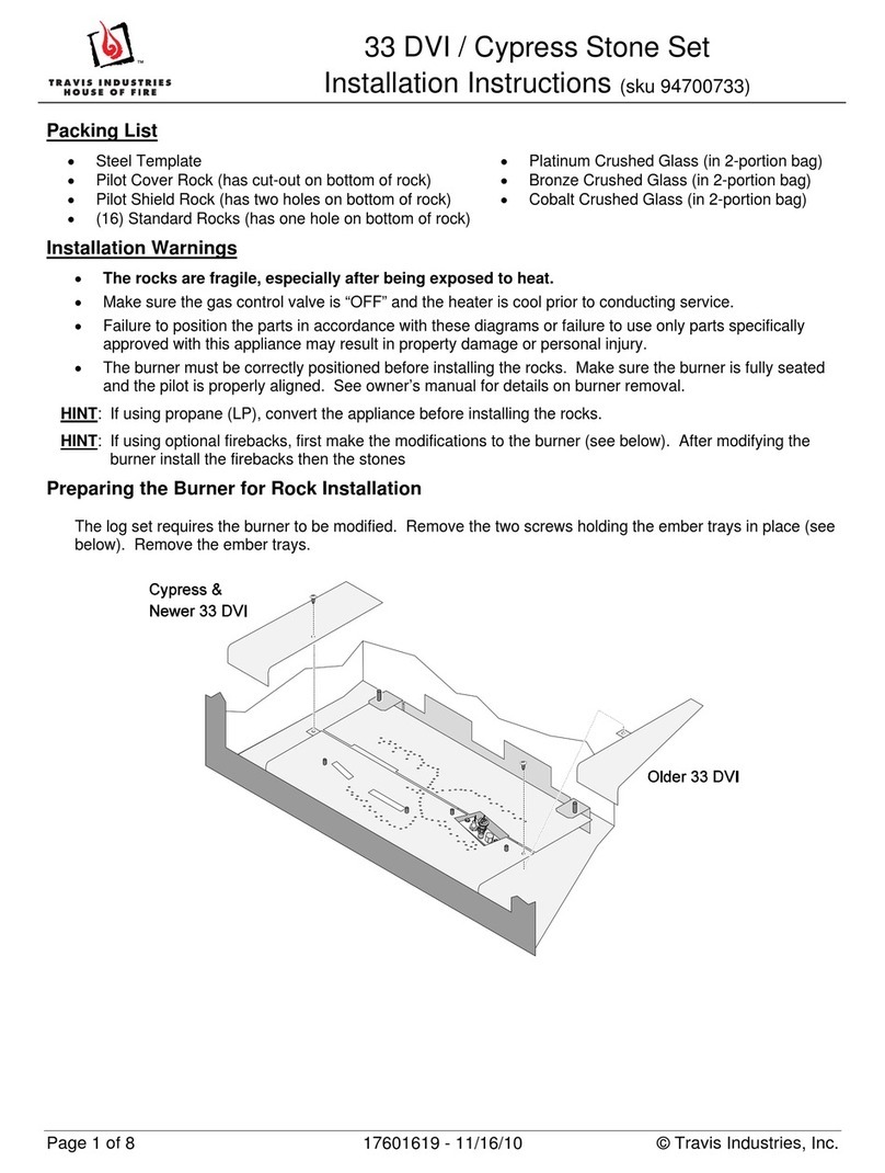
Travis Industries 33 DVI installation instructions
Lopi
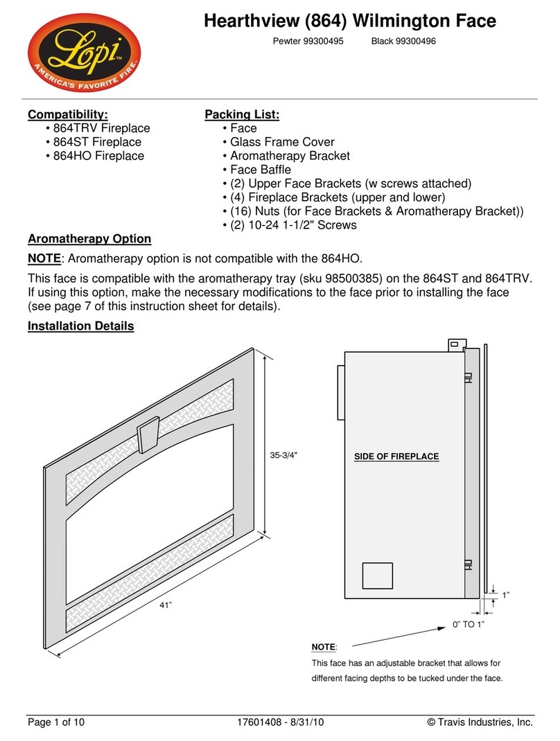
Lopi Hearthview 864 user manual
Lennox Hearth Products
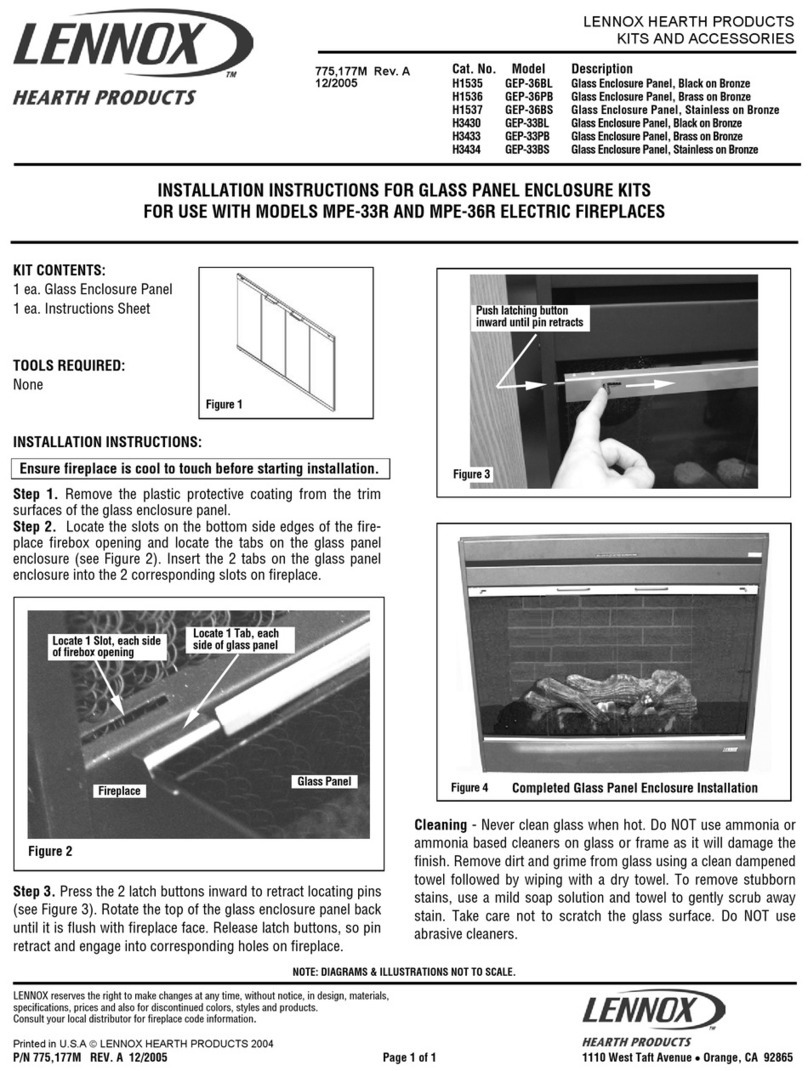
Lennox Hearth Products LENNOX MPE-33R installation instructions
Dimplex
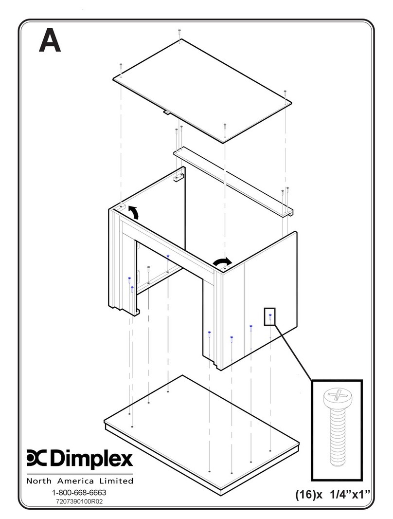
Dimplex DFP6776C install guide
Napoleon
Napoleon W175-0689 instruction manual
Travis Industries
Travis Industries 95400424 installation instructions
Osburn
Osburn ZERO CLEARANCE KIT installation instructions
Majestic
Majestic QUARTZPLA36IN installation instructions
Napoleon
Napoleon DBPO36 installation instructions
Dimplex
Dimplex SMP-130-E install guide
Empire Comfort Systems
Empire Comfort Systems LS50TINF installation instructions
