C&T Solution CT-AIB01 User manual

USER'S MANUAL
Of
Intel Q77 Express Chipset
Based
M/B for LGA 1155 Quad Core Ready
Intel Core Processor
No. G03-NAF93-F
Rev: 1.0
Release date: May 11, 2012
Trademark:
* Specifications and Information contained in this documentation are furnished for information use only, and are
subject to change at any time without notice, and should not be construed as a commitment by manufacturer.

ii
ENVIRONMENTAL SAFETY INSTRUCTION...........................................................................iii
ENVIRONMENTAL PROTECTION ANNOUCEMENT..............................................................iii
USER’S NOTICE .......................................................................................................................iv
MANUAL REVISION INFORMATION.......................................................................................iv
ITEM CHECKLIST.....................................................................................................................iv
CHAPTER 1 INTRODUCTION OF THE MOTHERBOARD
1-1 SPECIFICATION.........................................................................................................1
1-2 LAYOUT DIAGRAM....................................................................................................2
CHAPTER 2 HARDWARE INSTALLATION
2-1 JUMPER SETTING.....................................................................................................5
2-2 CONNECTORS AND HEADERS................................................................................10
2-2-1 REAR I/O BACK PANEL CONNECTORS....................................................10
2-2-2 MOTHERBOARD INTERNAL CONNECTORS............................................11
2-2-3 HEADER PIN DEFINITION ...........................................................................14
CHAPTER 3 INTRODUCING BIOS
3-1 ENTERNING SETUP...................................................................................................20
3-2 BIOS MENU SCREEN ................................................................................................20
3-3 FUNCTION KEYS .......................................................................................................21
3-4 GETTING HELP ..........................................................................................................21
3-5 MENU BARS...............................................................................................................22
3-6 MAIN MENU................................................................................................................22
3-7 ADVANCED MENU.....................................................................................................23
3-8 CHIPSET MENU..........................................................................................................29
3-9 BOOT MENU...............................................................................................................32
3-10 SECURITY MENU.......................................................................................................33
3-11 SAVE & EXIT MENU...................................................................................................34
TABLE OF CONTENT

iii
Environmental Safety Instruction
zAvoid the dusty, humidity and temperature extremes. Do not place the product in
any area where it may become wet.
z0 to 40 centigrade is the suitable temperature. (The figure comes from the request
of the main chipset)
zGenerally speaking, dramatic changes in temperature may lead to contact
malfunction and crackles due to constant thermal expansion and contraction from
the welding spots’ that connect components and PCB. Computer should go
through an adaptive phase before it boots when it is moved from a cold
environment to a warmer one to avoid condensation phenomenon. These water
drops attached on PCB or the surface of the components can bring about
phenomena as minor as computer instability resulted from corrosion and oxidation
from components and PCB or as major as short circuit that can burn the
components. Suggest starting the computer until the temperature goes up.
zThe increasing temperature of the capacitor may decrease the life of computer.
Using the close case may decrease the life of other device because the higher
temperature in the inner of the case.
zAttention to the heat sink when you over-clocking. The higher temperature may
decrease the life of the device and burned the capacitor.
Environmental Protection Announcement
Do not dispose this electronic device into the trash while discarding. To minimize
pollution and ensure environment protection of mother earth, please recycle.

iv
USER’S NOTICE
COPYRIGHT OF THIS MANUAL BELONGS TO THE MANUFACTURER. NO PART OF THIS MANUAL,
INCLUDING THE PRODUCTS AND SOFTWARE DESCRIBED IN IT MAY BE REPRODUCED, TRANSMITTED
OR TRANSLATED INTO ANY LANGUAGE IN ANY FORM OR BY ANY MEANS WITHOUT WRITTEN
PERMISSION OF THE MANUFACTURER.
THIS MANUAL CONTAINS ALL INFORMATION REQUIRED TO USE THIS MOTHER-BOARD SERIES AND WE
DO ASSURE THIS MANUAL MEETS USER’S REQUIREMENT BUT WILL CHANGE, CORRECT ANY TIME
WITHOUT NOTICE. MANUFACTURER PROVIDES THIS MANUAL “AS IS” WITHOUT WARRANTY OF ANY
KIND, AND WILL NOT BE LIABLE FOR ANY INDIRECT, SPECIAL, INCIDENTAL OR CONSEQUENTIAL
DAMAGES (INCLUDING DAMAGES FOR LOSS OF PROFIT, LOSS OF BUSINESS, LOSS OF USE OF DATA,
INTERRUPTION OF BUSINESS AND THE LIKE).
PRODUCTS AND CORPORATE NAMES APPEARING IN THIS MANUAL MAY OR MAY NOT BE
REGISTERED TRADEMARKS OR COPYRIGHTS OF THEIR RESPECTIVE COMPANIES, AND THEY ARE
USED ONLY FOR IDENTIFICATION OR EXPLANATION AND TO THE OWNER’S BENEFIT, WITHOUT
INTENT TO INFRINGE.
Manual Revision Information
Reversion Revision History Date
1.0 First Edition May 11, 2012
Item Checklist
5Motherboard
5User’s Manual
5DVD for motherboard utilities
5Cable(s)
5I/O Back panel shield

1
Chapter 1
Introduction of the Motherboard
1-1 Specification
Spec Description
Design zATX form factor; PCB size: 30.0 x24.4 cm
Chipset zIntel Q77 Express Chipset
LGA1155
CPU Socket
zSupports 3rd and 2nd Generation Intel®Core™ i7, Core™ i5,
Core™ i3 series processor in LAG1155 Package
* for detailed CPU support information please visit our website
Memory Slot
zDDRIII RAM module slot x 4
zSupporting four DDRIII 1600/1333/1066MHz RAM Module
expandable to 32 GB (Maximum)
zSupport dual-channel function
Expansion Slots
z1 pcs* PCI-Express x16 slot
z1 pcs* PCI-Express x4 slot
z1 pcs* PCI-Express x1 slot
z4 pcs *32-bit PCI slot
z1 pcs* Full-size Mini-PCIE slot/MSATA slot
z1 pcs*Half-size Mini-PCIE slot
Storage zSupport four SATAII ports
zSupport two SATAIII ports
Dual LAN Chip
zIntegrated Intel 82574L and 82579LM Gigabit Ethernet LAN chip
that supports Fast Ethernet LAN function of providing
10/100/1000Mbps Ethernet data transfer rate
HD Audio Chip zRealtek ALC662 6-channel Audio Codec integrated
zAudio driver and utility included
BIOS z64MB DIP Flash ROM
Multi I/O
zUSB 3.0 port connector x2
zHDMI port connector x1
zSerial port connector x2
zDVI-D port connector x1/VGA port connector x1
zUSB 2.0 port connector x4
zRJ-45 LAN connector x2
zAudio connector x3 (Line-in, Line-out, MIC)
zFront panel audio header x1
zHDMI-SPDIF header x1
zCDIN header x1
zParallel header x1
zTPM 1.2 header x1
zGPIO header x1
zUSB 2.0 header x2
zUSB 3.0 header x1
zFront panel header x1
zPOWER LED header x1
zSpeaker header x1
zCIR header x1
zLANLED header x2
zSM_BUS header x1
zTX-RX COM header x 1
zCOM port header x 8

2
1-2 Layout Diagram
Rear IO Diagram
Motherboard Internal Diagram
RJ-45 LAN Ports
USB 3.0 Ports Line-IN/
Optical SPDIF OUT
Line-OUT
MIC-IN
USB 2.0 Ports
Serial Port 1
VGA Port
ATX 12V
Power Connector
ATX Powe
r
Connector
LGA1155
CPU Socket
DVI-D Port
HDMI Port Serial Port 2
Audio Connectors
USB 3.0 PortS over
HDMI port
Serial Port s
(COM1 over COM2)
DVI –D Port over
VGA Port
RJ-45 LAN Ports
Over USB 2.0 Ports
RJ-45 LAN Ports
Over USB 2.0 Ports USB 3.0 Header
PCI Express x16 Slot (PE1) *
PCI Express 2.0 x 4 Slot
P
CI E
x
p
ress 2.0 x1 Slo
t
32-bit
P
CI Slo
t
s
Front Panel
Audio Heade
r
CDIN Header
Parallel Header TPM Header
TX-RX COM Heade
r
Intel Q77
Chipset
USB 2.0 Headers
Front Panel Header
DDRIII
DIMM Slot x 4
Full-size Mini-PCIE
/MSATA Slot*
Half-size
Mini-PCIE Slot
E
DP Connector*
SYS FAN2 Header
GPIO Header
SYS FAN1
Header
KBMS Header CPUFAN Header
SM_BUS Header
CIR Header
Serial Ports (COM3/5/7/9)
SATAIII Ports
SATAII Ports
SATAII Ports
Serial Ports (COM4/6/8/10)
HDMI S/PDIF Header
LAN1LED Header
LAN2LED Header
PWR LED Header
Speaker Header

3
*Note:
1.PE1 slot supports PCI-Express 2.0 x16 specification when using Intel®Sandy Bridge CPU and
supports PCI-Express 3.0 x16 specification when using Intel®Ivy Bridge CPU; 2. mSATA slot is
selectable with full size MINI PCI-E and share with SATA6; 3. EDP connector is only optional for customize
model.
Motherboard Jumper Position
Jumper
Jumper Name Description
JBAT CMOS RAM Clear Function Setting 3-pin Block
JP2 Mini PCI-E Power VCC3.3V/3.3VSB Select 3-pin Block
JP3 (Optional) EDP Panel Power 5V/3.3V Select 3-pin Block
JP1 COM1 Ports Pin9 Function Select 6-pin Block
JP4 COM3 Header Pin9 Function Select 6-pin Block
JP5 COM5 Header Pin9 Function Select 6-pin Block
JP6 COM7 Header Pin9 Function Select 6-pin Block
JP7 COM9 Header Pin9 Function Select 6-pin Block
JP2
CASE_OPEN
J
P1
JP3
J
BA
T
JP12
J
P
7
JP
4
JP
5
JP
11
JP
10
JP
9
JP
6
JP
8

4
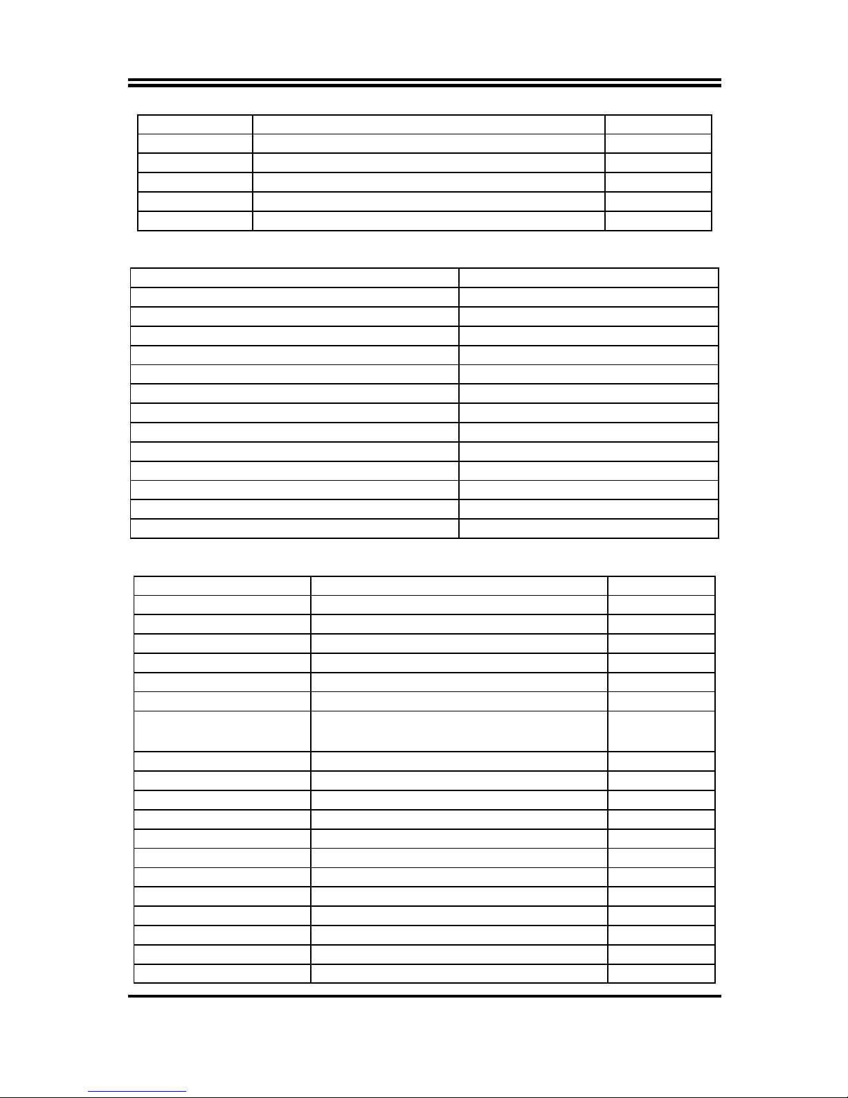
JP8 COM4 Header Pin9 Function Select 6-pin Block
JP9 COM6 Header Pin9 Function Select 6-pin Block
JP10 COM8 Header Pin9 Function Select 6-pin Block
JP11 COM10 Header Pin9 Function Select 6-pin Block
JP12 COM4 Header RS232/485/422 Function Select 6-pin Block
Case_open Case Open Message Display Function Select 2-pin Block
Connectors
Connector Name
ATXPWR ATX Power Connector
ATX12V1 ATX 12V Power Connector
USB4 USB 3.0 Connector X2
HDMI High-Definition Multimedia Interface
VGA Video Graphic Attach Connector
DVI DVI-D Port Connector
COM1(Top)/COM2(Bottom) Serial Port COM Connector X2
UL1(Middle & Bottom)/UL2(Middle & Bottom) USB 2.0 Port Connector X4
UL1(Top)/UL2(Top) RJ-45 LAN Connector X2
AUDIO1 Audio Connector X3
SATA1_2 SATAIII Connector X2
SATA3_4/SATA5/SATA6 SATAII Connectors X4
EDP (Optional) EDP connector
Headers
Header Name Description
FP_AUDIO Front panel audio Header 10-pin block
CDIN1 CD Audio-In Header 4-pin Block
HDMI_SPDIF HDMI_SPDIF Out Header 2-pin Block
KBMS PS/2 Keyboard & Mouse Header 6-pin Block
SPEAK Speaker Header 4-pin Block
PWRLED Power LED 3-pin Block
JW_FP
(Front Panel Header) PWR LED/ HD LED/ /Power Button
/Reset 10-pin Block
CIR CIR Header 8-pin Block
USB1 USB 3.0 Header 20-pin Block
USB2/USB3 USB 2.0 Header 10-pin Block
COM 3/4/5/6/7/8/9/10 Serial Port Header 10-pin Block
TX-RXCOM RS 422/485 port headers 4-pin block
GPIO_CON GPIO Header 10-pin Block
TPM TPM Header 20-pin Block
PARALLEL Parallel Port Header 26-pin Block
LAN1LED/LAN2LED LANLED 2-pin Block
SM_BUS SMBUS Header 4-pin Block
SYSFAN1 SYSFAN1 Header 3-pin Block
SYSFAN2/CPUFAN1 FAN Header 4-pin Block

5
Chapter 2
Hardware Installation
2-1 Jumper Setting
(1) JBAT (3-pin): Clear CMOS
2-3 Short:Clear CMOS
JBAT JBAT
1-2 closed : Normal
;
1
3
CMOS Clear Setting
(2)JP2 (3-pin): Mini PCI-E Power VCC 3.3V/3.3 VSB Select
2-3 closed :MINI PCI-E VCC= 3.3VSB
JP2
JP2
1-2 closed :MINI PCI-E VCC= 3.3V;
1
3
13
(3)JP3 (3-pin): EDP Panel Power 5V/3.3 V Select
2-3 closed :EDP Panel Power=3.3V;
JP3
JP3
1-2 closed :EDP Panel Power=5V;
1
3
13

6
*Note:
JP3 is optional for customize model with EDP connector.
(4) JP1 (6-pin): COM1 Port Pin9 Function Select
3-4 closed : +12V;
JP1
1-2 closed: RS232;
1
5-6 closed : +5V
11
(5) JP4 (6-pin): COM3 Port Pin9 Function Select
3-4 closed : +12V;
JP4
1-2 closed: RS232;
1
5-6 closed : +5V
11
(6) JP5(6-pin): COM5 Port Pin9 Function Select
3-4 closed : +12V;
JP5
1-2 closed: RS232;
1
5-6 closed : +5V
11

7
(7) JP6(6-pin): COM7 Port Pin9 Function Select
3-4 closed : +12V;
JP6
1-2 closed: RS232;
1
5-6 closed : +5V
11
(8) JP7(6-pin): COM9 Port Pin9 Function Select
3-4 closed : +12V;
JP7
1-2 closed: RS232;
1
5-6 closed : +5V
11
(9) JP8(6-pin): COM4 Port Pin9 Function Select
3-4 closed : +12V;
JP8
1-2 closed: RS232;
1
5-6 closed : +5V
11

8
(10) JP9(6-pin): COM6 Port Pin9 Function Select
3-4 closed : +12V;
JP9
1-2 closed: RS232;
1
5-6 closed : +5V
11
(11) JP10(6-pin): COM8 Port Pin9 Function Select
3-4 closed : +12V;
JP10
1-2 closed: RS232;
1
5-6 closed : +5V
11
(12) JP11(6-pin): COM10 Port Pin9 Function Select
3-4 closed : +12V;
JP11
1-2 closed: RS232;
1
5-6 closed : +5V
11

9
(13) JP12 (6-pin): COM4 Header RS232/485/422 Function Select
3-4 closed : RS485;
JP12
1-2 closed: RS232;
1
5-6 closed : RS422
11
(14) CASE_ OPEN (2-pin): Case Open Message Display Function Select
Pin 1-2 shorted: Case open display function enabled. Use needs to enter BIOS and
enable ‘Case Open Detect’function. In this case if you case is removed, next time
when you restart your computer a message will be displayed onscreen to inform you
of this.

10
2-2 Connectors and Headers
2-2-1 Rear I/O Back Panel Connectors
(1) USB 3.0 Port Connector: USB4
These USB 3.0 connectors are for user to connect USB 3.0 compatible devices
to the system board.
(2) D-Sub 15-pin Connector: VGA
VGA connector is the 15-pin D-subminiature female connector; it is for the
display devices, such as the CRT monitor, LCD monitor and so on.
(3) Digital Visual Interface: DVI
This interface standard designed to maximize the visual quality of digital display
devices such as flat panel LCD computer displays and digital projectors.
(4) High-Definition Multimedia Interface: HDMI
This point-to-point interface is for audio and video signals designed as a
single-cable solution for home theater and consumer electronics equipment.
NOTE! DVI and HDMI Connector can not be used at the same time.
(5) USB 2.0 Port Connector: UL1(Middle & Bottom)/ UL2(Middle & Bottom)
The connectors are 4-pin connector that connects USB devices to the system
board.
(6) RJ-45 LAN Port Connectors: UL1(Top)/UL2(Top)
The connectors are standard RJ-45 connectors for Network.
(7) Serial Port Connector: COM1 (Top)/COM2(bottom)
These two serial ports are for user to connect compatible mouse, modern or
other peripherals.
(8) Audio Line-In, Lin-Out connector: AUDIO1
These Connectors are 3 Phone-Jack for LINE-OUT, LINE-IN, MIC audio
connections.
Line-in: (BLUE) Audio input to sound chip
Line-out: (GREEN) Audio output to speaker
MIC: (PINK) Microphone Connector
RJ-45 LAN Ports
USB 3.0 Ports Line-IN/
Optical SPDIF OUT
Line-OUT
MIC-IN
USB 2.0 Ports
Serial Port 1
VGA Port
DVI-D Port
HDMI Port Serial Port 2

11
2-2-2 Motherboard Internal Connectors
(1) Power Connector (24-pin block): ATXPWR
ATX Power Supply connector: This is a new defined 24-pins connector that
usually comes with ATX case. The ATX Power Supply allows using soft power
on momentary switch that connect from the front panel switch to 2-pins Power
On jumper pole on the motherboard. When the power switch on the back of the
ATX power supply turned on, the full power will not come into the system board
until the front panel switch is momentarily pressed. Press this switch again will
turn off the power to the system board.
** We recommend that you use an ATX 12V Specification 2.0-compliant power
supply unit (PSU) with a minimum of 350W power rating. This type has 24-pin
and 4-pin power plugs.
** If you intend to use a PSU with 20-pin and 4-pin power plugs, make sure that the
20-pin power plug can provide at least 15A on +12V and the power supply unit
has a minimum power rating of 350W. The system may become unstable or may
not boot up if the power is inadequate.
** If you are using a 20-pin power plug, please refer to Figure1 for power supply
connection. Power plug form power supply and power connectors from
motherboard both adopt key design to avoid mistake installation. You can insert
the power plug into the connector with ease only in the right direction. If the
direction is wrong it is hard to fit in and if you make the connection by force if is
possible.
Figure1:20-pinpowerplug Figure2:24-pin power plug

12
(2) ATX 12V Power Connector (8-pin block): ATX12V
This is a new defined 8-pin connector that usually comes with ATX Power
Supply. The ATX Power Supply which fully supports AMD AM3 processor must
including this connector for support extra 12V voltage to maintain system power
consumption. Without this connector might cause system unstable because the
power supply can not provide sufficient current for system.
Pin1 4
Pin Definition No. Definition
1 GND 5 +12V
2 GND 6 +12V
3 GND 7 +12V
4 GND 8 +12V
(3) SATAIII Port connector: SATA1_2
These connectors are high-speed SATAIII ports that support 6 GB/s transfer rate.
Pin No. Defnition
1 GND
2 TXP
3 TXN
4 GND
5 RXN
6 RXP
7 GND
(4) SATAII Port connector: SATA3_4; SATA5; SATA6
These connectors are high-speed SATAII ports that support 3 GB/s transfer rate.
Pin No. Defnition
1 GND
2 TXP
3 TXN
4 GND
5 RXN
6 RXP
7 GND

13
(5) EDP(40-pin): EDP Connector
Pin NO. Pin Define Pin NO. Pin Define
Pin 1 NC Pin 21 LCD_GND
Pin 2 GND Pin 22 LCD_GND
Pin 3 EDP_DATA3N Pin 23 EDP_HPD
Pin 4 EDP_DATA3P Pin 24 GND
Pin 5 GND Pin 25 GND
Pin 6 EDP_DATA2N Pin 26 GND
Pin 7 EDP_DATA2P Pin 27 GND
Pin 8 GND Pin 28 EDP_BKLT_EN
Pin 9 EDP_DATA1N Pin 29 EDP_BKLT_PWM
Pin 10 EDP_DATA1P Pin 30 NC
Pin 11 GND Pin 31 NC
Pin 12 EDP_DATA0N Pin 32 BKLT_PWR
Pin 13 EDP_DATA0P Pin 33 BKLT_PWR
Pin 14 GND Pin 34 BKLT_PWR
Pin 15 EDP_AUXP Pin 35 BKLT_PWR
Pin 16 EDP_AUXN Pin 36 NC
Pin 17 GND Pin 37 NC
Pin 18 LCD_VCC Pin 38 NC
Pin 19 LCD_VCC Pin 39 NC
Pin 20 NC Pin 40 NC
*Note:
EDP connector is only optional for customized model.

14
2-2-3 Header Pin Definition
(1) FP_AUDIO (10-pin): Line-Out, MIC-In Header
This header is connected to Front Panel Line-out, MIC connector with cable.
Line-Out, MIC Header
FP_AUDIO
Pin1
MIC1-R
LINE OUT-L
MIC1-L
LINE OUT-R
NC
GND
NC
NC
NC
2
(2) CDIN1(4-pin): CD AUDIO-In Header
CDIN header is for CD-Audio Input signal. Please connect it to CD-ROM
CD-Audio output connector.
Pin1
GND
CD-R
CD-L
GND
(3) HDMI_SPDIF(2-pin): HDMI-SPDIF Out header
HDMI_SPDIF Header
Pin1
SPDIF
GND

15
(4) KBMS (6-pin): PS/2 Keyboard & Mouse Header
GND
KB CLK
KB
_
DATA
Pin1
MS
_
DATA
VCC
MS CLK
(5) SPEAK (4-pin): Speaker Header
This 4-pin header connects to the case-mounted speaker. See the figure below.
(6) PWR LED(3-pin): PWR LED Header
The Power LED is light on while the system power is on. Connect the Power LED
from the system case to this pin header.
SPEAK
SPEAK
NC
NC
VCC
Pin 1
PWRLED
Pin 1
VCC
GND
GND
(7) JW-FP(10-pin): Front Panel Header
HDLED
RESET
HDDLED+
GND
PWRLED+
PWRBTN GND
PWRLED- HDDLED-
RSTSW
V
CC
PWRBT
Pin 1
2
PWR LED

16
(8) CIR (8-Pin): CIR Header
CIR Header
GND
NC
ATX 5VSB
CIR LED
V
CC
CIR _WB
2
Pin 1
CIR RX
(9) USB 3.0 Port Header (20-pin): USB1
This USB 3.0 header is used for connecting the additional USB 3.0 port plugs. By
attaching an optional USB 3.0 cable, your can be provided with two additional
USB 30 plugs affixed to the back panel.
SSRX2-
SSRX2+
GND2
SSTX2-
SSTX2+
GND3
D2-
D1+
VBUS
11
Pin1 10
20
VBUS
SSRX1-
SSRX1+
GND0
SSTX1-
SSTX1+
GND1
D1-
D1+
NC
(10) USB 2.0 Port Headers (10-pin): USB2/USB3
These headers are used for connecting the additional USB 2.0 port plugs. By
attaching an option USB cable, your can be provided with two additional USB 2.0
plugs affixed to the back panel.
Pin 1
V
CC
-DATA
GND
+DATA
V
CC
NC
-DATA
GND
+DATA
Table of contents
Other C&T Solution Motherboard manuals

C&T Solution
C&T Solution CT-MSB01 User manual

C&T Solution
C&T Solution G03-NF9G- User manual

C&T Solution
C&T Solution CT-MHW0X User manual

C&T Solution
C&T Solution CT-XHW0X User manual

C&T Solution
C&T Solution CT-PBT01 Series User manual

C&T Solution
C&T Solution CT-XBT0x User manual

C&T Solution
C&T Solution CT-DWL01 User manual

C&T Solution
C&T Solution CT-DBX0x User manual

C&T Solution
C&T Solution CT-DBT0x User manual

C&T Solution
C&T Solution CT-CCV6X User manual