C&T Solution CT-PBT01 Series User manual

USER’S
MANUAL
CT-PBT01 Series
PICO-ITX SBC

CT-PBT01 | User’s Manual
Table of Contents
Safety Information ………….……………………….……………………………………………. 03
About This Guide ……….…………………………….……………………………..……………. 04
Packing List ……………….…………………………….……………………………………………. 05
Ordering Information …………………………………………………………………………….. 05
Revision History ….…….…………………………….……………………………………………. 05
Chapter 1 Product Introductions ……………………………………………………...… 06
1.1 Hardware Specification …………………………………..………….………..……..….…….. 07
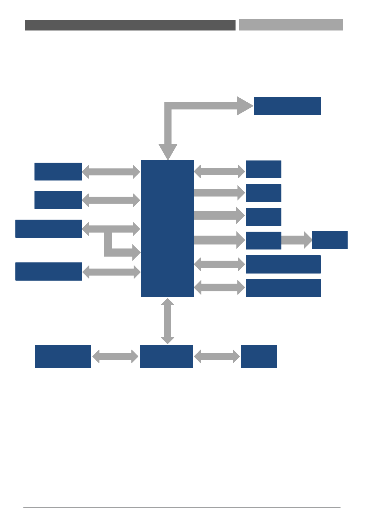
1.2 Block Diagram ….…………………………………….…......………….………....…...………… 08
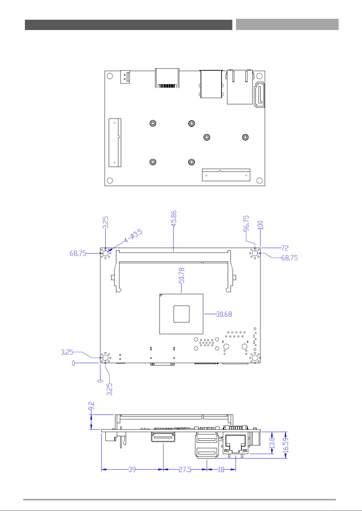
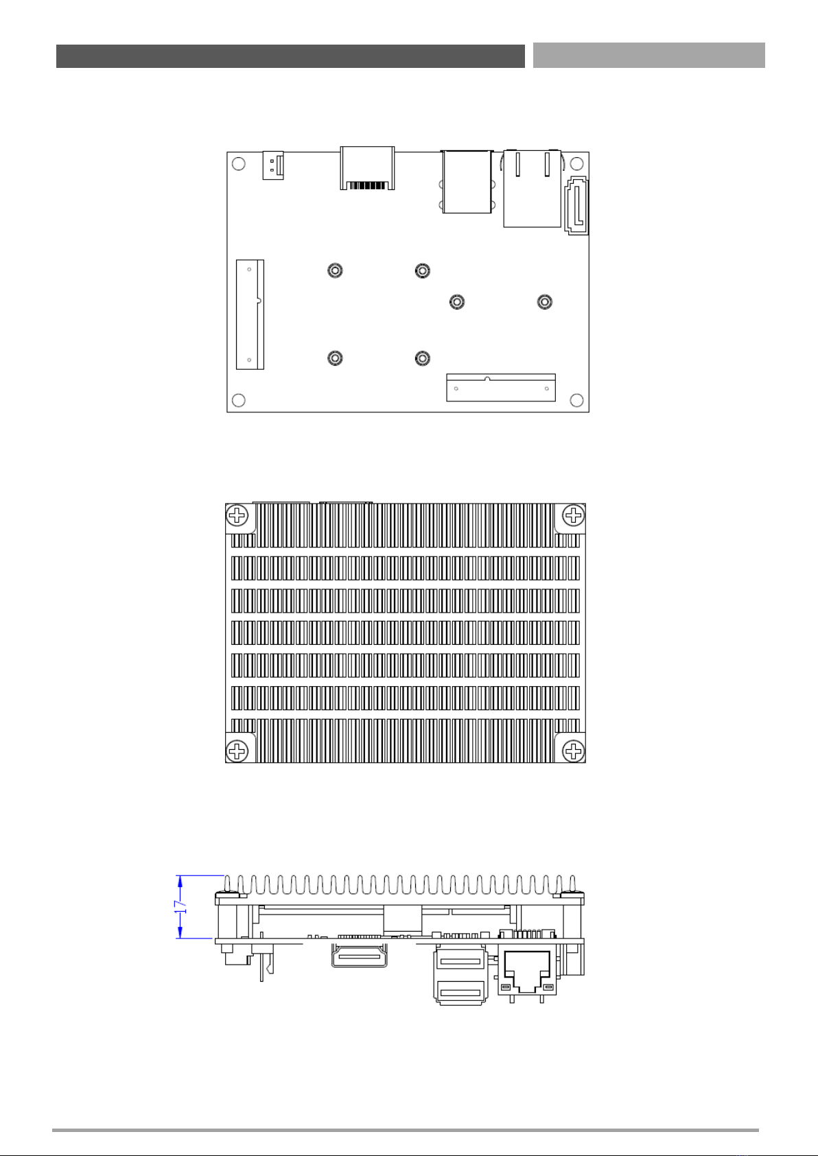
1.3 Board Dimensions ………………………………..……..………………………….………..…… 09
1.4 Connectors …………………………………..…………………………..………..…………………. 11
1.4.1 Connectors Definition ……………….………..…………….…………..…..………… 12
Chapter 2 BIOS Setup ………………….…………………………………………………...… 20
2.1 BIOS Setup ………………………………………………….…..………….………..……..….…….. 21
2.2 Entering Setup …………………………………………….…..………….………..……..….……. 22
2.2.1 Main Setup ………………………………………..………………………………………………… 22
2.2.2 Advanced BIOS Features Setup ………………..………………………………………….. 23
2.2.2.1 ACPI Settings Configuration ……………………………….……………….……..…… 24
2.2.2.2 Super I/O Monitor ………………………………………………………………………….. 25
2.2.2.3 H/W Monitor ………………………………………………………………………………….. 26
2.2.2.4 Serial Port Console Redirection ………………………………………………………. 27
2.2.2.5 CPU Configuration ………………………………………………………………………….. 28
2.2.2.6 SATA Configuration …………………………………………………………................. 29
2.2.2.7 OS Selection …………………………………………………………………………………… 30
2.2.2.8 Network Stack Configuration …………………………………………………………. 31
2.2.2.9 CSM Configuration …………………………………………………………………….….. 32
2.2.2.10 USB Configuration ……………………………………………………………………….. 33
2.2.2.11 Intel I210 Gigabit Network Connection ……………………………………….. 34
2.2.3 Chipset Configuration ……...........................…..………………………………..…… 35
2.2.3.1 North Bridge ……………………………………………………………………...…………. 36
2.2.3.2 Intel IGD Configuration ……………………………………………………….…………. 37
2.2.3.3 South Bridge …………………………………………………………………..…………….. 38
2.2.3.4 Azalia HD Audio …………………………………………………………………………….. 39
2.2.3.5 USB Configuration …………………………………………………………………………. 40
2.2.3.6 PCI Express Configuration ……………………………………………………………... 41
2.2.4 Security …………………………………..…………………..………………………………..…… 42
2.2.5 Boot ……………………………………………………………………..…………..…………..…… 43
2.2.6 Save & Exit ………………………………………………………………………………………..... 44
Appendix WDT & GPIO ……………………..………………………………………..……...… 45
Watchdog Timer …………………………………..………….………..……..………………………….............….. 46
GPIO ………………………………………………..…..………….………..……..………………………….............….. 47
2

CT-PBT01 | User’s Manual
3
Safety Information
Electrical Safety
To prevent electrical shock hazard, disconnect the power cable from the electrical outlet before
relocating the system.
When adding or removing devices to or from the system, ensure that the power cables for the
devices are unplugged before the signal cables are connected. If possible, disconnect all power cables
from the existing system before you add a device.
Before connecting or removing signal cables from the motherboard, ensure that all power cables are
unplugged.
Seek professional assistance before using an adapter or extension cord. These devices could interrupt
the grounding circuit.
Make sure that your power supply is set to the correct voltage in your area. If you are not sure about
the voltage of the electrical outlet you are using, contact your local power company.
If the power supply is broken, do not try to fix it by yourself. Contact a qualified service technician or
your retailer.
Operation Safety
Before installing the motherboard and adding devices on it, carefully read all the manuals that came
with the package.
Before using the product, make sure all cables are correctly connected and the power cables are not
damaged. If you detect any damage, contact your dealer immediately.
To avoid short circuits, keep paper clips, screws, and staples away from connectors, slots, sockets and
circuitry.
Avoid dust, humidity, and temperature extremes. Do not place the product in any area where it may
become wet.
Place the product on a stable surface.
If you encounter technical problems with the product, contact a qualified service technician or your
retailer.
Safety Declaration
This device complies with the requirements in Part 15 of the FCC rules. Operation is subject to the
following two conditions:
This device may not cause harmful interference.
This device must accept any interference received, including interference that may cause undesired
operation.
Preface
The symbol of the crossed out wheeled bin indicates that the
product (electrical and electronic equipment) should not be placed
in municipal waste. Check local regulations for disposal of
electronic products.

CT-PBT01 | User’s Manual
4
Preface
About this guide
This user guide contains the information you need when installing and configuring the motherboard.
How this guide is organized
This manual contains the following parts:
Chapter 1: Product introduction
This chapter describes the features of the motherboard and the new technology it supports. This
chapter also lists the hardware setup procedures that you have to perform when installing system
components. It includes description of the jumpers and connectors on the motherboard.
Chapter 2: BIOS setup
This chapter tells how to change system settings through the BIOS Setup menus. Detailed
descriptions of the BIOS parameters are also provided.
Where to find more information
Refer to the following sources for additional information and for product and software updates.
1. Technical Support
If a problem arises with your system and no solution can be obtained from the user’s manual, please
contact your place of purchase or local distributor.
2. Optional documentation
Your product package may include optional documentation, such as warranty flyers, that may have
been added by your dealer. These documents are not part of the standard package.
Conventions used in this guide
To make sure that you perform certain tasks properly, take note of the following symbols used
throughout this manual.
This indication alerts operators to an operation that, if not strictly observed,
may result in severe injury.
WARNING
This indication alerts operators to an operation that, if not strictly observed,
may result in safety hazards to personnel or damage to equipment.
CAUTION
This indication provides additional information to complete a task easily.
NOTE

CT-PBT01 | User’s Manual
5
Preface
Packing List
Before you begin installing your single board, please make sure that the following materials have been
shipped:
If any of the above items is damaged or missing, please contact your retailer.
Revision
Revision History
Date
V 1.0
First
release version
July,
2019
Revision History
Item
Description
Q’ty
1
CT
-PBT01 PICO-ITX SBC 1
2
Heat Sink
1
3
Audio Cable 20cm
1
4
COM Cable 2*10P
-2*DB9 22cm 1
5
Power Cable
10cm 1
6
SATA Cable
30cm 1
7
SATA Power Cable
1
8
USB
Cable 1
9
Copper Stud and Screws for Heat
Sink 4
10
Screws for
Mini PCIe Card 2
Ordering Information
Model No. Product Description
CT-PBT01 Pico-ITX SBC with Intel Celeron J1900, HDMI, 1x LAN, 4x USB, 2x COM
CT-PBT02 Pico-ITX SBC with Intel Celeron J1900, VGA, 1x LAN, 4x USB, 2x COM

Chapter 1
Product Introductions

CT-PBT01 | User’s Manual
7
1.1 Hardware Specification
System
•CPU: Intel® Celeron® Processor J1900
(2.0GHz/4C/10W)
•System Chipset: SoC integrated
•LAN Chipset: 1x Intel® I210AT GbE controller
•Audio Codec: Realtek ALC888S
•Memory: 1x 204-Pin DDR3L 1066/1333MHz
SODIMM
•Max Size: 8GB
•BIOS: AMI 64Mbit SPI BIOS
•Watchdog Timer: Software Programmable Supports
1~255 sec. System Reset
Display
•Chipset: Intel® SoC Integrated
•Interface:
- 1x HDMI (2048x1080 @60Hz)
- 1x LVDS (single channel, 18bit/24bit)
•Multiple Display: Dual Display
Storage
•SATA: 1x SATA 3.0Gb/s
•mSATA: 1x mSATA (shared by 1x Mini PCIe)
Expansion
•Mini PCI Express:
- 1x Half-size Mini PCIe
- 1x Half-size Mini PCIe (Full-size as BOM option)
Rear I/O
•Display: 1x HDMI (1x VGA as BOM option)
•USB: 1x USB 3.0, 1x USB 2.0
•LAN: 1x RJ45
Internal I/O
•Display:
- 1x LVDS
- 1x LVDS backlight
•COM: 1x RS-232/422/485, 1x RS-232
•USB: 2x USB 2.0
•SATA: 1x SATA 3.0Gb/s
•Audio: 1x Front panel audio
•GPIO: 1x 8-bit GPIO (4-in/4-out)
•Others:
- 1x Front panel
- 1x SMBus
Operating System
•Windows: Windows 10, Windows 7, WES7
•Linux: Linux Kernel 3.x
Power
•Power Connector: 2-pin power connector
•Power Input: 12V DC Input
•Management: ACPI
Mechanical & Environment
•Form Factor: PICO-ITX
•Dimension: 100mm x 72mm
•Operating Temp.: -10°C ~ 70°C
•Storage Temp.: -40°C ~ 85°C
•Operating Humidity: 10% ~ 90% relative humidity,
non-condensing
Chapter 1: Product Introductions

CT-PBT01 | User’s Manual
8
1.2 Block Diagram
HD-Audio
PCI-Express x1
SATA Port 1
PCI-Express x1
SIO SCH3114 RS232
(COM2)
RS232/422/485
(COM1)
Mini-PCIE
Mini-PCIE / mSATA
AUDIO ALC888S
Dual Channel DDRIII 1066/1333 MHz
SATA Port 0
USB2.0/3.0
USB2.0
RGB
DDI0 LVDS 18bit
LVDS
SATA
HDMI
USB3.0 + USB2.0 Ports
Internal USB2.0 Ports
VGA
CH7511B
DDI0
PCI-Express x1
GIGA LAN
I120AT
Bay Trail-D
DDR3L SODIMM
Serial Port Serial Port
LPC BUS
Chapter 1: Product Introductions

CT-PBT01 | User’s Manual
9
1.3 Board Dimensions
Chapter 1: Product Introductions
Unit: mm
Board dimension layout (Top side)
Board dimension layout (Bottom side)
Board dimension layout (coastline)

CT-PBT01 | User’s Manual
10
Chapter 1: Product Introductions
Unit: mm
Board dimension layout (Top side)
Board dimension layout (Bottom side)
Board dimension layout (coastline with heatsink)

CT-PBT01 | User’s Manual
11
1.4 Connectors
Chapter 1: Product Introductions
Top View
Bottom View
(CN15)
mSATA
(CN9)
GPIO
(CN18)
USB2.0
(CN33)
SMBUS
(CN30)
SATA/IVN PWR
(CN16)
mPCIe
(J1)
m-Jump
(BH1)
CMOS
Battery
(CN1)
PWR-IN
HDMI
(CN19)
USB2.0/3.0
(CN24)
LAN
(CN20)
COM
(CN27)
LIN/MIC
(CN13)
PWR SW
(CN14)
SATA
(CN20)
COM
(CN27)
LIN/MIC
(CN13)
PWR SW
(CN31)
LVDS
(CN6)
DIMM

CT-PBT01 | User’s Manual
12
Chapter 1: Product Introductions
Pin Definition
112V
2 GND
Pin Definition Pin Definition
1 VGA_RED 9 VCC5_DVI1
2 VGA_GREEN 10 GND
3 VGA_BLUE 11 NC.
4 NC. 12 VGA_SDA
5 GND 13 VGA_HSYNC
6 GND 14 VSYNC
7 GND 15 VGA_SCL
8 GND
PWR_IN 【CN1】
VGA 【CN11】
USB2.0/3.0 【CN19】
Pin Definition Pin Definition
1 +5V 10 +5V
2D1-11 D2-
3 D1+ 12 D2+
4 GND 13 GND
5 USB_SSRX- H1 CND_E
6 USB_SSRX+ H2 CND_E
7 GND H3 CND_E
8 USB_SSTX- H4 CND_E
9 USB_SSTX+

CT-PBT01 | User’s Manual
13
Chapter 1: Product Introductions
Pin Definition
R1 LAN1+
R2 LAN1-
R3 LAN2+
R4 LAN2-
R5 1.5V
R6 1.5V
R7 LAN3+
R8 LAN3-
R9 LAN4+
R10 LAN4-
L1 LANLED1
L2 PULL-H
L3 LANLED2
L4 LANLED3
LAN 【CN24】
SATA 【CN14】
Pin Definition
1 GND
2 SATA_TX+
3 SATA_TX-
4 GND
5 SATA_RX-
6 SATA_RX+
7 GND

CT-PBT01 | User’s Manual
14
Chapter 1: Product Introductions
mSATA 【CN15】
Pin
Definition
Pin
Definition
Pin
Definition
1 WAKE# 19 Reserved 37 Reserved
2 +3.3V 20 Reserved 38 USB_D2+
3 Reserved 21 GND 39 Reserved
4 GND 22 PERST# 40 GND
5 Reserved 23 MSATA_RXN0 41 Reserved
6 +1.5V 24 +3.3Vaux 42 Reserved
7 CLKREQ#3 25 MSATA_RXP0 43 Reserved
8 Reserved 27 GND 44 Reserved
9 GND 27 GND 45 Reserved
10 Reserved 28 +1.5V 46 Reserved
11 REFCLK2- 29 GND 47 Reserved
12 Reserved 30 SMB_CLK 48 +1.5V
13 REFCLK2+ 31 MSATA_TXN0 49 Reserved
14 Reserved 32 SMB_DATA 50 GND
15 GND 33 MSATA_TXP0 51 Reserved
16 Reserved 34 GND 52 +3.3V
17 Reserved 35 GND 53 GND
18 GND 36 USB_D2- 54 GND
GPIO 【CN9】
Pin Definition Pin Definition
1 +5V_SB 6 GPIO6
2 GPIO4 7 GPIO2
3 GPIO0 8 GPIO7
4 GPIO5 9 GPIO3
5 GPIO1 10 GND

CT-PBT01 | User’s Manual
15
Chapter 1: Product Introductions
Pin Definition Pin Definition
1 +5V_SB 6 USB3-
2 +5V_SB 7 GND
3 USB2+ 8 GND
4 USB3+ 9 GND
5 USB2-
USB2.0 【CN18】
SMBUS 【CN33】
Pin Definition
1 GND
2 SMBDATA
3 SMBCLK
4 +3.3V
SATA/INV PWR 【CN30】
Pin Definition
1 +12V_LED
2 GND
3 INV_ON
4 L_BKLT_CTRL
5 VCCM5

CT-PBT01 | User’s Manual
16
Chapter 1: Product Introductions
mPCIe 【CN16】
Pin
Definition
Pin
Definition
Pin
Definition
1 WAKE# 19 Reserved 37 Reserved
2 +3.3V 20 Reserved 38 USB_D+
3 Reserved 21 GND 39 Reserved
4 GND 22 PERST# 40 GND
5 Reserved 23 PERn0 41 Reserved
6 +1.5V 24 +3.3Vaux 42
LED_WWAN#
7 CLKREQ# 25 PERp0 43 Reserved
8 UIM_PWR 27 GND 44 LED_WLAN#
9 GND 27 GND 45 Reserved
10 UIM_DATA 28 +1.5V 46 LED_WPAN#
11 REFCLK- 29 GND 47 Reserved
12 UIM_CLK 30 SMB_CLK 48 +1.5V
13 REFCLK+ 31 PETn0 49 Reserved
14 UIM_RESET 32 SMB_DATA 50 GND
15 GND 33 PETp0 51 Reserved
16 UIM_VPP 34 GND 52 +3.3V
17 Reserved 35 GND 53 GND
18 GND 36 USB_D- 54 GND
INV PWR by Mini Jump 【J1】
Pin Definition Pin Definition
15V 4 VCCM
2 VCCM 5 SIO_PSIN
3 3.3V 6 3.3V_SB

CT-PBT01 | User’s Manual
17
Chapter 1: Product Introductions
LVDS 【CN31】
Pin Definition Pin Definition
1 GND 8 LVDS_D2+
2 GND 9 LVDS_D1-
3 LVDS_CLK- 10 LVDS_D1+
4 LVDS_CLK+ 11 LVDS_D0-
5 LVDS_D3- 12 LVDS_D0+
6 LVDS_D3+ 13 VCCM
7 LVDS_D2- 14 VCCM
COM1/COM2 【CN20】
Pin Definition Pin Definition
1 DCD1 11 DCD2
2 DSR1 12 DSR2
3 RXD1 13 RXD2
4 RTS1 14 RTS2
5 TXD1 15 TXD2
6 CTS1 16 CTS2
7 DTR1 17 DTR2
8 RI1 18 RI2
9 GND 19 GND
10 GND 20 GND
LINE/MIC【CN27】
Pin Definition Pin Definition
1 LINE_OUT_R 6 LINE_IN_L
2 LINE_IN_R 7 GND
3 GND 8 GND
4 GND 9 MIC_R
5 LINE_OUT_L 10 MIC_L
PWR SW【CN13】
Pin Definition Pin Definition
1 SIO_PSIN 4 PULL-H
2 PULL-H 5 RESET
3 GND 6 SATA_LED

CT-PBT01 | User’s Manual
18
Chapter 1: Product Introductions
DIMM 【CN6】
Pin Definition Pin Definition Pin
Definition
Pin Definition
1 V REFDQ 52 DQ23
103
CK0#
154
DQS5
2 VSS 53 DQ19
104
CK1#
155
VSS
3 VSS 54 VSS
105
VDD
156
VSS
4 DQ4 55 VSS
106
VDD
157
DQ42
5 DQ0 56 DQ28
107
A10/AP
158
DQ46
6 DQ5 57 DQ24
108
BA1
159
DQ43
7 DQ1 58 DQ29
109
BA0
160
DQ47
8VSS 59 DQ25
110
RAS#
161
VSS
9VSS 60 VSS
111
VDD
162
VSS
10 DQS 61 VSS
112
VDD
163
DQ48
11 DM0 62 DQS3
113
WE#
164
DQ52
12 DQS0 63 DM3
114
S0#
165
DQ49
13 VSS 64 DQS3
115
CAS#
166
DQ53
14 VSS 65 VSS
116
ODT0
167
VSS
15 DQ2 66 VSS
117
VDD
168
VSS
16 DQ6 67 DQ27
118
VDD
169
DQS6#
17 DQ3 68 DQ30
119
A13/NC
170
DM6
18 DQ7 69 DQ27
120
ODT1
171
DQS6
19 VSS 70 DQ31
121
S1#
172
VSS
20 VSS 71 VSS
122
NC
173
VSS
21 DQ8 72 VSS
123
VDD
174
DQ54
22 DQ12 73 CKE0
124
VDD
175
DQ50
23 DQ9 74 CKE1
125
NC
176
DQ55
24 DQ13 75 VDD
127
V REFCA
177
DQ51
25 VSS 76 VDD
127
VSS
178
VSS
27 VSS 77 NC
128
VSS
179
VSS
27 DQS1# 78 NC
129
DQ32
180
DQ60
28 DM1 79 BA2
130
DQ36
181
DQ56
29 DQS1 80 NC
131
DQ33
182
DQ61
30 RESET# 81 VDD
132
DQ37
183
DQ57
31 VSS 82 VDD
133
VSS
184
VSS
32 VSS 83 A12/BC#
134
VSS
185
VSS
33 DQ10 84 A11
135
DQS4#
186
DQS7#
34 DQ14 85 A9
136
DM4
187
DM7
35 DQ11 86 A7
137
DQS4
188
DQS7
36 DQ15 87 VDD
138
VSS
189
VSS
37 VSS 88 VDD
139
VSS
190
VSS
38 VSS 89 A8
140
DQ38
191
DQ58
39 DQ16 90 A6
141
DQ34
192
DQ62
40 DQ20 91 A5
142
DQ39
193
DQ59
41 DQ17 92 A4
143
DQ35
194
DQ63
42 DQ21 93 VDD
144
VSS
195
VSS
43 VSS 94 VDD
145
VSS
196
VSS
44 VSS 95 A3
146
DQ44
197
SA0
45 DQS2# 96 A2
147
DQ40
198
EVENT#
46 DM2 97 A1
148
DQ45
199
VDDSPD
47 DQS2 98 A0
149
DQ41
200
SDA
48 VSS 99 VDD
150
VSS
201
SA1
49 VSS
100
VDD
151
VSS
202
SCL
50 DQ22
101
CK1
152
DQS5#
203
Vtt
51 DQ18
102
CK1#
153
DM5
204
Vtt

Chapter 2
BIOS Setup

CT-PBT01 | User’s Manual
20
2.1 BIOS Setup
AMIBIOS has been integrated into many motherboards for over a decade. With the AMIBIOS Setup
program, users can modify BIOS settings and control various system features. This chapter describes the
basic navigation of the CT-PBT01 BIOS setup screens.
AMI's BIOS ROM has a built-in Setup program that allows users to modify the basic system configuration.
This information is stored in flash ROM so it retains the Setup information when the power is turned off.
Chapter 2: BIOS Setup
Default BIOS is supported for 64 bit OS installation, BIOS for 32 bit OS is
supported by project, please contact with sales representative for details.
Table of contents
Other C&T Solution Motherboard manuals

C&T Solution
C&T Solution CT-MSB01 User manual

C&T Solution
C&T Solution CT-MHW0X User manual

C&T Solution
C&T Solution CT-AIB01 User manual

C&T Solution
C&T Solution CT-XHW0X User manual

C&T Solution
C&T Solution CT-DBT0x User manual

C&T Solution
C&T Solution CT-XBT0x User manual

C&T Solution
C&T Solution CT-MCL01 Series User manual

C&T Solution
C&T Solution CT-CCV6X User manual

C&T Solution
C&T Solution CT-DWL01 User manual

C&T Solution
C&T Solution G03-NF9G- User manual