Network Camera
Installation Guide
Please be sure to read the “Safety Precautions” section for correct use. After reading this
Installation Guide, keep it in a readily accessible location for future reference. This camera is
for indoor use only.
* Some cameras are not available in certain countries or regions.
WARNING
To reduce a risk of fire or electric shock, do not expose this product to rain or
moisture.
Caution Request a professional installer for all installation work. Never try to install the
camera yourself. Doing so may result in unforeseen accidents such as dropping
the camera or electric shock.
Check Included Items
Camera Template
Installation Guide (This document)
Setup CD-ROM
Warranty Card Ceiling Plate
Notice Dedicated wrench
Power connector
Accessories
The following accessories can be purchased separately as necessary. Some accessories are not
available in certain countries or regions.
Recessed Mounting Kit SR11-S-VB
Dedicated accessory used to install the camera recessed into a wall or ceiling.
Plenum Mounting Kit SR11-P-VB
Dedicated accessory used to install the camera recessed into a ceiling. The part projecting out
within the ceiling can be covered.
Pendant Mounting Kit PC640-VB
Dedicated accessory is used to install the camera to the end of pipe that extends from high ceilings,
such as in big-box stores.
Dome Unit DU10-S-VB
Smoked dome cover.
Canon AC Adapter PA-V18
Dedicated AC adapter for this camera.
BIE-7067-001
© CANON INC. 2015 Printed in Japan
Symbols Indicating Safety Precautions
This Installation Guide uses the following symbols to indicate important information the user should
know in order to use the product safely. Explanations are provided for each symbol so that users
will understand the level of importance for each. Be sure to observe these items.
Warning Failure to follow the instructions accompanied by this symbol may result
in death or serious injury.
Caution
Failure to follow the instructions accompanied by this symbol may result in
injury.
Caution Failure to follow the instructions accompanied by this symbol may result
in property damage.
Important This symbol indicates important or restricted items.
Note Contains reference information for operation or additional
explanations.
Safety Precautions
Installation Precautions
Warning
Do not install in the following places:
• Places in direct sunlight, near heat-generating objects, or locations subject to high
temperatures
• Places near fire sources or flammable solvents (alcohol, thinner, fuel, etc.)
• Humid or dusty places
• Places subject to oily smoke or steam
• Places subject to sea air
• Confined or enclosed places
Failure to do so may result in fire or electric shock.
Notes on Power Supply
• Only use the dedicated AC Adapter (sold separately) for AC power.
• Do not set any heavy objects on the power cable (or the LAN cable for a PoE power
supply).
• Do not pull, forcibly bend, scratch, or modify the power cable (or the LAN cable for a
PoE power supply).
•Do not cover or wrap the AC adapter (sold separately) with cloth or blankets.
Failure to do so may result in fire or electric shock.
Caution
For installation or inspection of this camera, consult the dealer where you purchased
the product.
• This installation should be made by a qualified service person and should conform to
all local codes.
• When installing, make sure the surface is capable of withstanding the total weight of the
camera and accessories, and that it is sufficiently reinforced.
• Be sure to use installation screws designed for the type of surface the camera is to be
installed.
• Periodically check the parts and screws for rust and loosening, in order to prevent
injuries and equipment damage due to falling items.
• Do not install in unstable places, places subject to significant vibration or impact, or
places subject to salt damage or corrosive gas.
•
Be sure to attach the safety wire when installing the camera.
Failure to do so may result in the camera falling or other accidents.
• Do not touch the edges of metal parts with bare hands.
• Take care not to catch your fingers when installing.
Failure to do so may result in injuries.
Caution
• Do not turn the camera rotator by hand.
• Do not install on an unstable surface. Also, make sure the camera is installed ±5°or less
horizontal.
• After turning off the power, do not turn the power on again for at least five seconds.
• Take measures to remove static electricity before performing any procedures.
• If there is condensation, please wait to power on, until the condensation dissipates.
Failure to do so may result in malfunction.
• Take care not to damage wiring or piping.
Failure to do so may result in damage to peripheral items.
Important
• We recommend the installation of a lightning arrester (a surge protection device) as a measure against
failures caused by lightning strikes. Refer to our website for details.
Precautions for Use
Warning
• If you discover defective conditions such as smoke, strange sounds, heat or strange
odors, immediately stop using the camera and contact your nearest dealer.
Fire or electric shock may result from continued use of the product.
• If thunder starts, stop installation or inspection etc. and do not touch the camera or
continue connecting the cable.
• Do not disassemble or modify the camera.
• Do not damage the connecting cable.
• Do not spray the camera with water, or otherwise make it wet.
• Do not insert foreign objects such as water or metal into the camera.
• Do not use flammable sprays near the camera.
• Do not leave LAN cables, external power supply, or the power connector for the AC
adapter (sold separately) connected when the camera is not in use for long periods.
• Do not use flammable solvents such as alcohol, paint thinner or benzine when cleaning
the camera.
Failure to do so may result in fire or electric shock.
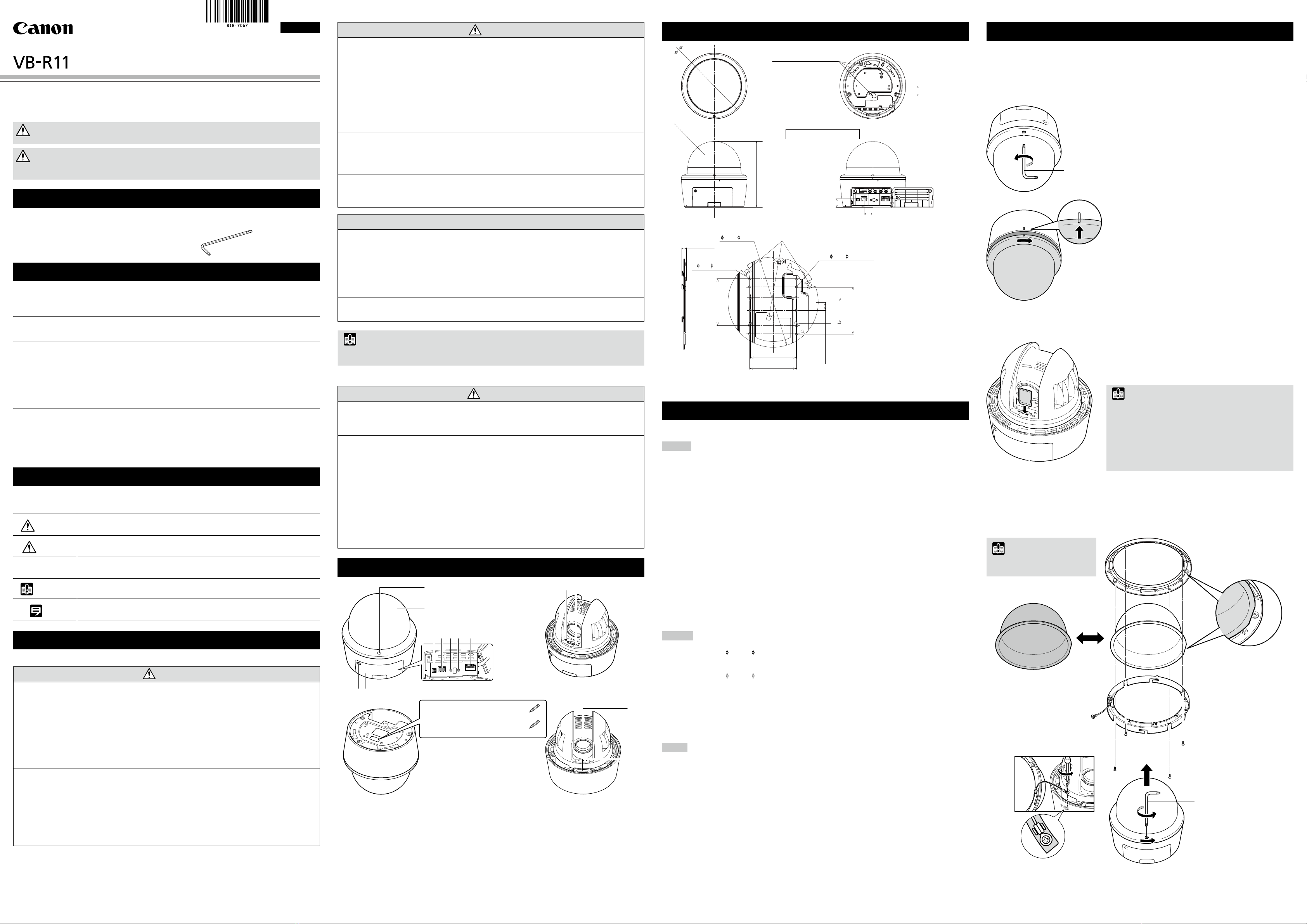
Part Names
2
5 6 7 8 9
3 4
1
12
10 11
13
Serial_ _ _ _ _ _ _ _ _ _ _ _ _ _ _ _ _
MAC_ _ _ _ _ _ _ _ _ _ _ _ _ _ _ _ _ _
1. Dome case lock screw / 2. Dome case / 3. Interface cover lock screw / 4. Interface cover
5. Power connection terminal / 6. 100Base-TX LAN connector /
7. Audio input terminal (common LINE IN and MIC IN) / 8. Audio output terminal (LINE OUT) /
9. External device I/O terminals / 10. Reset switch / 11. Memory card slot / 12. Lens unit /
13. Mounting-release button
External Dimensions
Camera mounting tab slots
30 (1.18)
(RJ45 connector location)
Cover at open position
Camera mounting tab
R80 (R3.15)
199 (7.83)
26 (1.02)
27 (1.06)
15(0.59)
(*4)
85.7(3-3/8) (*3)
85.7
(3-3/8)
(*4)
8.2 (0.32)
83.5
(3-9/32)
(*4)
85.7
(3-3/8)
(*3,*4)
199
( 7.83)
Unit: mm (in.)
165 ( 6.50)
10- 4.5 ( 0.18) (*2)
Unit: mm (in.)
46
(1-13/16)
(*4)
4- 4.5( 0.18) (*1)
*1 Ceiling mount holes
*2 Junction box fixing holes
*3 Ceiling mount holes position
*4 Junction box fixing holes
position
Specifications
Please refer to the installation procedures or the Appendix – Specifications for specifications not
listed below.
Camera
Lens 30x optical zoom (20x digital zoom) lens with auto focus
Viewing Angle For 16:9 aspect ratios
Horizontal: 58.4° (W) – 2.1° (T)
Vertical: 34.1° (W) – 1.2° (T)
For 4:3 aspect ratios
Horizontal: 58.4° (W) – 2.1° (T)
Vertical: 45.0° (W) – 1.6° (T)
Min. Subject Illumination
Day Mode (color):
0.03 lux (F1.4, shutter speed 1/30 sec., when smart shade control is off, 50IRE)
Night Mode (monochrome):
0.002 lux (F1.4, shutter speed 1/30 sec., when smart shade control is off, 50IRE)
When using the Dome Unit (Smoked) (sold separately)
Day Mode (color):
0.06 lux (F1.4, shutter speed 1/30 sec., when smart shade control is off, 50IRE)
Night Mode (monochrome):
0.004 lux (F1.4, shutter speed 1/30 sec., when smart shade control is off, 50IRE)
Pan Angle Range 360° continuous panning
Tilt Angle Range 180º (ceiling-mounted position: 0º – 180º)
– When the horizontal direction of the camera is 0°
– When the tilt angle is between angles below, the dome cover can cause a line to appear in the
video, as well as a decline in the video quality.
0° – 12° (168° – 180°) (W)
0° – 5° (175° – 180°) (T)
Interface
Network Terminal
LAN x 1 (RJ45, 100Base-TX (auto/full-duplex/half-duplex))
Audio Input Terminal 3.5 mm ( 0.14 in.) mini-jack connector (monaural)
(Common for LINE IN & MIC IN)
LINE IN (connect to an amplifier microphone) or MIC IN (connect to a microphone w/o amplifier)
Switch LINE IN/MIC IN in the setting page.
Audio Output Terminal
3.5 mm ( 0.14 in.) mini-jack connector (monaural)
(LINE OUT) LINE OUT (connect to an amplifier speaker)
External Device I/O Terminal
Input x 2, Output x 2
Memory Card* SD Memory Card, SDHC Memory Card, SDXC Memory Card Compatible.
Recorded Content: Log, Video (Event, Manual, ONVIF, Timer, Upload
)
Frame Rate: Max. 1 fps (JPEG)
Max. 30 fps (H.264)
* Use CLASS 10 cards. Cards under CLASS 10 may not have sufficient performance for tasks
such as video recording.
Others
Operating Environment Temperature:
AC, DC, PoE: -10°C – +50°C (+14°F – +122°F)
Humidity: 5% – 85% (without condensation)
Storage Environment Temperature: -30°C – +60°C (-22°F – +140°F)
Humidity: 5% – 90% (without condensation)
Installation Method Ceiling mount
Canon will not guarantee proper operation if the cameras are installed on surfaces where the
angle is more than ±5° from horizontal or on walls, because this will put a heavy load onto
sliding mechanical parts and may affect durability.
Power Supply
PoE: PoE power supply via LAN connector (IEEE802.3at Type1 Class 0 compliant)
AC Adapter: PA-V18 (100 – 240 V AC) (sold separately)
External power source: 24 V AC/12 V DC
Power Consumption PoE: Max. approx. 9.5 W*
AC Adapter PA-V18: Max. approx. 9.6 W (100 V AC)
Max. approx. 9.8 W (240 V AC)
DC: Max. approx. 8.8 W
AC: Max. approx. 9.2 W
* Class 0 power sourcing equipment (requests 15.4 W)
Weight Approx. 1990 g (4.39 lb.)
Before installing the camera
Set the IP address and other network information on the camera using the “Camera Management
Tool” on the Setup CD-ROM.
For details on how to operate the “Camera Management Tool”, please refer to the “Camera
Management Tool User Manual”.
Dome case attachment/detachment method
Attaching the dome case
1. Align the marks on the camera and the dome case and
turn it clockwise to attach it.
2. Tighten the dome case lock screw with the dedicated
wrench.
Dome case removal method
Loosen the dome case lock screw with the dedicated
wrench and rotate it counter-clockwise to remove it.
Dedicated wrench
Using a Memory Card
Remove the dome case and place the memory card in the
memory card slot.
To remove the memory card, push it in all the way until the
card slightly pops out and remove.
Important
• Insert a memory card before installing the camera.
• When using a memory card with the camera for the first time,
it is recommended to format the card after inserting it into
the camera (please refer to the “Operation Guide” > “Setting
Page” > “Memory Card”).
• Always unmount the memory card before removing it (please
refer to the “Operation Guide” > “Setting Page” > “Memory
Card”).
Memory card slot
Using the Dome Unit (sold separately)
Remove the dome case from the camera, then remove the dome cover holder and dome flange,
and replace with the smoked dome.
Important
• Take care when replacing so as
not to scratch the dome cover.
Dome flange
Dome cover
Dome cover holder
Dedicated wrench
Smoked dome cover
ENGLISH
The contents of this guide are subject to change without any prior notice.


