3
Installation and safety instructions
Battery charger CFHC-1 has been designed to provide safety and reliable. It is necessary to observe the
following precautions in order to avoid damage to persons and to the battery charger:
• Read the installation instructions contained in this Manual carefully. For further information put the
Manual in a proper place.
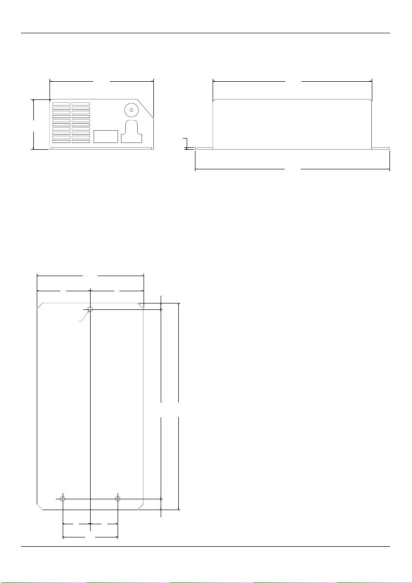
• Fix the battery charger to a stable surface through the appropriate holes inserted on the fixing
flanges. In case of installation on a vehicle it is advisable to use antivibration supports.
• Preferably the charger should be installed in the vertical position with fans facing up. The horizontal
installation is allowed. Never install in the vertical position with fans facing down.
• Ensure all ventilation ports are not obstructed, to avoid the overheating. Do not put the battery
charger near heat sources. Make sure that free space around the battery charger is sufficient to
provide adequate ventilation and an easy access to cables sockets.
• Protect the battery charger from ingress of water. Do not pour liquids inside the case.
• Verify that the available supply voltage corresponds to the voltage that is stated on the battery
charger name plate. In case of doubt, consult a retailer or local Electric Supply Authority.
• For safety and electromagnetic compatibility, the battery charger has a 3-prong plug as a safety
feature, and it will only fit into an earthed outlet. If you can not plug it in, chances are you have an
older, non-earthed outlet; contact an electrician to have the outlet replaced. Do not use an adapter to
defeat the earthing.
• To avoid damaging the power cord, do not put anything on it or place it where it will be walked on. If
the cord becomes damaged or frayed, replace it immediately.
• If you are using an extension cord or power strip, make sure that the total of the amperes required by
all the equipment on the extension is less than the extension’s rating.
• Disconnect the mains supply before connecting or disconnecting the links to the battery.
• To recharge Lead Acid batteries: WARNING: Explosive Gas – Avoid flames and sparks. The battery
must be positioned in a correctly cooled place.
• Do not use to charge batteries installed on board of thermal engine cars.
• Avoid recharging of non-rechargeable batteries.
• Verify that the nominal voltage of the battery to be re-charged corresponds to the voltage stated on
the battery charger name plate.
• Verify that the selected charging curve is suitable for the type of battery to be re-charged. In case of
doubt, consult Your retailer. ZIVAN S.r.l. will not accept any responsibility in case of mistaken choice
of the charging curve that may cause irreversible damage to the battery.
• In order to avoid voltage drop, thereby assuring 100% charge at the battery, the output cables must
be as short as possible, and the diameter must be adequate for the output current.
• In the case of thermal compensation of the battery voltage, it is necessary to place the thermal
sensor in the area of highest battery temperature.
• Do not try to service the battery charger yourself. Opening the cover may expose you to shocks or
other hazards.
• If the battery charger does not work correctly or if it has been damaged, unplugged it immediately
from the supply socket and from the battery socket and contact a retailer.
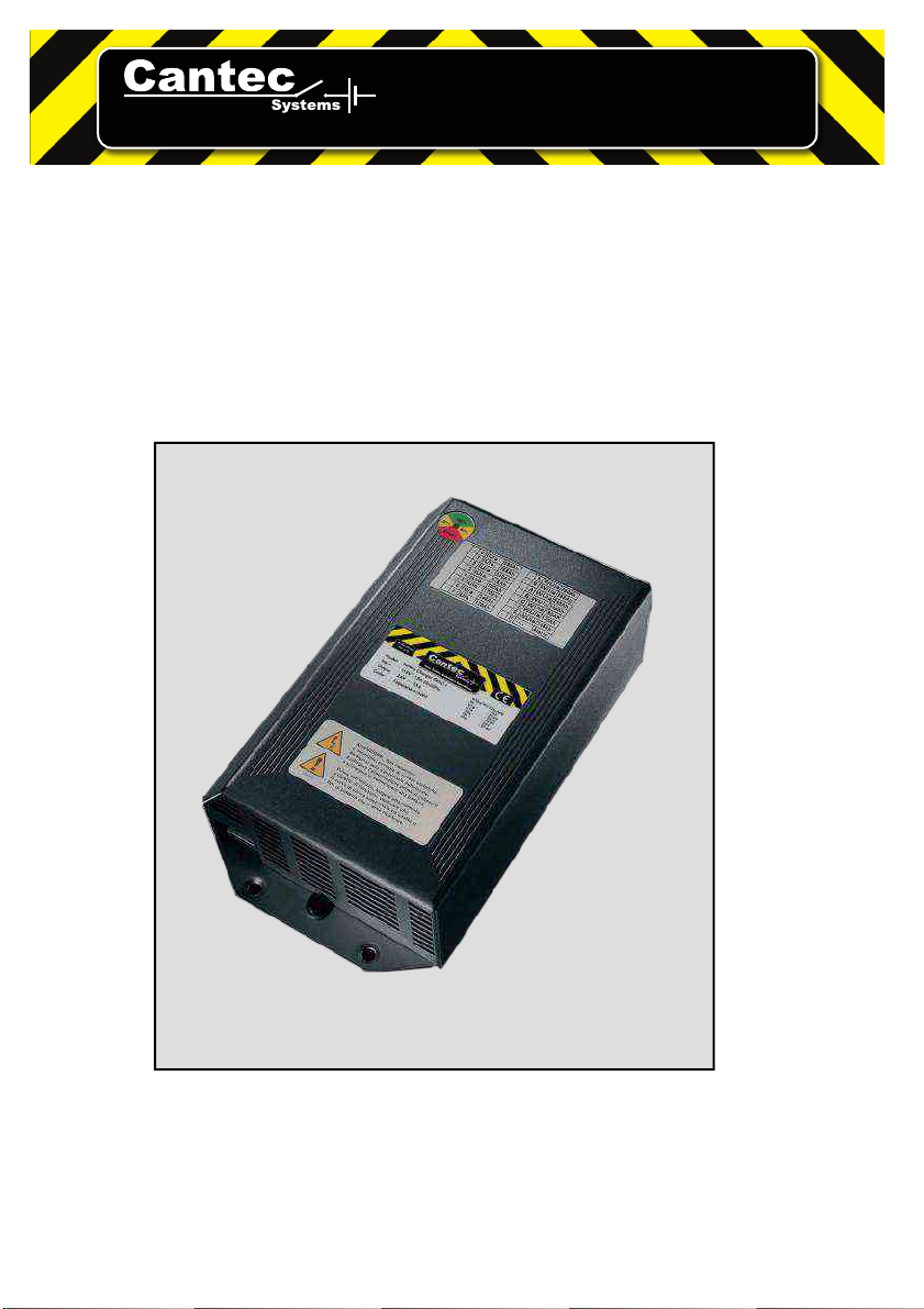
Battery charger CHFC-1