Cantherm JUMBO 400 User manual

L-L 265.00-BM 1 / 24
INSTRUCTIONS MANUAL
MANUEL D'INSTRUCTIONS
SPACE HEATER
GENERATEUR D'AIR CHAUD
JUMBO 400 - JUMBO 600 -
JUMBO 800
FR
EN

L-L 265.00-BM 2 / 24
WARNING
BEFORE USING THE HEATER, READ AND UNDERSTAND ALL INSTRUCTIONS AND FOLLOW
THEM CAREFULLY.
THE MANUFACTURER IS NOT RESPONSIBLE FOR DAMAGES TO GOODS OR PERSONS DUE
TO IMPROPER USE OF THE UNITS.
GENERAL HAZARD WARNING
FAILURE TO COMPLY WITH THE PRECAUTIONS AND INSTRUCTIONS PROVIDED WITH THIS
HEATER, CAN RESULT IN DEATH, SERIOUS INJURY AND PROPERTY LOSS OR DAMAGE
FROM HAZARDS OF FIRE, EXPLOSION, BURN, ASPHYXIATION, CARBON MONOXIDE
POISONING, AND / OR ELECTRICAL SHOCK.
ONLY PERSONS WHO CAN UNDERSTAND AND FOLLOW THE INSTRUCTIONS SHOULD USE
OR SERVICE THIS HEATER.
IF YOU NEED ASSISTANCE OR HEATER INFORMATION SUCH AS AN INSTRUCTION
MANUAL, LABEL, ETC., CONTACT THE MANUFACTURER.
WARNING: FIRE, BURN, INHALATION AND EXPLOSION HAZARD
KEEP SOLID COMBUSTIBLES, SUCH AS BUILDING MATERIALS, PAPER OR CARDBOARD, AT
SAFE DISTANCE AWAY FROM THE HEATER AS RECOMMENDED BY THE INSTRUCTIONS.
NEVER USE THE HEATER IN SPACES WHICH DO OR MAY CONTAIN VOLATILE OR
AIRBORNE COMBUSTIBLES, OR PRODUCTS SUCH AS GASOLINE, SOLVENTS, PAINT
THINNER, DUST PARTICLES OR UNKNOWN CHEMICALS.
WARNING
NOT FOR HOME OR RECREATIONAL VEHICLE USE. INSTALLATION OF THIS HEATER IN A
HOME OR RECREATIONAL VEHICLE MAY RESULT IN A FIRE OR EXPLOSION, PROPERTY
DAMAGE, PERSONAL INJURY OR LOSS OF FIRE.
WARNING
IMPROPER INSTALLATION, ADJUSTMENT, ALTERATION, SERVICE OR MAINTENANCE CAN
CAUSE INJURY OR DEATH.
READ THE INSTALLATION, OPERATING AND MAINTENANCE INSTRUCTIONS THOROUGHLY
BEFORE INSTALLING OR SERVICING THIS EQUIPMENT.
FOR YOUR SAFETY
IF YOU SMELL GAS:
1. OPEN WINDOWS
2. DO NOT TOUCH ELECTRICAL SWITCHES
3. EXTINGUISH ANY OPEN FLAME
4. IMMEDIATELY CALL YOUR GAS SUPPLIER
FOR YOUR SAFETY
DO NOT STORE OR USE GASOLINE OR OTHER FLAMMABLE VAPOURS AND LIQUIDS IN
THE VICINITY OF THIS OR ANY OTHER APPLIANCE.

L-L 265.00-BM 3 / 24
WARNING
The heater is designed and approved for use as a construction heater in accordance with Standard
ANSI Z83,7 CGA 2.14.
CHECK WITH YOUR LOCAL FIRE SAFETY AUTHORITY IF YOU HAVE QUESTIONS ABOUT
APPLICATIONS.
Other standards govern the use of fuel gases and heat producing products in specific
applications.Your local authority can advise you about these.
WARNING
This heater can be washed, provided that:
A. The heater is disconnected from the electrical supply.
B. All access panels are securely closed.
C. Water spray nozzle shall not discharge within 6 feet of the heater.
D. The heater is not reconnected to electrical supply until thoroughly dried.
Improper cleaning of the heater can cause severe personal injury or property damage due to water
and/or cleaning solutions:
A. In electrical components, connections and wires causing electrical shocks or component
failure.
B. On gas control components causing corrosion which can result in gas leaks and fire or
explosion from the leak.The hose assembly must be protected from the traffic, building
materials and contact with hot surfaces both during use andwhile in storage.
WARNING
Proper gas supply must be provided to the inlet of the appliance.
Refer to rating plate for proper gas supply pressure.
Gas pressure in excess of maximum inlet pressure specified at the appliance inlet can cause fire or
explosions, leading to serious injury, death, building damage or loss of livestock.
Likewise, gas pressure below the minimum inlet pressure specified at the appliance inlet may cause
improper combustion,leading to asphyxation, carbon monoxide poisoning and therefore serious
injury or death to humans and livestock.
Position heater properly before use.
For either indoor or outdoor use adequate ventilation must be provided.
Minimum clearance from combustible materials and propane containers: 10 ft.
Do not operate heater with panels removed.
Not for use with ductwork.
To avoid injury from moving parts, disconnect all electrical power to equipment before opening
doors or removing panels.
WARNING
RETAIN THIS INSTRUCTION FOR FUTURE REFERENCE..

L-L 265.00-BM 4 / 24
CONTROL BOARD - SCHÉMA DE FONCTIONNEMENT
1 HOT AIR OUTFLOW
SORTIE AIR CHAUD
2 CHIMNEY
CHEMINEE
3 COOLING FAN
VENTILATEUR REFROIDISSEMENT
4 COMBUSTION CHAMBER
CHAMBRE DE COMBUSTION
5 BURNER
BRULEUR
6 THERMOSTATS L2 BOX
BOITIER THERMOSTATS L2
7 HOISTING BRACKETS
ÉTRIERS DE LEVAGE
8 SUPPORT/HANDLE
SUPPORT/POIGNEE
9 WHEEL
ROUE
10 BURNER BOX
BOÎTIER BRÛLEUR
11 BUFFER
PARE-CHOCS
12 ELECTRICAL PANEL BOX
BOÎTIER TABLEAU ÉLECTRIQUE
1
4
12
5
9
10
5
3
2
6
7
11
8
8

L-L 265.00-BM 5 / 24
CONTROL PANEL - TABLEAU DE COMMANDE
a HEATING-VENTILATION SWITCH
INTERRUPTEUR CHAUFFAGE-VENTILATION
b VOLTAGE LAMP
TEMOIN TENSION
c OVERHEAT THERMOSTATS CONTROL LAMP, L2
TEMOIN THERMOSTATS DE SURCHAUFFE, L2
d ROOM THERMOSTAT PLUG
PRISE THERMOSTAT D’AMBIANCE
e INTAKE FOR PRE-HEAT FILTER
PRISE POUR FILTRE PRÉCHAUFFAGE
f CABLE CLAMP FOR POWER CABLE
PRESSE-CÂBLES POUR CÂBLE D'ALIMENTATION
g TEMPERATURE CONTROLLER
THERMORÉGULATEUR
h BURNER LIGHT
VOYANT BRÛLEUR
i SAFETY THERMOSTAT RESET BUTTON, L2
POUSSOIR DE RÉARMEMENT THERMOSTAT DE SÉCURITÉ, L2
m BURNER RESET BUTTON / LAMP
TÉMOIN / POUSSOIR DE RÉARMEMENT BRÛLEUR
n ELECTRICAL PANEL BOX PANEL
PANNEAU BOÎTIER TABLEAU ÉLECTRIQUE
o ELECTRICAL PANEL
TABLEAU ÉLECTRIQUE
a b
d
c
f
g
i
h
e b m
n
o

L-L 265.00-BM 6 / 24
MANIFOLD ASSEMBLY – MANIFOLD ASSEMBLY
400 kBTU/h
600 kBTU/h
800 kBTU/h
a
f
f
f
c
c
d
d
d
d
d
a
a
a
e
e
e
a GAS SELECTOR VALVE / VALVE SÉLECTEUR GAZ
b MANIFOLD PRESSURE PORT / PORT PRESSION BRULEUR
c MANIFOLD PRESSURE REGULATOR / RÉGULATEUR PRESSION
d MAIN GAS VALVE / SOUPAPE PRINCIPALE GAZ
e INLET PRESSURE PORT / PORT PRESSION EN ENTRÉE
f SHUT OFF - FIRING VALVE / VALVE COUPURE

EN
L-L 265.00-BM 7 / 24
IMPORTANT
Before using the space heater, carefully read all of the instructions and follow them scrupulously. The manufacturer cannot be
held responsible for damage to persons and/or property caused by improper use of the equipment.
This instruction manual is an integral part of the equipment and must therefore be stored carefully and passed on with the unit in
the event of a change of ownership.
1. DESCRIPTION
Space heaters described in this manual, are designed for use in
medium to large-sized rooms and buildings where a fixed or mobile
heating system is required.
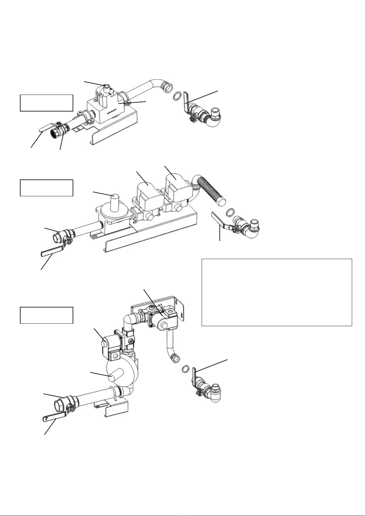
The air required for combustion is sucked directly by the burner (6)
installed on the heater, and can be supplied:
• from the outside by using the flexible connection tube (available
as an accessory), which avoids consuming oxygen in the room to
be heated, or
• from inside the room to be heated. In this case, the room must be
well ventilated to guarantee sufficient exchange of air.
The flow of hot air is moved by the high-efficiency fan (4): air is
heated by the thermal energy generated during la combustion and
heat from the smoke is transmitted to the fresh air through the
metal walls of the sealed combustion chamber and the heat
exchanger. After the combustion products are cooled, they are
conveyed to a discharge duct and eliminated through a chimney or
flue large enough to guarantee their removal.
The space heaters can work with burners having ON-OFF work
modes and fuelled by natural gas or propane.
Warning
Only burners approved by the manufacturer and listed in
the “TECHNICAL SPECIFICATION TABLE” can be used.
The heater’s certification and warranty will lapse if the
burner is replaced with a non-original model, even if it has
similar specifications.
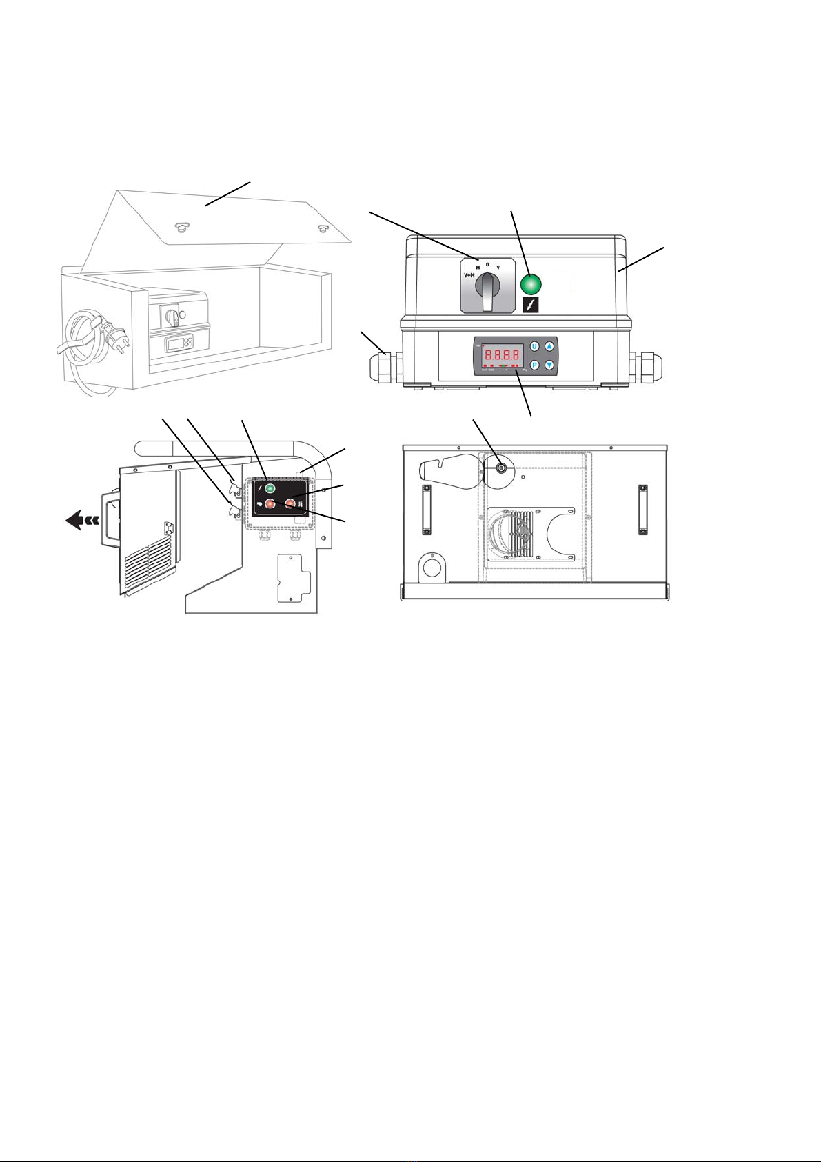
All of the space heaters are fit with an electronic device that
controls the flame and with:
• safety devices (safety thermostat with manual reset, flame
control, air pressure switch) that trip in case of serious
malfunctions and cause a safety stop. In this case the heater
stops, button (d) lights with a steady red light (Stop Light) and the
heater can resume operation only after the cause of the stop has
been identified and eliminated;
• control devices (temperature controller to control temperature of
air outflow, complete with hour counter, fan thermostat, burner
thermostat, voltage control) that trip in case of minor operating
faults or supply faults, causing temporary stop of the space
heater. In this case, the heater will restart automatically when the
required condition is restored.
The section “TROUBLESHOOTING” describes all possible operating
faults and their possible remedies.
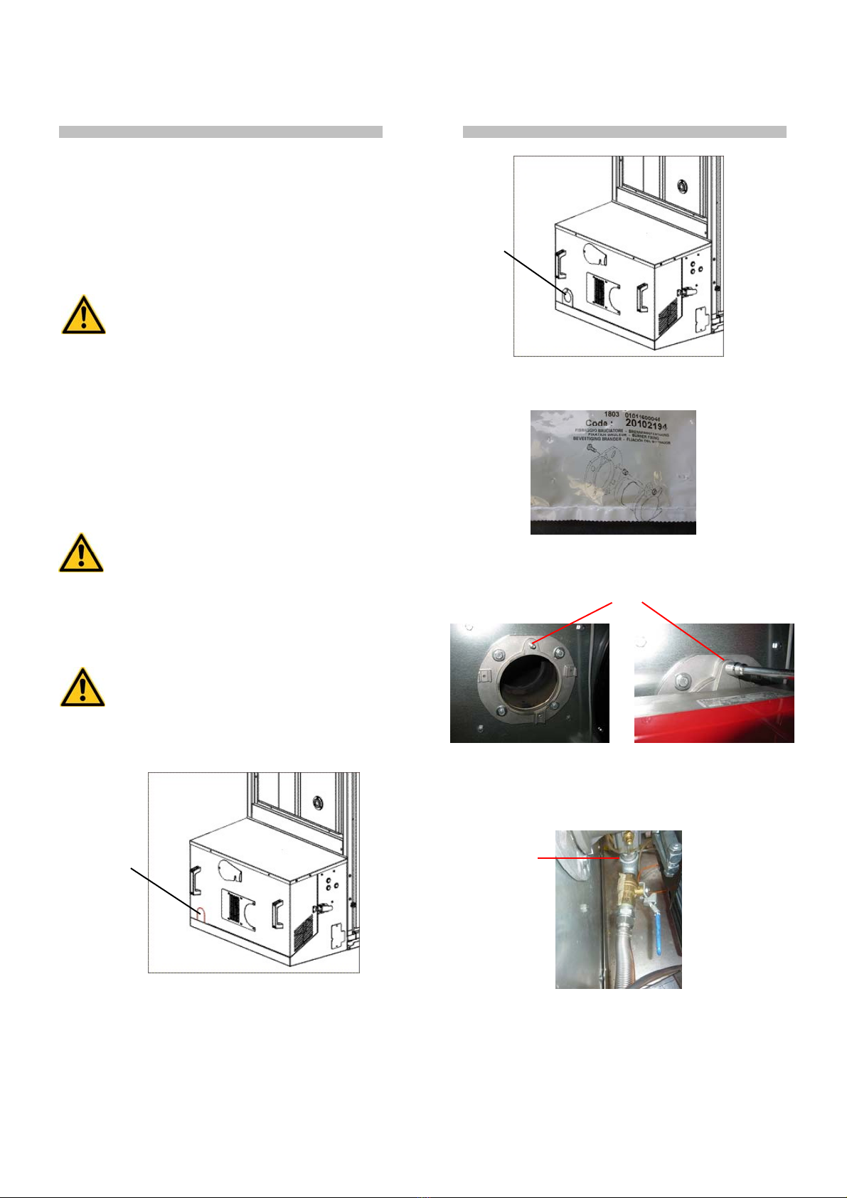
2. CONDITIONS OF SUPPLY
The heater is delivered with parts to be assembled and set as
described in chapter 4.
• Heater body
• Burner
• Air distribution connector
• Any required accessories (flue pipes, air distribution pipes, etc.)
Warning
Prior to installation, burner adjustment and ignition, the
space heater should be assembled in full.
All assembly operations should only be performed by
professionally qualified personnel only.
The following are also supplied:
• use and maintenance manuals for
• space heater
• burner
• manuals with drawings and spare part lists:
• space heater
• burner
Warning
All documents provided constitute an integral part of the
unit.
The documents should therefore be looked after with care
and supplied with the unit in the event of a change in
ownership.
Parts are to be transported and moved using either a manual or
automatic forklift truck with sufficient load capacity.
Warning
Never try to lift the heater manually. Doing so could cause
serious physical injury.
3. GENERAL ADVICE
The space heater must be installed, adjusted, and used in
conformity to national and local laws and regulations for its
operation.
General guidelines:
• Follow the instructions in this booklet very carefully;
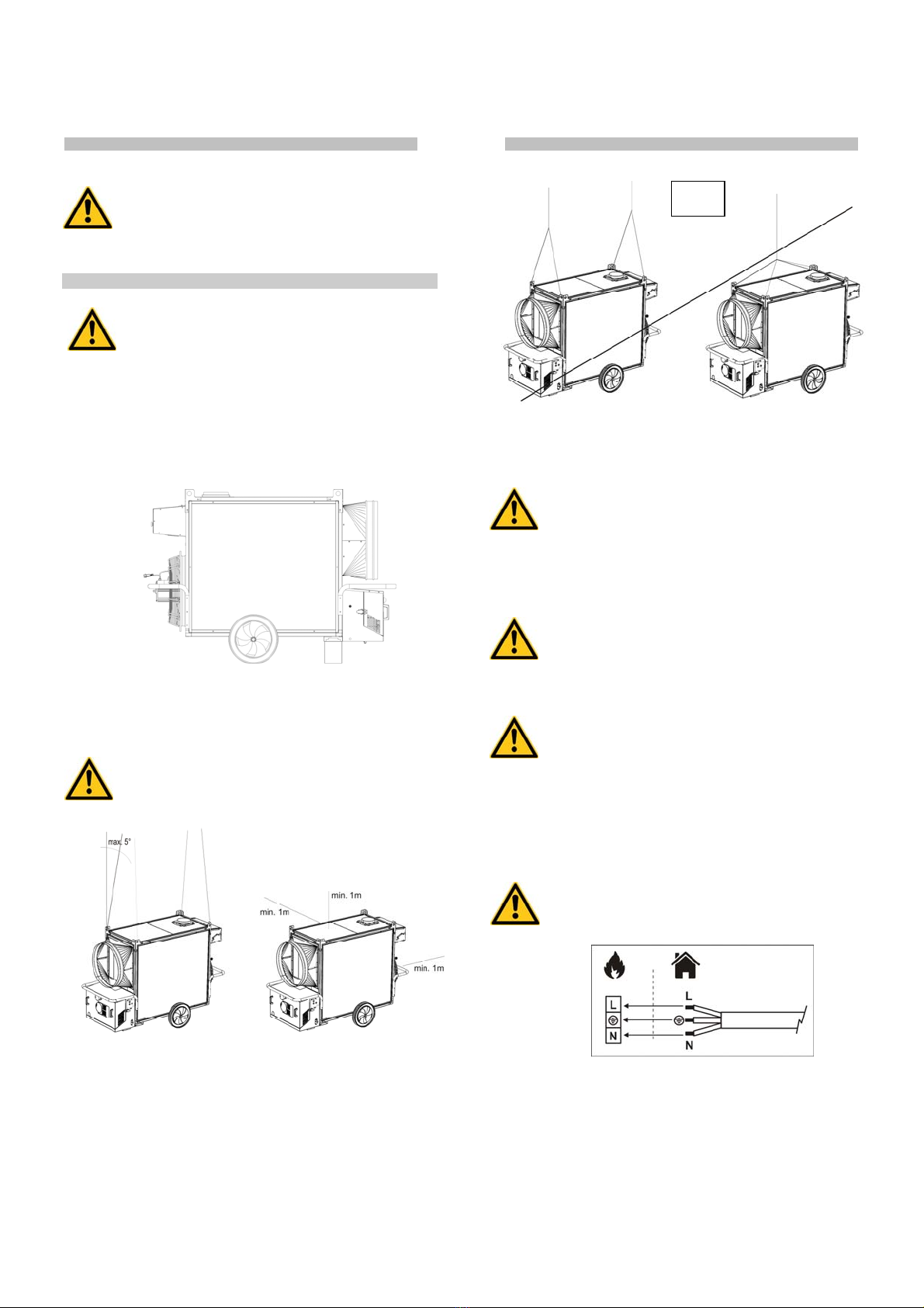
• The heater is not installed in an area where there is a high risk of
fire or explosions;
• Minimum clearances from combustible material must be:
1 m (3 feet) from side and rear (air inlet) of heater
1 m(3 feet) on top of heater
3 m (10 feet) on air outlet of heater.
• Keep inflammable material at a safe distance from the heater
(minimum 3 metres);
• Check that there is no overheating of walls, ceilings or floors made
of inflammable materials,
• All precautions have been taken to prevent fires;
• The room being heated must be sufficiently ventilated so that the
heater has enough air to function properly;
• The heater must be near a chimney or chimney flue and an
electrical panel conforming to declared specifications;
• Check the heater before switching it on and at regular intervals
during its use;
• After use, make sure the disconnecting switch is off.
When using any type of space heater it is obligatory:
• not to exceed the maximum heat output level of the furnace
(“TECHNICAL SPECIFICATION TABLE”);
• make sure that the air flow is not below the rated level; check that
there are no obstacles or obstructions to the air suction and/or
delivery ducts, such as sheets or covers on the equipment, walls
or large objects near the heater.

EN
L-L 265.00-BM 8 / 24
Warning
This unit may not be used by persons (including children)
with reduced physical, sensorial or mental capacities or
with limited experience and familiarity unless they are
under supervision or instructed on how to use the unit by
the person responsible for its safety.
4. INSTALLATION INSTRUCTIONS
Warning
All of the operations described in this section must be
performed by professionally qualified personnel only.
The installation shall be in accordance with National Fuel Gas Code
ANSI Z223.1/NFPA 54 and with CAN1-B149.1 Installation code.
An approved manual gas valve shall be provided by the installer.
4.1. INSTALLATION ON FLOOR OR CEILING
The space heater may be installed:
• on the floor in a stable position
• or suspended by hooking it to the ceiling using cables and/or
chains of an appropriate size and length secured to the four
suspension points.
Warning
Make sure that the ropes and/or chains form an angle not
more than 5° with vertical to the ceiling, that the ropes do
not cross, and that a different rope is used for each hook.
The minimum distance from surrounding walls and/or ceiling must
always be at least 1 metre.
4.2. POWER CONNECTIONS
Warning
The 120V unit is fitted with a proper power cord.
The 220V equipment is fitted with a temporary power
cable, used for the final control test at factory. The
temporary power cord must be removed and replaced with
a proper power cord whose type and dimension shall be in
accordance with national rules.
Warning
The power line of the generator must feature an earthlead
and a residual current circuit breaker.
The supply cable must be connected to a switchboard
with sectioning switch.
Warning
When installed, the appliance must be electrically
grounded in accordance with local codes, or in the
absence of local codes, with the National Electrical Code,
ANSI/NFPA 70, and/or the CSA C22.1, Canadian Electrical
Code, if an external electrical source is utilized.
The electrical power cable must be connected in conformity to the
polarity specified on the main terminal board of the electrical panel:
phase (L) and neutral (N).
Warning
If polarities L and N are incorrect, the space heater may
stop a few seconds after it is switched on for the first
time.
Before switching on the heater and, therefore, before plugging it into
the electrical power supply, check that the power supply
specifications are the same as those stated on the identification
plate.
NO

EN
L-L 265.00-BM 9 / 24
Any room thermostat or other accessories (such as a timer) are
connected to the system by connecting the electrical cable to the
thermostat plug (c):
• Take the plug (c) out of the electrical panel, open the plug and
remove the jumper between terminals 2 and 3.
• Connect the thermostat electrical cable to terminals 2 and 3 of the
thermostat plug (c).
• Close the plug again and plug it back into the panel.
Warning
Never attempt to switch the heater on or off by connecting
the room thermostat (or other control devices) to the
electrical power line.
The installation and connection of all the other accessories are
described in the specific instructions included with each accessory,
together with operating instructions.
The electrical diagram shown in this manual refers to the electrical
connection only.
4.3. CONNECTION TO HOT AIR DELIVERY DUCTS
The space heater is set to operate with direct distribution of air.
Nevertheless, it can be connected to appropriately sized air
distribution channels, if required, with maximum diameter and
length as shown in the “TECHNICAL SPECIFICATION TABLE.”
Warning
Before starting the heater, check that the direction of
rotation of the fan matches the direction shown on the fan
itself.
The air distribution channels can be connected by using the various
accessories supplied, placing the connector head-on to one or more
outlets chosen as needed.
4.4. MOUNTING THE RIELLO GAS BURNER
Warning
Riello gas burners are supplied pre-fit with a nozzle for
natural gas and a gas selector valve for switching from
natural gas to propane or viceversa (see paragraph 4.8).
• Remove the box cover and, with an appropriate tool, eliminate
metal parts B by following the pre-cut line already traced on the
cover.
• Take flange D with seal E and assemble them on the burner cover
by using the self-threading screws supplied.
• Consult the user manual of the burner; and fit the burner fixing
screw onto the burner plate according to the instructions
• Secure the burner plate to the machine by using the 4xM8 screws
and the D8 x D24 washers;
• Open the box containing the gas valve group + the gas selector
valve group
• Connect the gas selector valve group to the burner (use sealant
approved for gas connection on thread L)
• Insert the burner and fix it to the plate by tightening the nut
supplied onto the screw G;
• Locate the black cable with Wieland plug running out of the
electrical panel and insert the plug into the socket H on the
burner;
G
B
D - E
L

EN
L-L 265.00-BM 10 / 24
• Secure the gas valve group to the machine using the M8 and M5
screws.
• Remove flange D with seal E previously assembled on the burner
cover and insert it by sliding it on the gas delivery pipe.
• Connect the stainless steel flexible hose to the gas valve selector
group, taking care to properly insert the N gas seal:
• Locate the cable with Wieland plug running out of the gas valve
group and insert the plug into the burner socket;
• Close the burner cover;
• The burner is not pre-adjusted by the manufacturer and must be
set according to data reported in Table of Technical
Characteristics of the user manual: follow the instructions in the
manual to complete the connection of the machine to the gas
supply system and for commissioning
Warning
Check all threaded connections on the gas line.
When commissioning, check for any gas leaks or
seepages using soap and water
4.5. CONNECTION TO FUEL SUPPLY
Warning
The heater must be installed, set up, and used in
compliance with all applicable regulations.
Warning
Before installing, check the gas supply conditions
required for the type of gas chosen.
The gas supply pipe must be properly sized, conform to the installed
thermal power, and guarantee the necessary conditions for gas
supply.
Warning
The gas supply pressure must be guaranteed during
heater operation and not with the heater off.
The space heater has a gas ramp with: gas filter, pressure regulator,
safety electrovalve, work electrovalve, pressure stabilizer, pressure
valve.
It is good practice for the installer to set up the supply line as
follows:
1: filter-pressure regulator or filter 2: antivibration joint
3: stopcock 4: gas ramp
Parts (1), (2) and (3) are available as accessories and are not
supplied with the heater.
When the line has been connected:
• Bleed the gas supply pipe;
• Check that the gas pipe is sealed.
• Open the gas stopcock and check the seal of all connections to
the heater.
In case of connection of heater to natural gas, the installation shall
conform with local codes or, in the absence of local codes, with the
National Fuel Gas Code ANSI Z223.1/NFPA 54 and the Natural Gas
and Propane Installation Code, CSAB149.1.
In case of connection to a propane supply cylinder:
(a) the installation must conform with local codes or, in the absence
of local codes, with the Standard for the Storage and Handling of
Liquified Petroleum Gases, ANSI/NFPA 58 and the Natural Gas
and Propane Installation Code, CSA B149.1.
(b) to determine size and capacity of the cylinder(s) and for any
specific requirements consult your LP gas supplier. In any case
propane tank should not be lower than 100 lb (90 liters)
(c) the cylinder supply system shall be arranged to provide for
vapour withdrawal from the operating cylinder;
(d) the gas shall be turned off at the propane supply cylinder when
the heater is not in use;
H
N
D - E

EN
L-L 265.00-BM 11 / 24
(e) when the heater is to be stored indoors, the connection between
the propane supply cylinder and the heater must be disconnected
and the cylinders removed from the heater and stored in
accordance with Standard for the Storage and Handling of
Liquified Petroleum Gases, ANSI/NFPA 58 and CSA B149.1,
Natural Gas and Propane Installation Code.
The appliance and its individual shut-off valve must be
disconnected from the gas supply piping system during any
pressure testing of that system at test pressures in excess of 1/2
psi (3.5 kPa).
The appliance must be isolated from the gas supply piping system
by closing its individual manual shut-off valve during any pressure
testing of the gas supply piping system at test pressures equal or
less than 1/2 psi (3.5 kPa).
A minimum 1/8” NPT plugged tapping, accessible for test gauge
connection, must be installed immediately upstream of the gas
supply connection to the appliance.
4.6. CONNECTION TO EXHAUST DUCT
Exhaust ducts must be in steel and conform to local/national rules.
Efficient combustion and trouble-free working of the burner depend
on efficient flue draft.
The unit must be connected to the chimney flue in compliance with
current legal regulations and in line with the following guidelines:
• The path of the flue pipe smoke should be as short as possible
and should slant upwards (minimum height 1 m);
• There should be no sharp curves in the pipes, and the diameter of
the pipes must never be reduced;
• there must always be a wind deflector to prevent the entrance of
rain and to prevent smoke from being blocked by the wind;
• flue draft must at least equal the level in the Technical
Specifications.
• When the heater is connected to a flue pipe, the flue pipe shall
terminate in a vertical section at least two feet long and sufficient
draft shall be created to assure safe and proper operation of the
heater;
• every heater must have its own chimney;
The following diagrams show possible flue positions:
A) Minimum 1 m
B) As short as possible
C) Minimum 1 m
D) Chimney draught H shape
4.7. FIRST START-UP
The heater is supplied after a complete functional test and it’s
therefore prearranged for one of the gas (natural or L.P.G.) indicated
in Tab. I: an adhesive label applied on the manual gas selector valve
(Fig. 4) indicates the working gas (usually it’s natural gas). Should it
necessary to change the kind of gas (from natural gas to L.P.G or
viceversa) follow the detailed instructions indicated in section
“CHANGING TYPE OF GAS”.
Only when the heater has been prearranged according to the proper
working gas it will be possible to carry out the following operations:
• Leak away some gas from the feed pipe;
• Check that the pipe is gas proof;
• Open the gas stopcock and start the hot air generator;
For installation in the U.S.A. at elevation above 2,000 feet (610 m),
the appliance shall be derated 4 per cent for each 1,000 feet (305 m)
of elevation above sea level.
For installation in Canada at elevation above 2,000 feet to 4,500 feet
above sea level, the heater is deratedy reducing the input for the
appropriate fuel in accordance with the rating plate manifold
pressure.
Warning
THE CONVERSION SHALL BE CARRIED OUT BY A
MANUFACTURER’S AUTHORIZED REPRESENTATIVE, IN
ACCORDANCE WITH THE REQUIREMENTS OF THE
MANUFACTURER, PROVINCIAL OR TERRITORIAL
AUTHORITIES HAVING JURISDICTION AND IN
ACCORDANCE WITH THE REQUIREMENTS OF THE
CAN/CGA-B149.1 OR CAN/CGAB149.2 INSTALLATION
CODES.
A conversion label shall be applied adiacent to the Rating Label:
THIS APPLIANCE HAS BEEN CONVERTED FOR USE
AT AN ALTITUDE OF ___________ FEET (ABOVE 2000 FEET)
Orifice size: ______________________________________
Manifold pressure: ______________________________________
Input rate: ______________________________________
Date of conversion: ______________________________________
Type of fuel: ______________________________________
Converted by: ______________________________________
For installation in Canada at elevation above 4,500 feet above sea
level, consult Provincial or Territorial Authorities having jurisdiction.
You can continue and start up the heater only after it has been
prepared it according to the instructions for the work category to be
used.
4.8 CHANGING TYPE OF GAS
This operation may be carried out several times during the working
life of the machine and not only at initial start-up. Therefore, first of
all check the adhesive label attached to the manual gas selector
valve (a) in Fig. (2) to establish the original category of the gas and
then consult Tab. I to identify the supply pressure, the working
pressure, the use conditions of manual valve.
To change kind of gas it is necessary (Fig. 2):
• to remove the sticker on the manual gas selector valve stating the
gas used at that time,
• to remove the screw under the sticker and turn the manual handle
on the correct side according to the condition described in Tab.I and
by following instruction:

EN
L-L 265.00-BM 12 / 24
Fig. 4
• After having moved the handle into the opposite position, put
again the fixing screw and a new sticker on it, stating the gas which
has to be used (a number of different stickers are supplied with the
machine)
Warning
Burner pressure shall not be adjusted: the heater is ready
to run on the new gas
Should it necessary to check the burner pressure:
• connect a manometer to the pressure port located on the burner
support ,
• carry out the pressure reading on the manometer and turn the
pressure regulator (c) if necessary to obtain the correct burner
pressure value indicated in Tab. I
4.9. REGULATING COMBUSTION AND ANALYSING COMBUSTION
PRODUCTS
Warning
The first start-up should always be carried out by a
specialised technician checking the correctness of the
combustion parameters.
Warning
The burner settings are pre-set at the factory and may not
comply with those required, therefore, the settings need to
be checked and, where necessary, corrected.
The adjustment values (gas fuel pressure, burner gas pressure,
combustion head position, air adjustment) for each of the burners
approved for these units are indicated in the “TECHNICAL
SPECIFICATION TABLE”.
The probe used to periodically check combustion and flue smoke
temperatures is to be inserted as indicated:
Combustion is clean and stable when combustion values are as
follows:
NATURAL GAS
G20 - G25
LIQUID GAS
G30 - G31
Index Bacharach - 0 (white)
CO28.5 ÷ 9.5 % 11.5 ÷ 12.5 %
Oxygen (O2) 4.5 ÷ 6 % 4.5 ÷ 6 %
COma 100 ppm 100 ppm
You may have to change the burner settings due to the fuel used
and/or installation conditions (high altitude, air suction pipe with or
without Snorkel, etc.) if combustion parameters are not correct.
When inspection tests are completed, the hole drilled for the probe
must be sealed with a material that is resistant to high
temperatures and that ensures the tube remains airtight.
5. OPERATING INSTRUCTIONS
5.1. START
To start the heater:
• Raise panel (n) on the electrical panel box;
• Make sure the switch (a) is set to “0”;
• Supply electrical power to the space heater by pulling up the
disconnecting switch on the electric power panel: the green lamp
(b) will light up indicating that power is being supplied to the
panel;
•Turn switch (a) to position H or H+V: the burner will begin the start-
up and pre-wash cycle, after which the flame will ignite; after the
combustion chamber has been heating for a few minutes, the
main fan will start up;
Warning
The fan runs continuously in H+V mode, even when the
desired room temperature has been reached, and the
burner turns off.
Warning
In H mode, the fan only runs when the combustion
chamber is sufficiently hot. Therefore, when the desired
room temperature has been reached, the burner turns off
and the fan keeps running only until the combustion
chamber has cooled completely.
• If the heater does not work during the start cycle or work cycle,
consult “TROUBLESHOOTING” to find the cause of the
malfunction.
Warning
If the burner goes into safety stop (lamp m) push reset
button (d) for 3 seconds to restart the heater..
Warning
If the safety thermostat goes into safety stop (lamp h),
push reset button (i) for 3 seconds to restart the heater.
Warning
NEVER do more than two restarts in a row: unburned fuel
can accumulate in the combustion chamber and suddenly
flare up at the next restart.
5.2. STOP
Stop the heater by turning switch (a) to “0” position or, if the heater
is in automatic mode, by setting the room thermostat to a lower
temperature: the burner shuts off and lamp (f) goes out. The fan
keeps working, starting and stopping several times until the
combustion chamber has cooled completely.

EN
L-L 265.00-BM 13 / 24
Warning
Never stop the heater by simply turning off the
disconnecting switch on the panel.
The electrical supply must be disconnected ONLY when
the fan has come to a complete stop.
5.3. VENTILATION
To run the heater only in continuous ventilation mode, turn switch
(a) to the position with the symbol V.
5.4. TEMPERATURE CONTROLLER
The heater is equipped with a temperature controller (g) with LCD
screen, which displays and controls the following parameters:
• Display of air outflow temperature
• Display of hours of operation
• Control of trip temperature of fan thermostat
• Control of trip temperature of burner thermostat
Display of air outflow temperature
The screen displays the measured temperature in [°C]:
Display of hours of operation
Press key (a) twice: the screen shows the operating time in hours
[h]:
Warning
The time shown is not actual heating time, but connection
time to the electrical power supply line.
Reset the counter as follows:
• Turn the heater’s main switch to position “0” (OFF)
• Press button P on the temperature controller for at least 3
seconds: the word “PASS” will flash for 5 seconds
• Enter code “-481” by pressing key (b) several times until obtaining
the number required; press key P to confirm and go to the next
number
• Lastly, press key U: the display again shows the air outflow
temperature
Control of trip temperature of fan thermostat
The temperature controller is programmed to start and stop the
main fan automatically when the combustion chamber reaches the
set temperature. This prevents cold air from blowing when the
burner starts and the combustion chamber is not yet hot enough,
and ensures that residual heat in the heater is dissipated when the
burner stops.
The temperature is factory-set to 35°C, with hysteresis of 5°C.
Red LED “OUT 1” shows the operating state of the fan thermostat:
• LED ON: the fan is on
• LED OFF: the fan is off
Control of trip temperature of burner thermostat
The temperature controller is programmed to start and stop the
burner automatically when the combustion chamber reaches the set
over-temperature. This prevents excessive overheating of the
combustion chamber and subsequent tripping of safety thermostat
L2, which blocks operation of the heater (see chapter 7 for details
on operating problems that cause tripping of safety thermostat L2).
The temperature is factory-set to 95 °C, with hysteresis of 5°C.
Red LED “OUT 2” shows the operating state of the burner
thermostat, while the LED group “- = +” indicates the current
temperature compared to the set temperature:
• if the red arrow at the symbol “-“ is ON, it means that the
temperature is below the set value and, therefore, the thermostat
is ON, i.e., the burner is ON.
• if the green LED at the symbol “=1“ is ON, it means that the
temperature is at the set value.
• if the red arrow at the symbol “+“is ON, it means that the
temperature is above the set value and, therefore, the thermostat
is OFF, i.e., the burner is OFF.
Warning
The trip temperatures of the fan thermostat and burner
thermostat should be changed only if absolutely
necessary. Contact the manufacturer for information
needed to reprogram the temperature controller..
6. MAINTENANCE
Warning
All of the operations described in this section must be
performed by professionally qualified personnel only.
The following procedures must be done at regular intervals to
ensure efficient operation of the heater. Make sure you have
detached the electrical power line from the heater before starting
any work.
Warning
Before doing any maintenance:
• Stop the heater as indicated in the “STOP” paragraph;
• Switch off the power supply by means of the cut-off on
the electrical panel;
• Wait until the heater cools.
b
a

EN
L-L 265.00-BM 14 / 24
Procedure
Periodic maintenance
Every day
Every week
Every six
months
Every year
Check heater X
Check gas supply line X
Clean exterior of heater X
Clean motor and fan X
Check gas supply pressure X
Check electrical connections X
Check and test burner X
Check thermostats X
Clean interior of heater X
Inspect and clean combustion
chamber X
6.1. CHECKING THE HEATER AND THE GAS SUPPLY LINE
Perform the following checks:
• Make sure the heater is not installed where there may be a risk of
fire or explosion
• Make sure that flammable materials are kept a safe distance away
• If you smell:
• Open the windows immediately
• Do not touch electrical switches
• Close the gas stopcock
• Find and repair the source of the gas leak
• Do not use the heater if any removed panels have not been
remounted
• Make sure the room to be heated is sufficiently ventilated
• Make sure that the air intake and outlet are completely
unobstructed
• Make sure that the heater is not covered by any sheets or covers;
• Check that the heater is in a fixed and stable position;
• Make sure the heater is constantly monitored during operation and
checked before being started
6.2 CLEANING THE EXTERIOR OF THE HEATER
To ensure efficient operation, clean the following parts:
• Burner:
• Remove all external dirt and debris
• Make sure the air inlet is not obstructed.
• Pipes, connectors and joints:
• Clean with a cloth.
• External body:
• Clean with a cloth.
• Air inlet/outlet:
• Remove all dirt and debris
• Make sure the air inlet is not obstructed.
6.3 Cleaning the motor and the fan
Clean the fan blades and the motor as follows:
• Remove the fan group fixing screws and then remove the fan
group.
• Clean the motor with compressed air.
• Clean the fan blades with a hard brush.
• Reinstall the fan group.
6.4 CHECKING THE ELECTRICAL CONNECTIONS
After detaching the power cable, check all electrical connections as
follows:
• Make sure that all connections are complete and tight.
• If there are traces of dirt or corrosion, clean or replace the
connections if necessary.
• Replace any damaged wires or connectors if necessary.
6.5 CHECKING AND TESTING THE BURNER
To reach the burner:
• Remove the burner fixing screw.
• Remove the burner and follow the checking and cleaning
instructions in the burner manual.
• Reinstall the burner.
• Run the procedures described in paragraphs 4.7 and 4.8 to
measure combustion parameters and check that combustion is
stable and clean.
6.6 CHECKING THE THERMOSTATS
Inspect the thermostats as follows:
• Remove any air outlet connection ducts
• Find the thermostats fixed to the internal panel of the space
heater.
• Clean with a dry cloth, taking care not to cut or bend the capillary
tube.
6.7 CLEANING THE INTERIOR OF THE HEATER
For thorough cleaning, the heater can be cleaned and washed inside
and outside with water. It is however necessary to ensure that:
• the electrical cable is disconnected and unplugged from the
socket
• completely close all access panels
• do not use water jets at a pressure exceeding 70 bar at a distance
less than 30 cm
• completely dry all parts before reconnecting the electrical cable.
6.8 CLEANING THE COMBUSTION CHAMBER
To maintain the burner’s high efficiency and prolong its life, the
procedure described in this paragraph must be done at least once at
the end of the work season or more frequently if there is an
excessive build-up of soot. Excessive soot may be caused by poor
chimney draught, poor fuel quality, poor regulation of the burner, or
more or less frequent alternation of burner starts and stops.
Pay attention during operation: pulsations at start may be due to
excessive amounts of soot.
To access the heat exchanger (1), take off the rear panel (3), remove
the smoke box inspection panel (2), and then remove baffle plates
(7).
To access the combustion chamber (4) remove the burner (5).
Clean with compressed air or, if necessary, with a metal brush to
remove any deposited soot and combustion residues.
Warning
After any technical work, always check that the heater
works correctly.
7. TROUBLESHOOTING
In the event of serious anomalies, various safety devices are able to
block the machine's operation and signal the same:
• on the electrical panel
the blocking signal following intervention by safety
thermostat L2: the reset button is located inside the burner
box.

EN
L-L 265.00-BM 15 / 24
• on the burner
the blocking signal following intervention by the burner's
flame control box.
Warning
NEVER do more than two restarts in a row: unburned fuel
can accumulate in the combustion chamber and suddenly
flare up at the next restart.
If the heater is still not working properly, please contact your
nearest dealer or authorized Service Centre.
FAULT CAUSE REMEDY
• The heater does not start:
lamp is off
• No power supply
• Check functioning and position of switch
• Check the mains
• Check power connections
• Check fuse
• The heater does not start:
lamp is on
• Switch (a) in wrong position • Select correct position
• Incorrect functioning of the room thermostat
• Check that thermostat connection plug is inserted
• Check thermostat electrical connection
• Check thermostat setting and correct it
• Check functioning of thermostat
• The burner goes on and off alternately and LED
OUT 2 on the temperature controller remains
ON.
• Insufficient gas supply • Check and clean gas filter.
• Clean and recalibrate the burner.
• Incorrect setting of burner • Clean and recalibrate the burner.
• The burner goes on and off alternately and LED
OUT 2 on the temperature controller is OFF
when the burner goes off.
• Burner thermostat has tripped due to
overheating
• Check correct position of air distribution channels
and opening of any flaps, openings, etc.
• Remove any foreign bodies trapped in the air ducts or
ventilation grilles
• The heater does not work:
the lamp on the electrical panel is on
• Manual reset safety thermostat has tripped due
to excessive overheating of combustion
chamber
• Check that the fan motor starts correctly and is not
obstructed
• Check that the fan motor is not burned out or that the
motor condenser is not broke
• Check burner calibration
• Check the path and correct discharge of fumes
• The heater does not work::
the lamp on the burner is steady on
• Burner's safety equipment has tripped • Refer to the burner manual for diagnosis and causes
• Fan noise or vibrations • Foreign bodies on fan blades • Remove foreign bodies
• Insufficienct air circulation • Eliminate all possible obstacles to proper air flow
• Insufficient heating • Insufficient burner capacity • Contact Customer Service

L-L 265.00-BM 16 / 24
WIRING DIAGRAM - SCHEMA ELECTRIQUE
M FAN MOTOR
MOTEUR VENTILATEUR
F FAN THERMOSTAT (setting: 30°C)
THERMOSTAT VENTILATEUR (régulation: 30°C)
FB FUSE
FUSIBLE
ST POWER LAMP
LAMPE TEMOIN MISE SOUS TENSION
L2 LIMIT THERMOSTAT WITH MANUAL RESTART
THERMOSTAT DE SECURITE A REARMEMENT MANUEL
RV HEATING-STOP-VENTILATION SWITCH
COMMUTATEUR CHAUFFAGE - ARRÊT – VENTILATION
SL OVERHEAT THERMOSTATS CONTROL LAMP
LAMPE TEMOIN SECURITE DE SURCHAUFFE
L1 BURNER THERMOSTAT (setting: 90°C)
THERMOSTAT BRULEUR (régulation: 90°C)
TA ROOM THERMOSTAT PLUG
PRISE THERMOSTAT D’AMBIACE
RE2 DELAYED IGNITION RELAY
RELAIS DE RETARD ALLUMAGE
R ANTI-CONDENSATION RESISTANCE
RÉSISTANCE ANTICONDENSATION
TM FANS TELE-CONTACTOR
TELERUPTEUR VENTILATEUR
RM FANS THERMAL RELAY
RELAIS THERMIQUE VENTILATEUR
ST POWER LAMP
LAMPE TEMOIN MISE SOUS TENSION
SM FAN STOP LAMP
TÉMOIN VENTILATEUR BLOQUÉ
BR BURNER
BRULEUR
PB7 BURNER PLUG
PRISE BRULEUR
RV HEATING-STOP-VENTILATION SWITCH
COMMUTATEUR CHAUFFAGE - ARRÊT - VENTILATION
120V, 1 ~, 60Hz

L-L 265.00-BM 17 / 24
WIRING DIAGRAM - SCHEMA ELECTRIQUE
M FAN MOTOR
MOTEUR VENTILATEUR
F FAN THERMOSTAT (setting: 30°C)
THERMOSTAT VENTILATEUR (régulation: 30°C)
FB FUSE
FUSIBLE
ST POWER LAMP
LAMPE TEMOIN MISE SOUS TENSION
L2 LIMIT THERMOSTAT WITH MANUAL RESTART
THERMOSTAT DE SECURITE A REARMEMENT MANUEL
RV HEATING-STOP-VENTILATION SWITCH
COMMUTATEUR CHAUFFAGE - ARRÊT – VENTILATION
SL OVERHEAT THERMOSTATS CONTROL LAMP
LAMPE TEMOIN SECURITE DE SURCHAUFFE
L1 BURNER THERMOSTAT (setting: 90°C)
THERMOSTAT BRULEUR (régulation: 90°C)
TA ROOM THERMOSTAT PLUG
PRISE THERMOSTAT D’AMBIACE
RE2 DELAYED IGNITION RELAY
RELAIS DE RETARD ALLUMAGE
R ANTI-CONDENSATION RESISTANCE
RÉSISTANCE ANTICONDENSATION
TM FANS TELE-CONTACTOR
TELERUPTEUR VENTILATEUR
RM FANS THERMAL RELAY
RELAIS THERMIQUE VENTILATEUR
ST POWER LAMP
LAMPE TEMOIN MISE SOUS TENSION
SM FAN STOP LAMP
TÉMOIN VENTILATEUR BLOQUÉ
BR BURNER
BRULEUR
PB7 BURNER PLUG
PRISE BRULEUR
RV HEATING-STOP-VENTILATION SWITCH
COMMUTATEUR CHAUFFAGE - ARRÊT - VENTILATION
240V, 1 ~, 60Hz

L-L 265.00-BM 18 / 24
TECHNICAL SPECIFICATIONS JUMBO 400
Burner Model RIELLO R40-N400S
Burner Nozzle RIELLO G20
Nominal Heat Input [BTU/h] 400,000
Natural gas
Supply pressure [in w.c.] min 7" w.c.
max 10" w.c.
Normal
altitude 0 -
2,000 ft above
sea level
(U.S.A. and
Canada)
Heat input [BTU/h] 394,309
Manifold pressure [in w.c.] 3.60
Burner head position [N°] 4
Burner Air setting [N°] 4.7
Fuel consumption [CFH] 384.31
Altitude 2.000
- 4.500 ft
above sea
level (Canada
only)
Heat input [BTU/h] 354,878
Manifold pressure [in w.c.] 3.40
Burner head position [N°] 4
Burner Air setting [N°] Max
Fuel consumption [CFH] 345.88
L.P.G.
Supply pressure [in w.c.] min 8" w.c.
max 13" w.c.
Gas firing valve [in] 0.374
Normal
altitude 0 -
2.000 ft above
sea level
(U.S.A. and
Canada)
Heat input [BTU/h] 393,052
Manifold pressure [in w.c.] 2.40
Burner head position [N°] 4
Burner Air setting [N°] 4.7
Fuel consumption [CFH] 158.40
Altitude 2.000
- 4.500 ft
above sea
level (Canada
only)
Heat input [BTU/h] 353,747
Manifold pressure [in w.c.] 2.20
Burner head position [N°] 4
Burner Air setting [N°] max
Fuel consumption [CFH] 142.56
Air flow [cfm] 5,297
Fan Thermostat Setting [°F] 95
Burner Thermostat Setting [°F] 194
Power supply
Phase 1
Voltage [V] 120
Frequency [Hz] 60
Electric consumption [W] 950
[A] 8.2
Flue diameter [in] 5.91
Compulsory flue draft [in] 0.05
Maximum air temperature [°F] 250
Max. operating pressure elec. gas valve [psi] 0.5
Air distribution duct
Max Static pressure [in] 0.48
Max length 1 way - dia 20" [ft] 60
Max length 2 ways - dia 16" [ft] 36
Inlet flexible duct Max length 1 way - dia 26" [ft] 12
Noise level at 1 m [dBA] 68
Dimensions. L x W x H [in] 73.43 x 30.63 x 47.72
Weight [lb] 440.9

L-L 265.00-BM 19 / 24
TECHNICAL SPECIFICATIONS JUMBO 600
Burner Model RIELLO R40-N750S
Burner Nozzle RIELLO G20
Nominal Heat Input [BTU/h] 600,000
Natural gas
Supply pressure [in w.c.] min 7" w.c.
max 10" w.c.
Normal
altitude 0 -
2.000 ft above
sea level
(U.S.A. and
Canada)
Heat input [BTU/h] 596,549
Manifold pressure [in w.c.] 2.00
Burner head position [N°] 3
Burner Air setting [N°] 3.4
Fuel consumption [CFH] 581.42
Altitude 2.000
- 4.500 ft
above sea
level (Canada
only)
Heat input [BTU/h] 536,894
Manifold pressure [in w.c.] 1.88
Burner head position [N°] 3
Burner Air setting [N°] max
Fuel consumption [CFH] 523.28
L.P.G.
Supply pressure [in w.c.] min 8" w.c.
max 13" w.c.
Gas firing valve [in] 0.386
Normal
altitude 0 -
2.000 ft above
sea level
(U.S.A. and
Canada)
Heat input [BTU/h] 593,609
Manifold pressure [in w.c.] 1.60
Burner head position [N°] 3
Burner Air setting [N°] 3.4
Fuel consumption [CFH] 239.22
Altitude 2.000
- 4.500 ft
above sea
level (Canada
only)
Heat input [BTU/h] 534,248
Manifold pressure [in w.c.] 1.40
Burner head position [N°] 3
Burner Air setting [N°] Max
Fuel consumption [CFH] 215.30
Air flow [cfm] 7,063
Fan Thermostat Setting [°F] 95
Burner Thermostat Setting [°F] 194
Power supply
Phase 1
Voltage [V] 120
Frequency [Hz] 60
Electric consumption [W] 1,350
[A] 12.0
Flue diameter [in] 7.87
Compulsory flue draft [in] 0.05
Maximum air temperature [°F] 250
Max. operating pressure elec. gas valve [psi] 5
Air distribution duct
Max Static pressure [in] 0.60
Max length 1 way - dia 28”/26" [ft] 60
Max length 2 ways - dia 20" [ft] 36
Max length 4 way - dia 14" [ft] 30
Inlet flexible duct Max length 1 way - dia 28" [ft] 12
Noise level at 1 m [dBA] 68
Dimensions. L x W x H [in] 83.66 x 36.22 x 55.65
Weight [lb] 595.25

L-L 265.00-BM 20 / 24
TECHNICAL SPECIFICATIONS JUMBO 800
Burner Model RIELLO R40-N900S
Burner Nozzle RIELLO G20
Nominal Heat Input [BTU/h] 800,000
Natural gas
Supply pressure [in w.c.] min 7" w.c.
max 10" w.c.
Normal
altitude 0 -
2.000 ft above
sea level
(U.S.A. and
Canada)
Heat input [BTU/h] 802,180
Manifold pressure [in w.c.] 2.68
Burner head position [N°] 5
Burner Air setting [N°] 5.2
Fuel consumption [CFH] 772.0
Altitude 2.000
- 4.500 ft
above sea
level (Canada
only)
Heat input [BTU/h] 721,962
Manifold pressure [in w.c.] 2.56
Burner head position [N°] 5
Burner Air setting [N°] Max
Fuel consumption [CFH] 694.80
L.P.G.
Supply pressure [in w.c.] min 8" w.c.
max 13" w.c.
Gas firing valve [in] 0.464
Normal
altitude 0 -
2.000 ft above
sea level
(U.S.A. and
Canada)
Heat input [BTU/h] 805,499
Manifold pressure [in w.c.] 2.20
Burner head position [N°] 5
Burner Air setting [N°] 5.2
Fuel consumption [CFH] 317.16
Altitude 2.000
- 4.500 ft
above sea
level (Canada
only)
Heat input [BTU/h] 724,950
Manifold pressure [in w.c.] 2.00
Burner head position [N°] 5
Burner Air setting [N°] Max
Fuel consumption [CFH] 285.44
Air flow [cfm] 10,005.8
Fan Thermostat Setting [°F] 95
Burner Thermostat Setting [°F] 194
Power supply
Phase 1
Voltage [V] 240
Frequency [Hz] 60
Electric consumption [W] 3,300
[A] 15.5
Flue diameter [in] 7.87
Compulsory flue draft [in] 0.05
Maximum air temperature [°F] 250
Max. operating pressure elec. gas valve [psi] 5
Air distribution duct
Max Static pressure [in] 0.80
Max length 1 way - dia 28”/26" [ft] 90
Max length 2 ways - dia 24" [ft] 45
Max length 4 way - dia 18" [ft] 45
Max length 5 way - dia 14" [ft] 36
Inlet flexible duct Max length 1 way - dia 28.8" [ft] 18
Noise level at 1 m [dBA] 71
Dimensions. L x W x H [in] 91.93 x 38.98 x 62.34
Weight [lb] 773.82
This manual suits for next models
2
Table of contents
Other Cantherm Heater manuals
Popular Heater manuals by other brands

Rointe
Rointe Tovare electric OVAL 500 instruction & installation guide

Arlec
Arlec Simone user manual

Grill'D
Grill'D Dubravo mini Short Installation and operation manual

Nevir
Nevir NVR-9547QS instruction manual

Honeywell
Honeywell 360 SURROUND HEAT HHF360 Series owner's manual

Alliance Products
Alliance Products DALPH1002 Operation manual

STIEBEL ELTRON
STIEBEL ELTRON CFK 5 Operation and installation

Somogyi
Somogyi home FKIR 452 instruction manual

Steffes
Steffes 3120 Owner's and installer's manual

Powrmatic
Powrmatic NVx10 User, installation and servicing instructions

Lynx
Lynx LHEM48 Care & use/installation

Omega
Omega Altise OC1005 instruction manual