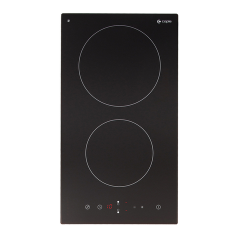
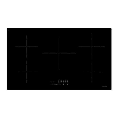
Caple C901I User manual

C901I
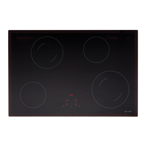
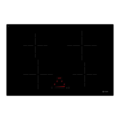
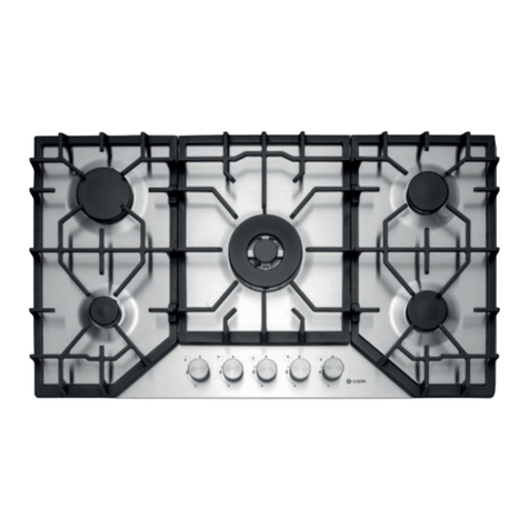
Caple Sense 90cm Touch Control Induction Hob
Service Manual

INDUCTION HOB G5 –TC SLIM SLIDER
1. To detect the wrong breakdowns :
1-1 Connection to the electric network:
Control the tightening of the screws of the connection box
Control the section of the cables used (see manual of use)
Control if the earth wire (green/yellow) is connected
1+2 = phase
4 = neutral
3 = no connection
Earth = obligatory
Alimentation cable: advised with fasten terminal wires (see photograph).
Tightening of the screws: either with a cross screwdriver (PZ N°2), or with a
torx screwdriver (T20 footprint) according to the type of terminal block.
- The checking of the connection and tightening has to be made before any intervention
on the hob.
- A bad tightening can be at the origin of a breakdown
If a bridging is not made correctly or if a screw is badly tightened, there can be the
following symptoms:
- If the terminals 1 or 4 are wrong connected, the hob does not switch on (no
reaction) because the touch control is not supplied.
- If the terminal 2 is wrong connected, “E5” will appear on the right hand side
displays on the right side.
BRIDGE
EARTH
Torx screw terminal block
Philips screw terminal block
3
2
1
4
EARTH
BRIDGE
Caple C901I Induction Hob

1-2 Installation :
Control the installation of the gasket under the glass.
If the glass is glued with silicone and in case of an after sales service: leave
the glass in place and dismount the steel case under the work plan.
Control the ventilation of the air coming in of the ventilator (minimum 20 mm
of space).
1-3 Quality of the pans :
Control if the pan is compatible with induction.
- either a „magnet“ must remain hung on the bottom of the pan
- or put a little water that must quickly boil at the power level „9”.
The functioning of an induction generates a certain sonority. This one
depends on the pans used.
Use only pans with flat bottoms. Others risk damaging the hob.
BAD GOOD
1-4 Use :
To start the hob it is necessary to press the key [0/I] during 2 to 3 seconds.
During the first times of use, the cooking appliance will release an smell of
„new“.
1-5 Ventilation :
The ventilation starts as soon as two heating zones are switched on.
This ventilation goes on cooling the heating zones even after the stop of
cooking.
1-6 Securities :
In case of overflow, the hob stops as soon as 2 keys at least of the control
panel are covered.
Caple C901I Induction Hob

In case of overheating of the heating zones, an automatic and progressive
reduction of the power takes place.
2. To determine the breakdown according to the indications of the
control panel.
2-1 Normal Display (according to the models)
Display Designation Description
0. Zero The heating zone is activated.
1…9 Power level Selection of the cooking level.
U No Pan detection No pan or inadequate pan.
A Heat accelerator Automatic cooking.
H Residual heat The heating zone is hot.
P Booster The booster is activated.
Double booster The double booster is activated.
U Keep warm Maintain automatically of 42, 70, or 94°C.
II Pause The hob is in pause.
2-2 Display of an error message :
Display Designation Description
E Error message Electronic hardware failure.
Er Error message Electronic software or TC failure.
Example of error display 31 : “Er”blinks with “31”
Caple C901I Induction Hob

2-3 Fast starting :
When the hob is connected to the electric network, the displays’segments scroll
clockwise.
After that, press the key [0/I] (On/Off), « 0 » appears.
If no handling is made within 20 seconds, everything switches off.
So, slide on the « slider » to regulate gradually from 1 to 9, or press the selected
level for a direct access before 20 seconds (First put a pan with a little water.
The bottom of the pan has to be cleaned to avoid from any scratching).
If no pan is put on the selected cooking zone, or if the pan is taken away during
the cooking, or if the pan is not adapted to induction, you will have the following
display:
slider
Caple C901I Induction Hob

PROCEDURE OF CONFIGURATION (E4) - TC SMART SLIDER
A. Disconnect the hob from the electrical network.
B. Connect the network and take into account that the configuration setting has to be made in a
maximum time of 2 minutes (If the time goes over, the procedure must be begun again from
stage A).
C. Do not switch on the hob by pressing key [ ].
D. Press and keep the finger on key [ ] until you hear a “Beep”.
E. Then, press on each display in the order « A-B-C-D-E-F » until you hear a “Beep”.
F. Remove your fingers from the touch control, then push again on touch [ ] during few
seconds, until blinking [ E ] symbols appears.
G. Wait until [ E ] symbols stop blinking. After few seconds, [ E ] are automatically
transformed in [ C ]. The existing setup has been cancelled
H. Take a ferromagnetical pot with a minimum diameter of 16 cm. Select a cooking zone by
pushing on the corresponding [ C ] display. Place the pot on the area to be set. Wait until
the [ C ] display becomes a [ - ]. The selected cooking zone is now configured.
I. Follow the same procedure for each cooking zone with a [ C ] display.
All the cooking zones are configured once all the displays are turned off.
Please use the same pot for the whole procedure.
Never put several pots together on the zones during the setup-process.
The hob is now ready to be used.
Caple C901I Induction Hob

ERROR CODES
Legend:
Visual Control
No appropriated measure
Measure with multimetre
Error Code
Description
Potential Failure
Measure
What to do…
E blinking No error!
IHE configurations have
been erased
You are in the configuration menu:
See description of the configuration
procedure
C No error!
Cooking zone can be
Configured
You are in the configuration menu:
See description of the configuration
procedure
- No error!
Cooking zone is configured
You are in the configuration menu:
See description of the configuration
procedure
C blinking No error!
Cooking zone can be
configured
You are in the configuration menu:
See description of the configuration
procedure
TC = Touch Control panel
Cable LIN = White Cable 0.25 mm2 (ex : connection between TC and Filter Board PCB).
IHE = Induction Heating Element
Caple C901I Induction Hob
Error Code
Description
Potential Failure
Measure
What to do…
E 2
Temperature sensor
indicates overheat of
induction coil
IHE over temperature
Wrong algorithm calculated
over-temperature at coil
sensor PT-1000 (only for
cooking level 9)
Cooking zone has overheated
(maybe pot boiled without
food...)
A cool down is necessary Error is
disappearing when cooling down
Replace IHE with sensor if E2 reappears
after complete cooling down of cooktop.
E 3
Not adapted pan
or
Component failure
Some pans lose their magnetic
properties due to a overheat of
the bottom
The pan generates
interferences which disturb the
functioning of the induction.
Some bad pans may destroy
some electronic components.
Employment of suitable pan
⇨Replace the pan
Replace IHE
E 4
IHE is not configured
Communication failure
between TC and IHE
Component failure
Defective or missing Lin Bus
cable between CU and IHE
Missing voltage supplying of
the IHE
Failure on the IHE
Configure again, with the manual procedure
Check and/or change the Lin Bus cable
Check the voltage of the IHE
Replace the IHE
E 5 Communication failure
between TC and IHE
Defective Lin Bus cable
Absence of power supply
IHE not connected
Check the mains connection
Check and/or change Lin Bus cable
Replace the IHE
Caple C901I Induction Hob
Error Code
Description
Potential Failure
Measure
What to do…
E 6 Network failure Frequency problem
Overvoltage
Check the frequency and voltage
Replace the IHE
E 7 Unknown error Compatibility problems
between IHE and TC Replace IHE or TC
E 8 Fan failure Fan or control electronics
defect Replace IHE
E 9 Temperature probe PT 1000 Temperature probe PT 1000 is
defective Replace IHE
E A Hardware failure Hardware failure Replace IHE
E C Configuration failure 2 cooking zones are connected
on the same key Configure again with the manual procedure
E H Fixed resistor recognition
If there is no temperature
change at the cook place after
activation of cooktop within 5
minutes, error display shows
message “E H“
Induction cooktop has to cool down
Caple C901I Induction Hob

Error Code
Description
Potential Failure
Measure
What to do…
No display /
Function
Wrong connection
Error on Touch Control
Defect mains connection
Component part error on TC
Component part error on IHE
As soon as the hob is installed, please check
if it works properly. If you cannot turn on the
appliance, please double check the electrical
connections on both sides of the power cord.
A wrong connection that lasts more than 30
minutes will cause permanent damage that
is not covered by the warranty.
Check the mains connection
replace TC
replace IHE
Review or replacement of Lin Bus Cable
Incorrect pot detection Pan not adapted
Component failure on IHE
Use an adapted pan
Replace IHE
Cyclic bar
display
Er31
Er47
TC
Defective or missing Lin Bus
cable between CU and IHE
TC failure
Reconfigure the TC
Review or replacement of Lin Bus Cable
Replace TC
Caple C901I Induction Hob
Error Code
Description
Potential Failure
Measure
What to do…
Er22
Key evaluation defect, Touch
Control switches off after
3,5-
7,5s.
Short circuit or interruption
around key evaluation Replace TC
Er 03 +
continuously
“sound”
Or symbol:
Continuous key activation,
Control switches off after
10s
Liquid or cookware on glass
above control Clean glass ceramics
Er 20
Flash error
Data not plausible
Programming options
wrong
Component part error on
Touch Control replace Touch Control
Cooking level
back to 0 Power level returns
automatically to zero Component part error on
IHE Replace IHE
L No mistake! Safety device for children
activates Desactivate the safety device for children
(see instruction manual)
Caple C901I Induction Hob
X6
X6
L1
N
N
L1
X2.1
X1.4
TC
CB
1
2
4
X6
N
L1
X19
X19
WIRING DIAGRAM
IHE : Induction Heating Element
TC : Touch Control
CB : Connection Box
IHE
IHE
IHE
IHE
IHE
Caple C901I Induction Hob
Other manuals for C901I
1
Table of contents
Other Caple Hob manuals