
Item Part Code Description
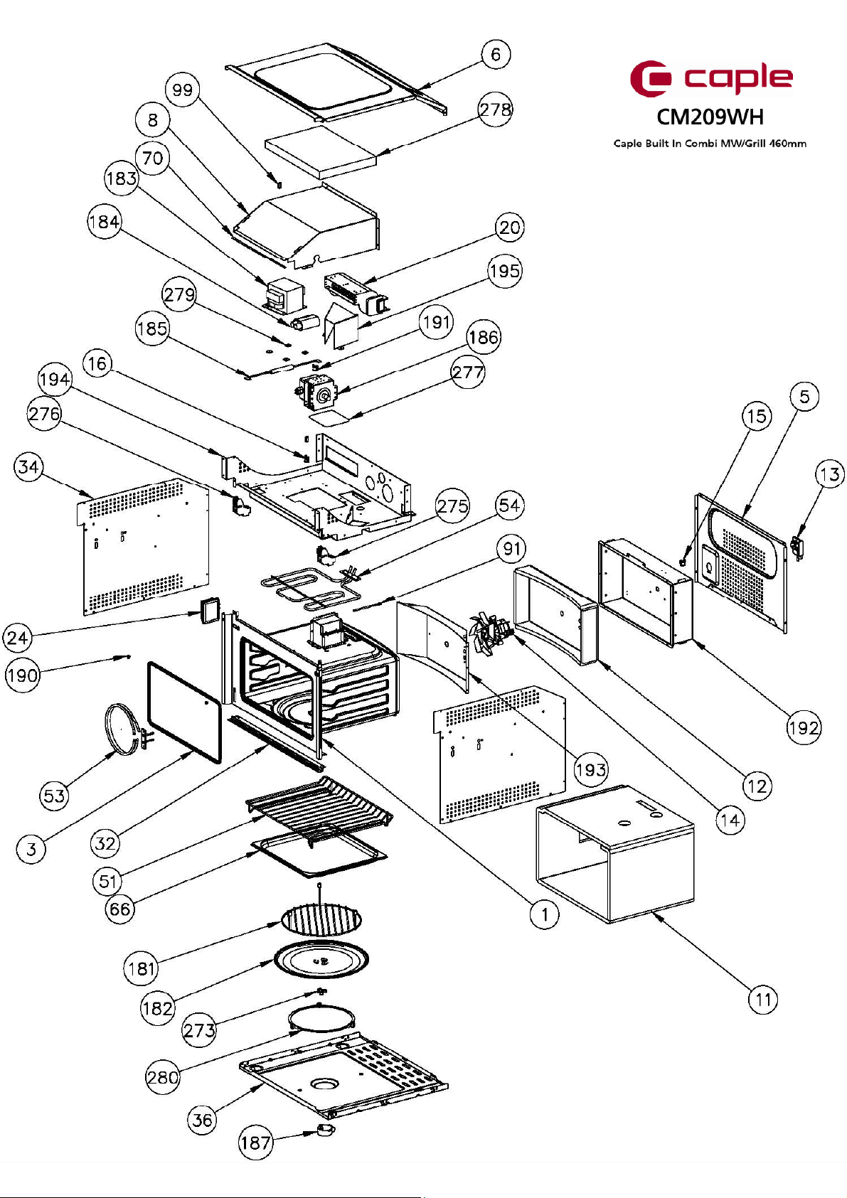
142703120 MUFFLE
3a 12381850 MUFFLE GASKET (until 23/03/14)
3b 12382130 MUFFLE GASKET (from 24/03/14)
512111260 BACK SHIELD
612111170 TOP SHIELD
812111860 AIR CONVEYOR F45N µONDE
11 12381530 FIBERGLASS SHELL
12 12380980 FIBERGLASS REAR
13 12530000 TERMINAL BLOCK/FASTEN CABLE 16A
14 12590191 RADIAL FAN
15 12540943 SAFETY THERMOSTAT PRESET T165¢C
16 12540944 SAFETY THERMOSTAT PRESET T110¢C
20a 12590150 TANGENTIAL COOLING FAN (until 10/07/14)
20b 12590270 TANGENTIAL COOLING FAN (from 11/07/14)
24 12540960 HALOGEN RECTANGULAR LAMP SOCKET 25W 230/240V
CM209WH
- Caple built in microwave
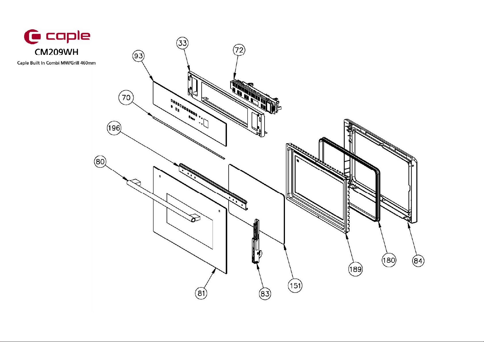
32 12192671 LOWER PROFILE F45N STEAM BLACK
33 12112541 COUNTER FRONTAL
34 12112400 LEFT-RIGHT SIDE SHIELD
36 12111810 BOTTOM SHIELD
51 12200460 SHELF
53 12570170 CIRCULAR HEATING ELEMENT 1500W
54 12570180 GRILL HEATING ELEMENT 1500W
66 12105390 TRAY H20 INOX GN2/3 F45N
70 12380950 ADHESIVE GASKET
72 42782041 INTERACTIVE POWER BOARD MICROWAVE 11F µF45N W/COOKBOOK
80 12740600 HANDLE SENSEHAN1 MAURICE LAY
81 42713330 GLASS DOOR
83 12600280 DOOR HINGE
84 12301000 INNER DOOR
91a 12541190 NTC PROBE (until 26/07/15)
91b 12542090 NTC PROBE (from 27/07/15)
93 42715689 FRONTAL GLASS
99 12380500 RUBBER FOOT FOR HINGE
151 12323500 3rd INNER GLASS THERMO REFLECTIVE
180 12381000 DOOR GASKET
181a 12702000 ROUND SHELF H75 (until 06/10/13)
181b 42702000 ROUND SHELF H75 (from 07/10/13)
182 12380930 FLAT GLASS SWIVEL
183 12541110 TRANSFORMER
184 12541120 CAPACITOR 2100Vac 50/60Hz 1.05µF
185 12541130 FUSE CARRIER + FUSE 0.8A-5kV
186 12570160 MAGNETRON
187 12590140 GEARMOTOR
µ


M Service manual")


