Caple Sirocco Si800 User manual

Instruction manual for Sirocco 80 cm hood
Model code: Si800
Contact Caple on 08448003830 or for spare parts www.4caple.co.uk


- 3 -

- 4 -

- 5 -

- 6 -

- 7 -

- 8 -

GENERAL
Carefully read the following important information regarding
installation safety and maintenance. Keep this information
booklet accessible for further consultations. The appliance
has been designed for use in the ducting version (air exhaust
to the outside – Fig.1B), ltering version (air circulation on
the inside – Fig.1A) or with external motor (Fig.1C).
SAFETY PRECAUTIONS
1. Take care w hen the coo ker ho od is o peratin g
simultaneously with an open fireplace or burner that
depend on the air in the environment and are supplied by
other than electrical energy, as the cooker hood removes the
air from the environment which a burner or replace need
for combustion. The negative pressure in the environment
must not exceed 4Pa (4x10⁻⁵ bar). Provide adequate
ventilation in the environment for a safe operation of the
cooker hood. Follow the local laws applicable for external
air evacuation.
Before connecting the model to the electrical supply:
- Check the data plate (positioned inside the appliance) to
ascertain that the voltage and power correspond to the
network and the socket is suitable. If in doubt ask a qualied
electrician.
- If the power supply cable is damaged, it must be replaced
with another cable or a special assembly, which may be
obtained direct from the manufacturer or from the Technical
Assistance Centre.
- This device must be connected to the supply network
through eiter a plug fused 3A or hardwired to a 2 fase spur
protected by 3A fuse.
2. Warning !
In certain circumstances electrical appliances may be
a danger.
A) Do not check the status of the lters while the cooker
hood is operating.
B)Donottouchbulbsor adjacentareas, during orstraight
after prolonged use of the lighting installation.
C) Flambè cooking is prohibited underneath the cooker
hood.
D) Avoid free ame, as it is damaging for the lters and
a re hazard.
E) Constantly check food frying as the overheated oil
may become a re hazard.
F) Di sco nnec t th e el ec t ric al plug p rior to a ny
maintenance.
G) This appliance is not intended for use by young
children or inrm persons without supervision.
H) Young children should be supervised to ensure they
do not play with the appliance.
I) There shall be adequate ventilation of the room when
the cooker hood is used at the same time as appliances
burning gas or other fuels.
L) There is a risk of re if cleaning is not carried out in
accordance with the instructions.
This appliance conforms to the European Directive
EC/2002/96, Waste Electrical and Electronic Equipment
(WEEE). By making sure that this appliance is disposed of in
a suitable manner, the user is helping to prevent potential
damage to the environment or to public health.
The symbol on the product or on the accompanying
paperwork indicates that the appliance should not be treated
as domestic waste, but should be delivered to a suitable
electric and electronic appliance recycling collection point.
Follow local guidelines when disposing of waste. For more
information on the treatment, re-use and recycling of this
product, please contact your local authority, domestic
waste collection service or the shop where the appliance
was purchased.
INSTALLATION INSTRUCTIONS
• Assembly and electrical connections must be carried
out by specialised personnel.
• Wear protective gloves before proceeding with the
installation.
• Electric Connection
Note: Verify the data label placed inside the appliance:
- If the symbol appears on the plate, it means that no
earth connection must be made on the appliance, there-
fore follow the instructions concerning insulation class II.
- If the symbol DOES NOT appear on the plate, follow the
instructions concerning insulation class I.
Insulation class II
The appliance has been manufactured as a class II, therefore
no earth cable is necessary.
The plug must be easily accessible after the installation of
the appliance. If the appliance is equipped with power cord
without plug, a suitably dimensioned omnipolar switch
with 3 mm minimum opening between contacts must be
tted between the appliance and the electricity supply in
compliance with the load and current regulations.
The connection to the mains is carried out as follows:
BROWN = Lline
BLUE = Nneutral
Insulation class I
Warning:
This is a class I, appliance and must therefore be connected
to an eecient earthing system.
The appliance must be connected to the electricity supply
as follows:
BROWN = Llive wire
BLUE = Nneutral
YELLOW / GREEN = earth
The neutral wire must be connected to the terminal with
the N symbol while the YELLOW / GREEN, wire must be
connected to the terminal by the earth symbol .
Warning:
When connecting the appliance to the electricity supply,
make sure that the mains socket has an earth connection.
After tting the ducted cooker hood, make sure that the
electrical plug is in a position where it can be accessed easily.
If the appliance is connected directly to the electricity supply,
an omnipolar switch with a minimum contact opening of
3 mm must be placed in between the two; its size must
ENGLISH GB
- 9 -

be suitable for the load required and it must comply with
current legislation.
• If the hob is electric, gas, or induction, the minimum
distance between the same and the lower part of the hood
must be at least 45 cm. If a connection tube composed of
two parts is used, the upper part must be placed outside the
lower part. Do not connect the cooker hood exhaust to the
same conductor used to circulate hot air or for evacuating
fumes from other appliances generated by other than an
electrical source.
- In the case of assembly of the appliance in the ducted
version prepare the hole for evacuation of the air.
• We recommend the use of an air exhaust tube which
has the same diameter as the air exhaust outlet hole. If a
pipe with a smaller diameter is used, the eciency of the
product may be reduced and its operation may become
noisier.
Attention!
• Before proceeding with the installation, to be able to move the
hood more easily, complete the following operations:
1. if the product purchased is equipped with a panel for
perimeter suction, disconnect it from the housing as shown
in gure 2 - phase 1.
2. Remove the anti-grease lterl by pulling the handle, as
shown in gure 2 - phase 2.
3. If the product is equipped with activated charcoal lters (X-
Y), remove them as shown in gure 2 - phase 3.1 or 3.2.
4. Unhook the small cupola Mas shown in gure 2 - phase 4.
Installation
Attention! This product is supplied with the air exhaust on
the top side, however, if your needs require the use of the air
exhaust on the back side it is possible to prepare it for that
beforeinstallingthehood.To transformit,completethephases
shown in gure 8.
-Attention! It is possible to install the hood with the air
exhaust on the back side by completing the following
operations:
remove the metal sheets by striking them with a screw
driver gure 8 - phase 1-2.
Remove the screws E fastening the motor gure 8 - phase 3,
position the motor as shown in gure 8 - phase 4.
Takethe previouslyremovedscrewsEandfastenthe motor
on the back bracket as shown in gure 8 - phase 5.
Take the metal sheet F supplied with the product, and
close the air exhaust hole of the hood using the 2 screws
H gure 8 - phase 5.1
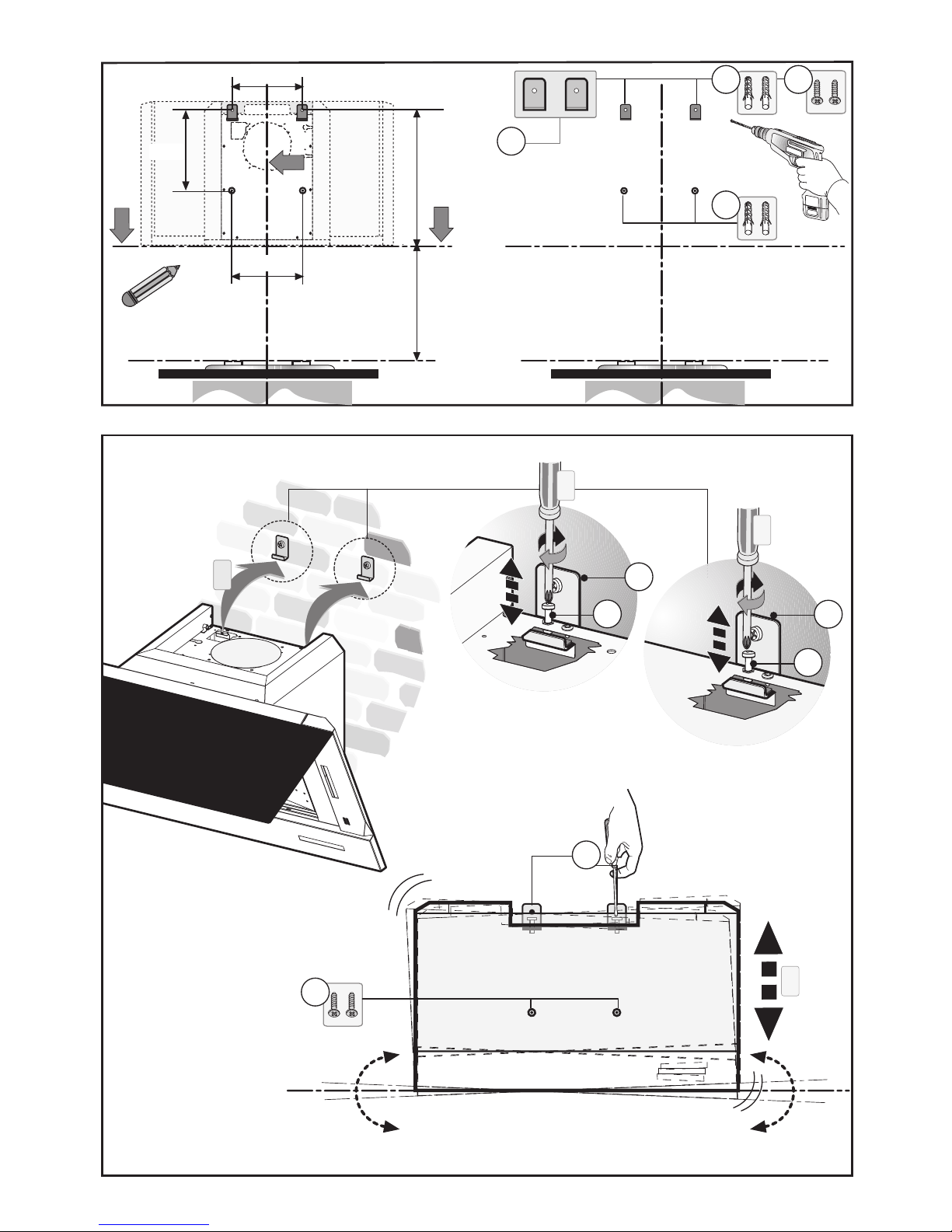
Wall mounting
Trace the bottom side of the hood on the wall. Consider the
measurements shown in g. 3 and minimum distance from
the cooking surface.
- Mark and drill the holes, following the measurements
shown in g. 3.
- Fasten the 4 anchors Ag. 3.
- Fasten the 2 brackets Cto the wall using the 2 screws B
g. 3.
- Make sure the 2 levelling screws Dare not tight (g. 4).
- Take the appliance and hang it on the 2 brackets Cgure
4 - phase 1.
- Align the appliance horizontally using the two levelling
screws Dgure 4 - phase 2.
- Once the adjustment has been made, fasten the hood
permanently using the screws Bgure 4- phase 3.
- When carrying out the xing operations, use only screws
and screw anchors suited to the type of wall (e.g. reinforced
concrete, plasterboard etc.).
If the screws and screw anchors are supplied with the
appliance, make sure that they are suited to the type of wall
to which the hood must be xed.
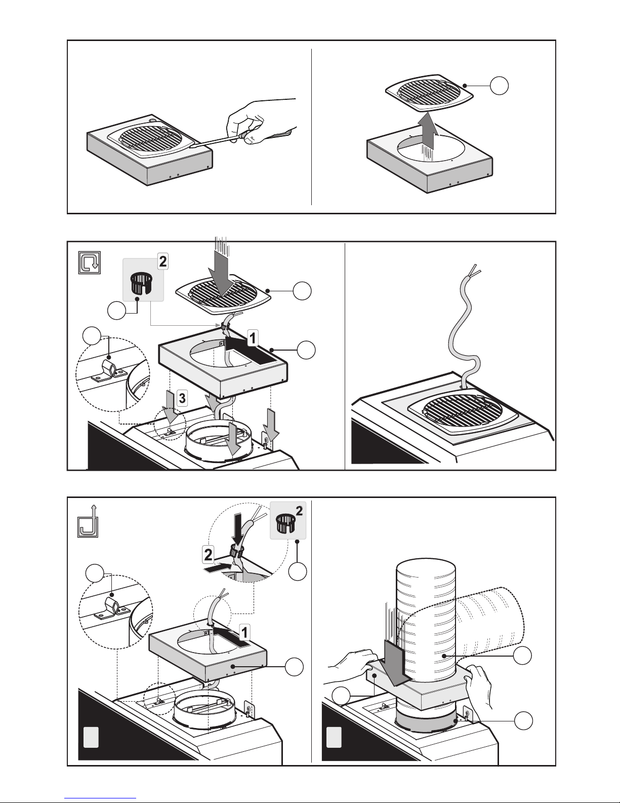
• Installation of models without decorative ducts
- Extractor hood
- Unclip the canopy Mand remove the grille E(Fig. 5).
- Pass the power supply cable through the slot in the canopy
M, as indicated in Fig. 7A.
- Taking the grommet H, position it between the power cable
and the slot Fig. 7A.
- Connect the exible hose L(not supplied) to the hood, so
that it is aligned with the air exhaust outlet.
If the air exhaust is on top, use Fig. 7 as a guide; otherwise,
if it is at the rear, use Fig. 8 as a guide.
- Secure the fairing M, taking care to ensure that it is correctly
hooked on the securing pins.
- Filtering version
- Unhook the small cupola Mand remove the grille E(Fig. 5).
- Pass the power supply cable through the slots of the small
cupola Mas shown in Fig. 6.
- Take the fairlead Hand position it between the power
supply cable and the slot.
- Fasten the small cupola Mand the grille Emaking sure that
is it perfectly hooked on to the fastening pins G. (Fig. 6).
- If you find a bracket such as the one indicated in Fig.9A or
Fig.10B included in the product packaging, this should be
fixed to the hood using the supplied screws.
- Take the activated charcoal lters and position them in the
specic brackets, as shown in gure 9or 10.
• Optional accessories
This model may have decorative ducts as optional accessories
- ask your retailer for information.
Before installing decorative ues it is necessary to remove the
small cupola and loosen the 4 screws Bthat lock the fastening
pins Gas shown in Fig.12.
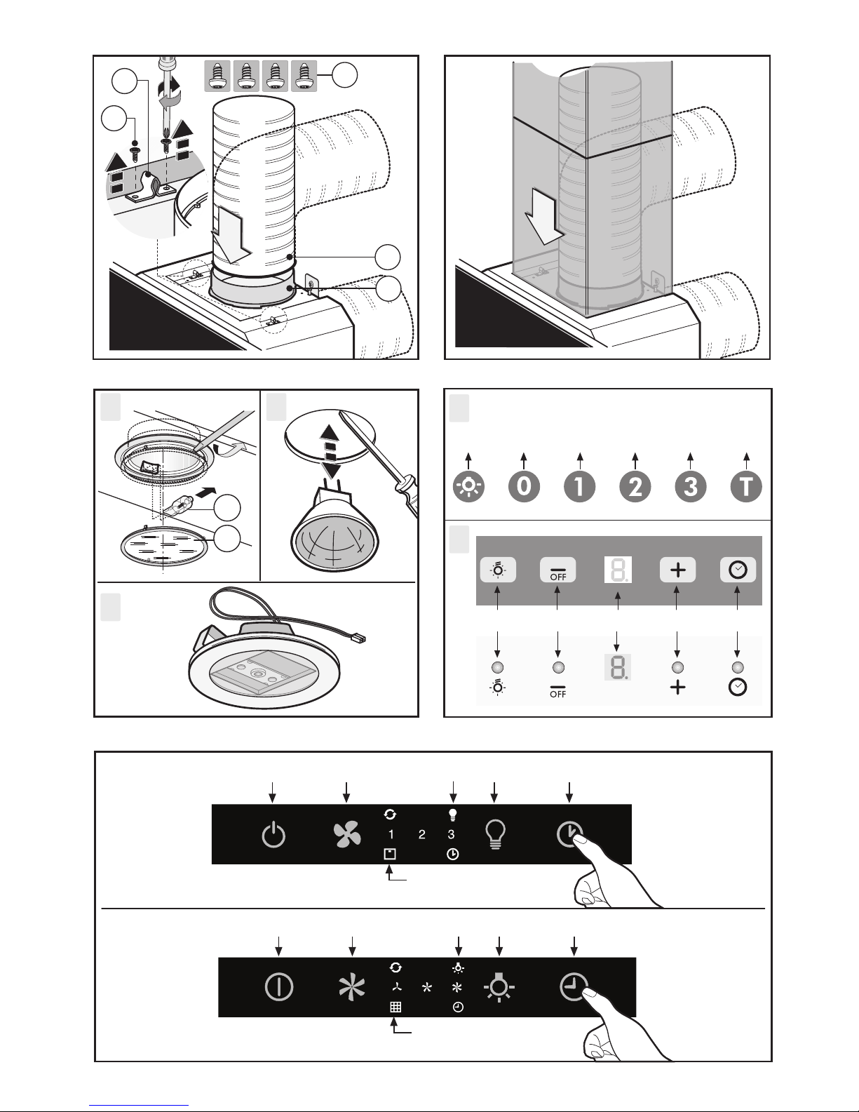
• Installation of models with decorative ducts - extractor
hood
Make sure the electrical power supply is within the
measurements of the decorative connector.
Adjust the width of the support bracket of the top connector
(Fig. 11).
Then x it to the ceiling so that it is on the same axis as the
hood using screws Aand observing the distance from the
ceiling shown in (Fig. 11). Connect ange Fto the air exhaust
hole using exible hose L(Fig.12).
Slide the top connector inside the lower duct and place this
on the body (Fig. 13).
Pull out the top duct as far as the bracket and secure it using
screws B(Fig. 11).
To transform the hood from a ducting version into a ltering
version, ask your dealer for the charcoal lters and follow the
installation instructions.
• Recirculation version
Please note:
In order to transform the hood from a extractor hood into
cooker hood the carbon lters must be ordered at your
retailer as accessory.
We have two different types of Kit, one with extractable
carbon filters (Fig.9) and the other one with re-usable carbon
- 10 -

filters (washable). (Fig.10).
Unlike traditional carbon lters, this carbon lter can be
washed and reactivated for approximately 12-15 times.
With normal hood use, this lter should be cleaned once
every 2-3 months. The lter can be washed into a dishwasher
at the highest temperature using a standard dishwasher
detergent.
After washing, dry the lter in the oven at 100° C for 10-15
minutes to reactivate it.
The lter will retain its odour-absorbing capacity for three
years, after which it will have to be replaced.
- To replace the extractable active carbon filters X, pull lever
outwards as shown in Fig.9
- To replace re-usable carbon filters Y, remove the brackets
from their seat, pulling them outwards (Fig.10).
- If you find a bracket such as the one indicated in Fig.9A or
Fig.10B included in the product packaging, this should be
fixed to the hood using the supplied screws.
• Optional
- It is possible to request an appliance with the “courtesy
lights” function.
USE AND MAINTENANCE
•We recommend that the cooker hood is switched on before
any food is cooked. We also recommend that the appliance
is left running for 15 minutes after the food is cooked, in
order to thoroughly eliminate all contaminated air.
The eective performance of the cooker hood depends on
constant maintenance; the anti-grease lter and the active
carbon lter both require special attention.
• The anti-grease lter is used to trap any grease particles
suspended in the air, therefore is subject to saturation (the
time it takes for the lter to become saturated depends on
the way in which the appliance is used).
- To prevent potential re hazards, the anti-grease lters
should be washed a minimum of every 2 months (it is
possible to use the dishwasher for this task).
- After a few washes, the colour of the lters may change.
This does not mean they have to be replaced.
If the replacement and washing instructions are not
followed, the anti-grease lters may present a re hazard.
• The active carbon lters are used to purify the air which
is released back into the room. The lters are not washable
or re-usable and must be replaced at least once every four
months. The active carbon lter saturation level depends
on the frequency with which the appliance is used, the
type of cooking performed and the regularity with which
the anti-grease lters are cleaned.
• Clean the cooker hood frequently, both inside and outside,
using a cloth which has been dampened with denatured
alcohol or neutral, non-abrasive liquid detergents.
• The light on the cooker hood is designed for use during
cooking and not for general room illumination. Extended
use of the light reduces the average duration of the bulb.
• If the appliance is equipped with COURTESY LIGHTS it is
possible to use them for general room lighting for a prolonged
amount of time.
• Replacing halogen light bulbs (Fig. 14A).
To replace the halogen light bulbs B, remove the glass pane
C using a lever action on the relevant cracks.
Replace the bulbs with new ones of the same type.
Caution: do not touch the light bulb with bare hands.
• Replacing dichroic lamps (Fig. 14B).
In order to replace the dichroic lamps, carefully remove
the lamp from the lamp holder with the help of a small at
screwdriver or a similar tool. PLEASE NOTE! In doing this
operation, please take care not to scratch the hood.
Replace the bulbs with new ones of the same type.
• Replacing LED lamps (Fig.14C).
If the appliance version is with LED lamps, the intervention of
a specialised technician is necessary to replace them.
• Commands: Luminous (Fig.15A) the key symbols are ex-
plained below:
A= LIGHT
B= OFF
C= SPEED I
D = SPEED II
E= SPEED III
F = AUTOMATIC STOP TIMER - 15 minutes (*)
•If your appliance is equipped with the BOOSTER speed
function, start from level THREE speed and keeping the button E
pressed for about 2 seconds, this function activates for about 10
minutes after which it goes back to the previously set speed.
WhenthefunctionisactivetheLEDashes.Tointerruptitbefore
the 10 minutes have expired press key E again.
•By pressing key F fortwo seconds(withthehoodswitchedo)
the “clean air” function is activated. This function switches the
appliance on for ten minutes every hour at the rst speed. As
soon as this function is activated the motor starts up at the rst
speed for ten minutes, During this time key F and key C must
ash at the same time.
After ten minutes the motor switches o and the LED of key F
remains switched on with a xed light until the motor starts up
again at the rst speed after fty minutes and keys F and C start
to ash again for ten minutes and so on.
Bypressinganykeyforthe exclusionof thehoodlightthehood
will return immediately to its normal functioning (e.g. if key D is
pressed the “clean air” function is deactivated and the motor
moves to the 2nd speed straight away. By pressing key B the
function is deactivated).
(*) The “automatic stop timer” delays stopping of the hood,
which will continue functioning for 15 minutes at the operating
speed set at the time this function is activated.
• Active carbon/grease lter saturation:
- When button Aashes at a frequency of 2seconds, the grease
lters must be cleaned.
- When button Aashes at a frequency of 0.5 seconds, the
carbon lters must be replaced.
After the clean lter has been replaced, the electronic memory
must be reset by pressing button Afor approximately 5
seconds, until the light on the button stops ashing.
Commands: (Fig.15B)
Push-button A = on/o lights switch
Push-button B = switches the motor on/o. The appliance
switches on at speed level 1, If the cooker hood is on depress
the push-button for 2 sec. to switch o the cooker hood. If the
cookerhoodisatspeedlevel1itwillnotbenecessarytodepress
the push-button to switch the cooker hood o. Decreases the
motor speed.
Display C = indicates the motor speed level selected and
activates the timer.
Push-button D = switches the motor on. Increases the motor
speed. Touching the key at 3rd speed, the intensive function
- 11 -

runs for 10’, then the appliance go back to work at the original
speed. During this function the display blinks.
Key E = The Timer times the functions on activation for
15 minutes, after which they are switched o. The Timer is
deactivated by re-pressing Key E. When the Timer is activated
the decimal point must ash on the display. The Timer cannot
be activated if the intensive speed is functioning.
The “clean air” function is activated by pressing key Efor 2
seconds when the appliance is switched o. This switches
the motor on for 10 minutes every hour at the rst speed.
During functioning a rotary movement of the peripheral
segments must be visualised on the display. When this time
has passed the motor switches o and the xed letter “C”
must be visualised on the display until the motor re-starts
after 50 minutes for another 10 minutes and so on. Press any
key apart from the light keys to return to normal functioning.
Press key Eto deactivate the function.
• Active carbon/grease lter saturation:
- When display item Cashes, at a speed where it alternates
with the letter F(e.g. 1 and F), the grease lters must be
washed.
- When display item Cashes, at a speed where it alternates
with the letter A(e.g. 1 and A), the carbon lters must be
replaced.
After the clean filter has been positioned correctly, the
electronic memory must be reset by pressing button A
for approximately 5 seconds, until the indication For
tshown on the display Cstops ashing.
• Commands: (Fig.16)
NOTE: With this control it is possible to manage the appliance
also with a remote control to be requested as accessory.
Power Button (A) =The button only switches on the MOTOR
and not the LIGHTS. If the motor and the lights are on then the
button switches o the entire hood (MOTOR - LIGHTS).
By pressing the button the motor starts at 1st speed.
Fan speed Button (B)= From the OFF position, press once for
speed 1, twice for the speed 2, and three times for the speed
3. In order to engage the booster speed, press the button for
5 sec., no matter what status the hood is currently in (except
for switched o). For each speed only the led indicating the
set speed will turn on. The intensive speed is indicated by
the ashing of the led indicating speed 3. The duration of the
intensive speed is 10 minutes; after this time the hood goes
back to the last set speed.
In order to remove the intensive speed press the power button
and the hood will switch o, or press the Fan speed button
and the speed goes back to the previously set one. Speed of
the hood with cyclic trend.
Light button (C)= There are three light levels: High, medium,
low.
From the o position press once for the high level, twice for
the medium level, three times for the low level and four times
to turn the lights o.
The level of the lights has a cyclic trend: High, medium,
low, o.
ATTENTION! This function is only available with halogen
lamps and NOT with LED lamps.
Timer button (D) = With any type of speed (excluding the
intensive speed), by pressing the button, the timer function
is activated for 15 minutes. After this time has elapsed the
hood will turn o (motor and any light on).
If the product purchased is equipped with optional features
such as the courtesy lights or side spotlights, keep the Timer
button pressed for 4 seconds to turn them on. Complete the
same operation to turn them o.
Lights indicator (E) =The lights indicator will switch on when
the lights are on at any level.
Antigrease/Active charcoal lter Saturation Warning
light (F):
After 30 hours of operation the LED of the lters warning
light switches on without flashing. This means that the
antigrease lters will have to be washed.
In order to switch o the LED is it necessary to reset the
function by pressing the fan speed button (B) for about 5
seconds while the hood is switched o. Once this operation
is complete the setting is reset to zero.
After 120 hours of operation the LED of the lters warning
light switches on and ashes. This means that the active
charcoal lters need to be replaced.
If your model is the suction version, it is sucient to reset
the function.
In order to switch o the LED is it necessary to reset the
function by pressing the fan speed button (B) for about 5
seconds while the hood is switched o. Once this operation
is complete, the setting is reset to zero.
ATTENTION: If the product is equipped with regenerative
charcoal lters (washable) they do not need to be replaced,
just washed; refer to paragraph “1.1 lter version”.
Clean air warning light (G)= With the hood turned o,
pressing the Power button (A) for 5 sec. activates the clean
air function. This switches the motor on at the speed 1 for
10 min. each hour. The warning light turns on and ashes
and the speed 1 LED switches on. The remaining 50 min. the
warning light stays on. The function deactivates by pressing
any button except for the ones for the lights.
THE MANUFACTURER DECLINES ALL RESPONSIBILITY
FOR EVENTUAL DAMAGES CAUSED BY BREACHING THE
ABOVE WARNINGS.
- 12 -


3LIK0754
Table of contents
Other Caple Ventilation Hood manuals

Caple
Caple DD911BK User manual

Caple
Caple INCHP3 User manual

Caple
Caple AH600BK User manual

Caple
Caple BXC600SS User manual

Caple
Caple BXC611 User manual

Caple
Caple FSCHSS7 User manual

Caple
Caple Mi360 User manual

Caple
Caple CHIMNEY FGC900SS User manual

Caple
Caple F Series Chimney User manual

Caple
Caple CSB606 User manual
Popular Ventilation Hood manuals by other brands

ELICA
ELICA Allasio EAL336SS Use, care and installation guide

Chamberlain
Chamberlain CAPXSTK quick start guide

Electrolux
Electrolux Icon E36WC45FSS Specification sheet

Gorenje
Gorenje DVG 8340 E Instructions for use

Hanseatic
Hanseatic SY-103B3-P1-C81-L22-600 user manual

Sirius Range Hoods
Sirius Range Hoods SIU4 installation instructions