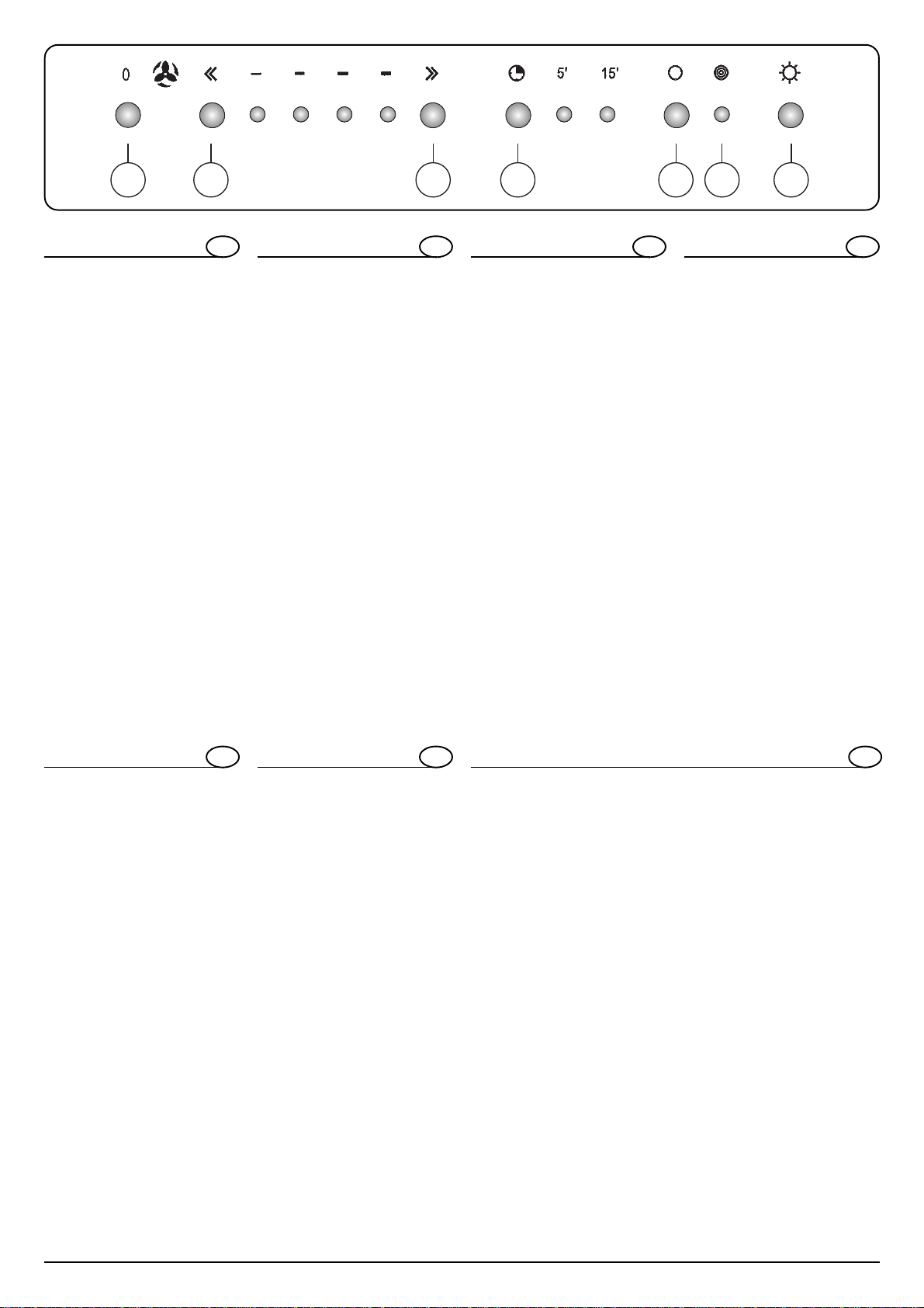
Caple J129 User manual

2J129
Fig.1
Fig.2

3J129
UTILIZZAZIONE
Lacappaèrealizzataperessereutilizzatainversioneaspiranteadeva-
cuazione esterna o filtrante a ricircolo interno.
VERSIONE ASPIRANTE EVACUAZIONE ESTERNA
Perpoterutilizzarequestafunzionemunirsidiuntuboflessibiledacolle-
gare al raccordo “A” fig1 che andrà successivamente fissato al soffitto.
VERSIONE FILTRANTE RICIRCOLO INTERNO
Quando non si ha la possibilità di evacuare l’aria all’esterno si utilizza
un filtro a carboni attivi.
L’ariavienedepuratadalfiltroerimessanell’ambiente attraverso legri-
glie presenti nei camini.
Perconvertirelacappada“Aspirante”a“Filtrante”,richiederealvendito-
re o alla ditta costruttrice il corredo di montaggio.
COLLEGAMENTO ELETTRICO
Prima di effettuare qualsiasi collegamento, assicurarsi che la tensione
di rete corrisponda alla tensione riportata sull’etichetta
caratteristiche,situataall’internodell’apparecchio.
Siconsiglia di delegare il collegamento elettrico adun tecnicoqualifica-
to.
APPARECCHIOPROVVISTO DI SPINA
Allacciarlo ad una presa conforme alle norme vigenti.
La spina una volta inserita nella presa, deve trovarsi in un punto facil-
menteaccessibile.
Se si intende allacciarlo direttamente alla rete elettrica togliere la spina
edapplicare uninterrutore bipolare anorme con una distanza deicon-
tatti in apertura non inferiore a 3mm.
APPARECCHIO SPROVVISTO DI SPINA
Applicare una spina a norme oppure un interruttore bipolare a norme
con una distanza dei contatti in apertura non inferiore a 3mm.
Sideclinaogniresponsabilitàperinconvenientiderivatidall’inosservan-
za delle suddette disposizioni.
L’APPARECCHIO IN CLASSE 1 DEVE ESSERE
COLLEGATO AD UN IMPIANTO DI TERRA.
L’allacciamento deve essere eseguito come segue:
MARRONE = L (linea)
BLU = N (neutro)
GIALLO/VERDE = (terra)
L’APPARECCHIO IN CLASSE 2 NON DEVE ESSERE
COLLEGATO AD UN IMPIANTO DI TERRA.
Per gli apparecchi in classe 2 ,recanti sulla etichetta caratteristiche il
doppio quadrato,l’allacciamento deve essere eseguito come segue:
MARRONE = L (linea)
BLU = N (neutro)
ISTRUZIONI PER IL MONTAGGIO
La cappa pesa circa 35 kg quindi è importante fissarla al soffitto con un
montaggio accurato.
L’apparecchio messo in opera dovrà distare dal piano di cottura non
meno di 60 cm nel caso di fornelli elettrici, e 65 cm nel caso di fornelli a
gas.
Se le istruzioni di installazione del dispositivo di cottura a gas speci-
ficano una distanza maggiore,bisogna tenerne conto.
Per installare la cappa ad una giusta altezza bisogna prima di tutto
regolare la lunghezza “L”della struttura telescopica.
Per fare questo procedere nel seguente modo:
1) misurare l’altezza “H” tra il soffitto ed il pavimento
2) stabilire la distanza desiderata “D”tra il pavimento e la cappa
3) misurare l’altezza “X”della cappa
4) si otterrà “L”applicando la seguente formula:
L=H-(D+X) fig1
Regolata la lunghezza della struttura telescopica fissare i due pezzi
fig2.
MANUTENZIONE
Disinserire l’apparecchio dalla rete elettrica prima di effettuare qual-
siasi operazione di manutenzione.
Ilbuonfunzionamentodellacappaècondizionatodall’assiduitàconcui
vengono effettuate le operazioni di manutenzione in modo particolare
delle griglie alluminio e del filtro al carbone attivo.
Le griglie hanno il compito di trattenere le particelle grasse o solide in
sospensionenell’aria.
Pertantosonosoggetteadintasarsiintempivariabiliasecondodell’uso
e del tipo di cucina .
Le griglie in alluminio stirato vanno lavate a mano o in lavastoviglie
,lasciandole asciugare prima del montaggio.
In caso di inadempienza delle istruzioni di lavaggio vi è la possibilità
di incendio.
Il filtro al carbone attivo ,presente solo nella versione filtrante ,ha la
funzione di trattenere gli odori e depurare l’aria.
La saturazione del filtro carbone si verifica dopo un uso più o meno
prolungato a secondo del tipo di cucina e della regolarità della pulizia
dellegrigliealluminio.
Sostituireil filtrocarbone,quando viene segnalatodalla spia led “F” (ver-
sioneelettronica).
Inognicasoquandononèsegnalato,sostituirelacartucciaalmassimo
ogni 4 mesi.
PULIZIA DELLA CAPPA
Per la pulizia esterna della cappa usare un panno inumidito con alcool
denaturato o detersivi liquidi neutri.Evitare l’uso di prodotti contenenti
abrasivi.
Pulire frequentemente tutti i depositi sul ventilatore e le altre superfici
con i medesimi prodotti.
ATTENZIONE: ISTRUZIONI PER LA SICUREZZA
L’evacuazionenondeveessereconvogliataneinuncaminofunzionan-
teperloscaricodeifumiodigascombustibili,neinuncondottoutilizza-
to come canna fumaria per ambienti in cui sono installati fonti con fuo-
chiaperti.Perincanalareivapori,devonoessererispettateledisposizio-
ni delle autorità competenti.In caso di funzionamento contemporaneo
dellacappaconevacuazioneesternaedialtrefonti necessitantidican-
na fumaria, ci si deve accertare che vi sia sufficiente apporto d’aria.
1) Non cercate di controllare i filtri con la cappa in azione.
2) Non ostruite le uscite di scarico dell’aria
3) Non toccare le lampadine o il copri-lampada dopo il protratto uso
dell’apparecchio
4) E ‘‘‘vietato cuocere cibi alla fiamma sotto la cappa.
5) Evitare la fiamma libera, perché dannosa per i filtri e pericolosa per
gli incendi.
6) Controllare costantemente la frittura per evitare che l’olio surriscal-
dato prenda fuoco.
7) Primadieffettuaremanutenzionidisinserirelacappadallareteelet-
trica.
8) Sideclinaogniresponsabilitàpereventualidanniprovacatidall’inos-
servanza delle suddette avvertenze.
I

4J129
DD
EINSATZMÖGLICHKEIT
Diese Dunstabzugshaube ist so konzipiert, dass sie sowohl im Abluft-
betrieb (Ansaugfunktion), als auch im Umluftbetrieb (Filterfunktion) ein-
gesetzt werden kann.
ABLUFTBETRIEB MIT ANSAUGFUNKTION
Zum Einsatz in dieser Version beschaffen Sie sich bitte ein Flexrohr, das
an den Anschluss „A“ (Abb.1) anzuschließen ist und anschließend an
der Decke befestigt werden muss.
ACHTUNG:
Bei gleichzeitigem Betrieb der Dunstabzugshaube im Abluftbetrieb
und Feuerstätten darf im Aufstellraum der Feuerstätte der Unter-
druck nicht höher als 4 Pa(4x10 –5 bar) sein.
UMLUFTBETRIEB MIT FILTERFUNKTION
Besteht keine Möglichkeit, die Luft ins Freie abzuleiten, muss ein Aktiv-
kohlefiltereingesetzt werden.
Die Luft wird gefiltert und über die im Schacht befindlichen Gitter gerei-
nigt wieder in den Raum zurückgeführt.
ZumUmrüsten derDunstabzugshaube von„Abluftbetrieb“ auf „Umluft-
betrieb“ fordern Sie bitte bei Ihrem Fachhändler oder beim Gerätehers-
teller den hierzu erforderlichen Montagesatz an.
ELEKTRISCHER ANSCHLUSS
VordemAnschlussmusssichergestelltwerden,dassdieNetzspannung
den auf dem Typenschild (im Geräteinnern) angegebenen Werten ent-
spricht.
Bitte lassen Sie den Elektroanschluss durch Fachpersonal durchführen.
MIT STECKER BESTÜCKTES GERÄT
SchließenSie das Gerät aneine den einschlägigen Bestimmungenent-
sprechende Steckdose an. Der angeschlossene Stecker sollte sich an
einer leicht zugänglichen Stelle befinden.
Solltedas Gerät direkt andas Stromnetz angeschlossen werden, ist der
Steckerzuentfernen,undeineTrennvorrichtungmittelseinesvorschrifts-
mäßigenzweipoligenSchaltersmiteinerKontaktöffnung,die3mmnicht
unterschreiten darf, zu installieren.
GERÄT OHNE STECKER
Versehen Sie das Gerät mit einem vorschriftsmäßigen Stecker oder ei-
nem zweipoligen Schalter mit einer Kontaktöffnung, die 3 mm nicht un-
terschreiten darf. Jegliche Haftung für Schäden, die durch Nichteinhal-
tung obiger Anweisungen auftreten, wird zurückgewiesen.
GERÄTE DER KLASSE 1 MÜSSEN AN EINEN
ERDLEITER ANGESCHLOSSEN WERDEN.
Der Anschluss ist wie folgt vorzunehmen:
BRAUN = L (Leitungsnetz)
BLAU = N (Nullleiter)
GELB/GRÜN = (Erde)
GERÄTE DER KLASSE 2 ERFORDERN KEINEN ERDANSCHLUSS.
Geräte der Klasse 2, auf deren Typenschild das Symbol eines Doppel-
vierecks abgebildet ist, sind wie folgt anzuschließen:
BRAUN = L (Leitungsnetz)
BLAU = N (Nullleiter)
MONTAGEANLEITUNG
Die Dunstabzugshaube wiegt ca. 35 kg, die Befestigung an der Decke
erfordert demnach größte Sorgfalt.
Beifertiginstalliertem Gerätmuss der Abstandüber demKochfeldmin-
destens 60 cm betragen, wenn es sich um elektrische Kochfelder han-
delt, und mindestens 65 cm, wenn es sich um Gas-Kochfelder handelt.
Sollten die Installationsanweisungen der Gas-Kochvorrichtungen ei-
nen größeren Abstand vorschreiben, ist dieser zu beachten.
Um bei der Installation auch die richtige Höhe zu ermitteln, ist in erster
Linie die Länge „L“ des Teleskopschachtes zu regulieren.
Zur Ermittlung dieser verfahren Sie wie folgt:
1) Messen Sie die Höhe „H“ d.h. den Abstand zwischen Decke und
Fußboden.
2) Bestimmen Sie den gewünschten Abstand „D“ zwischen Fußboden
und Dunstabzugshaube.
3) Messen Sie die Höhe „X“ der Dunstabzugshaube.
4) Sie erhalten den Wert „L“ mittels folgender Formel:
L=H-(D+X) Abb.1
Wurde der Teleskopschacht auf die korrekte Länge eingestellt, sind bei-
de Teile (Abb.2) zu befestigen.
WARTUNG UNF PFLEGE
Vor jeder Wartung und Pflege muss das Gerät vom Stromnetz ge-
trennt werden.
NureineregelmäßigeWartungund PflegegarantierteineguteLeistung
desGerätes. Besondere Pflege ist den Alugittern unddem Aktivkohlefil-
ter zuzuwenden.
DieGitterdienenzurAufnahmederinderLuftschwebendenFettpartikel.
Sie sind der Verschmutzung besonders ausgesetzt und sollten, je nach
Gebrauch und Kochgewohnheiten in mehr oder weniger langen Zeit-
abschnitten gereinigt werden.
DieGitteraus gezogenem Aluminium sindvonHandoderimGeschirr-
spüler zu reinigen. Lassen Sie sie vor erneuter Montage gut trocknen.
Durch Nichtbeachtung dieser Hinweise kann Brand verursacht wer-
den.
DerAktivkohlefilter (erforderlich nurbei Umluftbetrieb) dientzur Aufnah-
me der Gerüche und Reinigung der Luft.
DieSättigung diesesFilters hängt vom Gebrauch, der Art der gekochten
SpeisenunddermehroderwenigerhäufigenReinigungderMetallfilterab.
Ermussausgetauschtwerden,wenndurchdieKontrollleuchte„F“(elek-
tronische Version) die Sättigung desselben signalisiert wird.
AufjedenFalljedochsollteeralle4Monateausgetauschtwerden,auch
wenn kein Sättigungssignal aufleuchtet.
REINIGUNG
ZurReinigungderäußerenTeileverwendenSiebittenureinmitdenatu-
riertemAlkoholoder einemmildenSpülmittel angefeuchtetesTuch.Ver-
meiden Sie Reiniger, die Scheuermittel enthalten.
Schmutzablagerungen auf dem Gebläse sind öfter zu entfernen, ver-
wenden Sie auch hierzu, wie auch für die übrigen Oberflächen, diesel-
benmildenReinigungsmittel.
ACHTUNG: SICHERHEITSANWEISUNGEN
DieAbluftdarfwederineinenSchornstein,derbereitszurAbleitungvon
Verbrennungsgasen oder Rauch verwendet wird, noch in einen Ab-
luftschacht, der für Räume mit offenen Feuerstätten dient, geleitet wer-
den. Hinsichtlich der Ableitung der Kochdünste sind die behördlichen
Vorschriftenzubeachten.BeigleichzeitigemBetriebeinerDunstabzugs-
haube im Abluftbetrieb und anderer raumluft- und kaminabhängigen
Feuerstättenmusssichergestelltwerden,dasseineausreichendeBelüf-
tung gewährleistet ist.
1) VersuchenSienichtdieFilter zuüberprüfen,wenn sich dieDunstab-
zugshaube in Betrieb befindet.
2) Die Belüftungsöffnungen dürfen nicht abgedeckt werden.
3) BerührenSiewederdieLampennochdieLampenabdeckung,wenn
das Gerät schon längere Zeit eingeschaltet ist.
4) FlambierenSienieunter der Dunstabzugshaube,diesistgefährlich.
5) VermeidenSieoffeneFlammen,dieseschaden den Filternundkön-
nen einen Brand auslösen.
6) Speisefett kann in wenigen Minuten überhitzen und sich selbst ent-
zünden.LassenSiedemnachPfannenundFritteusenniemalsunbe-
aufsichtigt.
7) Schalten Sie die Dunstabzugshaube vor der Reinigung vom Strom-
netz ab.
8) JeglicheHaftung fürSchäden, diedurch Nichteinhaltungobiger An-
weisungen auftreten, wird zurückgewiesen.

5J129
GB
USE
The hood is designed to be used either to filter and re-circulate air or in
a ducted vented mode.
OUTDOOR VENTED INSTALLATION
To use the hood in the vented mode, you need to connect a flexible
pipe to the connector “A” (fig. 1), which should then be fastened to
the ceiling.
VENTLESS FILTERING INSTALLATION
Whentheaircannotbeventedtotheoutside,thehoodcanbefittedwith
an activated carbon filter.
The air is purified by the filter and re-circulated into the room via the
grids on the flues.
To switch from “Vented” to “Ventless” operation, contact your retailer or
the manufacturer for the relevant assembly kit.
ELECTRICAL CONNECTION
Beforemaking any electrical connections, make sure that thevoltage of
theelectricalmainscorrespondswiththevalueindicatedontheappliance
rating sticker.
It is highly recommended that the electrical connection be made by a
qualifiedelectrician.
APPLIANCE FITTED WITH A PLUG
Insert the plug into a socket that complies with the applicable norms in
force.
Once plugged into the socket, the plug must be easily accessible.
Ifyou intend to connect the hood directly to the electrical mains, remove
the plug and add a standard bipolar switch with a minimum contact
opening of 3mm.
APPLIANCE NOT FITTED WITH A PLUG
Fit a standard plug or a standard bipolar switch compliant with the
applicable norms in force, with a minimum contact opening of 3mm.
The manufacturer will not be held responsible for any problems arising
from failure to comply with the above instructions.
CLASS 1 APPLIANCES MUST BE EARTHED
The connection must be made as follows:
BROWN = L (current)
BLUE = N (neutral)
YELLOW/GREEN= (earth)
CLASS 2 APPLIANCES DO NOT HAVE TO BE EARTHED
Class 2 appliances labelled with a rating sticker featuring the symbol in
the form of a double square must be connected as follows:
BROWN = L (current)
BLUE = N (neutral)
ASSEMBLY INSTRUCTIONS
Thehoodweighsapproximately35kgandshouldthereforebefastened
securely to the ceiling.
The appliance should be installed at least 60 cm above an electric hob
and at least 65 cm above gas hobs.
If the appliance is installed above a gas cooking device with
installationinstructions specifying a greaterclearance, you must take
this into account.
To install the hood at the correct height, first adjust the length “L” of the
telescopic flue.
To do so, proceed as follows:
1) measure the height “H” from the ceiling to the floor
2) fix the desired distance “D” between the hood and the floor
3) measure the height “X” of the hood
4) to find out “L”, apply the following formula:
L=H-(D+X) fig. 1
Once you have adjusted the length of the telescopic flue, fasten the two
units (fig. 2)
MAINTENANCE
Disconnect the appliance from the electrical power supply before
performing any maintenance operations on the same.
The correct operation of the hood is directly related to how often it is
cleanedand serviced,especially the aluminium grids and the activated
carbon filter.
The grids trap any grease particles and solids suspended in the air.
Theythereforetend toclogover time,dependingon howoftenthe hood
is used and on the type of cooker installed.
The forged aluminium grids should be washed by hand or in your
dishwasher, and allowed to dry thoroughly before remounting.
Failure to comply with the washing instructions could result in a fire
hazard.
The activated carbon filterisonlyusedbytheventless,filteringversion,
and is designed to trap odours and clean the air.
The carbon filter is saturated after a varying amount of time depending
on the type of cooker used and on how regularly the aluminium grids
arecleaned.
Replace the carbon filter when prompted to do so by the LED indicator
light “F” (electronic version).
In any case, in the absence of such prompting, the cartridge must be
replaced at least once every four months.
CLEANING THE HOOD
Wipe the exterior of the hood with a cloth dampened with denatured
alcohol or mild liquid detergents. Avoid using abrasive products.
Wipe off all deposits from the fan and other hood surfaces frequently,
using the above products.
ATTENTION: SAFETY WARNINGS
The cooking vapours must not be vented to the outside along a flue
used for venting combustion fumes or gases, nor along a duct used as
aflueforroomsinwhichopenflameappliancesareinstalled.Thevapour
ducting installation must comply with the applicable norms in force. If
thehood is being used inthe outdoor vented mode whereother vented
fuel-burningappliancesareinstalled,youmustensurethereisasufficient
supply of air to the room.
1) Do not attempt to check the filters when the hood is in operation.
2) Do not obstruct any air outlets.
3) Do not touch the lamps or lamp diffusers after prolonged use of the
hood.
4) Do not flambé food underneath the hood.
5) Avoid leaving an open flame uncovered, as it could damage the
filters and increase the risk of fire.
6) Never leave frying food unattended to prevent hot oil from catching
fire.
7) Disconnectthehoodfromtheelectricalmainsbeforeperformingany
maintenanceoperations.
8) The manufacturer will not be held responsible for any damage
caused due to failure to comply with the above warnings.
GB

6J129
E
USO
La campana se fabrica para ser utilizada en la versión aspirante con
evacuación externa o filtrante con recirculación interna.
VERSIÓN ASPIRANTE CON EVACUACIÓN EXTERNA
Parapoderutilizarestafunciónsedebecontarconuntuboflexiblequese
va a conectar a la unión “A” fig.1 que posteriormente se fijará al techo.
VERSIÓN FILTRANTE CON RECIRCULACIÓN INTERNA
Cuando no existe la posibilidad de evacuar el aire hacia el exterior, se
utiliza un filtro de carbón activo.
Elaire es depurado por el filtroy se vuelve a introducir enel ambiente a
través de las rejillas presentes en las chimeneas.
Paraconvertir lacampana de “Aspirante”a “Filtrante”, soliciteal vende-
dor o a la empresa fabricante el equipo de montaje.
CONEXIÓN ELÉCTRICA
Antesde efectuar cualquier conexión, verifique que la tensión de la red
se corresponda con la tensión que se encuentra en la etiqueta de ca-
racterísticas ubicada en el interior del aparato.
Es aconsejable delegar la conexión eléctrica a un técnico especializa-
do.
APARATO PROVISTO DE ENCHUFE
Conéctelo a una toma de corriente conforme con las normas vigentes.
El enchufe una vez introducido en la toma, se debe encontrar en un
punto fácilmente accesible.
Si se pretende conectarlo directamente a la red eléctrica, quite el en-
chufe y aplique un interruptor bipolar conforme con las normas y con
una distancia entre los contactos de 3 mm. o mayor.
APARATO NO PROVISTO DE ENCHUFE
Aplique un enchufe conforme con las normas o un interruptor bipolar
tambiénconformeconlasnormasyconuna distancia entreloscontac-
tos de 3mm. o mayor.
Sedeclina toda responsabilidad por losinconvenientes que se puedan
producir derivados de la falta de respeto de las mencionadas disposi-
ciones.
EL APARATO DE CLASE 1 SE DEBE CONECTAR A TIERRA.
La conexión se debe realizar del siguiente modo:
MARRÓN = L (línea)
AZUL = N (neutro)
AMARILLO/VERDE= (tierra)
EL APARATO DE CLASE 2 NO SE DEBE CONECTAR A TIERRA.
Paralosaparatos declase 2, queposean enlaetiqueta decaracterísti-
caseldoblecuadrado,laconexiónsedeberealizardelsiguientemodo:
MARRÓN = L (línea)
AZUL = N (neutro)
INSTRUCCIONES PARA EL MONTAJE
Lacampanapesaaproximadamente35kg.,porlotanto,esimportante
fijarla al techo con un montaje cuidadoso.
Una vez instalada, la distancia entre el aparato y la superficie de coc-
ción no debe ser inferior a 60 cm. en el caso de quemadores eléctricos
y a 65 cm. en el caso de quemadores a gas.
Si las instrucciones de instalación del dispositivo de cocción a gas
especifican una distancia mayor, no hay que ignorarlo.
Para instalar la campana a una altura justa, es necesario, antes que
nada, regular la longitud “L” de la estructura telescópica.
Para hacerlo, proceda del siguiente modo:
1) mida la altura “H” entre el techo y el piso.
2) establezca la distancia deseada “D” entre el piso y la campana
3) mida la altura “X” de la campana
4) se obtendrá “L” aplicando la siguiente fórmula:
L=H-(D+X) fig1
Una vez regulada la longitud de la estructura telescópica, fije las dos
piezas (fig. 2)
MANTENIMIENTO
Desconecte el aparato de la red eléctrica antes de efectuar cual-
quier operación de mantenimiento.
El buen funcionamiento de la campana depende de la asiduidad con
queseefectúanlasoperacionesdemantenimiento,enparticulardelas
rejillas de aluminio y del filtro de carbón activo.
Las rejillas tienen la función de retener las partículas grasas o sólidas
que se encuentran en suspensión en el aire.
Por lo tanto, se pueden atascar en tiempos variables según el uso y el
tipo de cocina.
Las rejillas de aluminio estirado se deben lavar a mano o en lavavajilla
dejándolas secar antes de su montaje.
En caso de incumplimiento de las instrucciones de lavado, existe la
posibilidad de que se produzca un incendio.
El filtro de carbón activo, presente sólo en la versión filtrante, tiene la
función de retener los olores y depurar el aire.
La saturación del filtro de carbón se produce después de un uso más o
menos prolongado según el tipo de cocina y la regularidad de la lim-
pieza de las rejillas de aluminio.
Sustituya el filtro de carbón cuando lo indique la luz testigo “F” (versión
electrónica).
De todos modos, aún cuando no lo indique, sustituya el cartucho cada
4 meses como máximo.
LIMPIEZA DE LA CAMPANA
Para la limpieza externa de la campana use un paño humedecido con
alcoholdesnaturalizadoocondetergenteslíquidosneutros.Eviteeluso
de productos que contengan abrasivos.
Limpiefrecuentemente todos losdepósitos quese formanen elventila-
dor y en otras superficies con los mismos productos.
ATENCIÓN: INSTRUCCIONES PARA LA SEGURIDAD
Enambientes enlos cualeshay instaladasfuentes confuegos abiertos,
la evacuación no debe ser enviada a una chimenea para la descarga
dehumosodegasescombustibles,nihaciaunconductoutilizadocomo
conducto de humos. Para canalizar los vapores, se deben respetar las
disposiciones de las autoridades competentes. En caso de funciona-
miento simultáneo de la campana con evacuación externa y de otras
fuentes que necesitan conducto de humos, se debe verificar que haya
el suficiente aporte de aire.
1) No intente controlar los filtros con la campana en funcionamiento.
2) No obstruya las salidas de aire.
3) No toque las bombillas o el cubrelámpara después de un
prolongado uso del aparato.
4) Está prohibido cocinar alimentos con llama directa debajo de la
campana.
5) Evitelallamalibreyaquedañalosfiltrosypuedeproducirincendios.
6) Controle constantemente la fritura para evitar que el aceite
sobrecalentado se prenda fuego.
7) Antes de efectuar operaciones de mantenimiento, desconecte la
campana de la red eléctrica.
8) Se declina toda responsabilidad por los posibles daños que se
puedanproducirderivadosdelafaltaderespetodelasmencionadas
advertencias.
Table of contents
Other Caple Ventilation Hood manuals

Caple
Caple SIR900 User manual

Caple
Caple Storm ST524 User manual

Caple
Caple BUCH User manual

Caple
Caple BXI911 User manual

Caple
Caple CCH600BK Manual

Caple
Caple ZRC900 User manual

Caple
Caple BODY/DD600BK User manual

Caple
Caple DD810BK User manual

Caple
Caple GC100SS User manual

Caple
Caple Zi900SS Technical manual
Popular Ventilation Hood manuals by other brands

Gorenje
Gorenje S3 IHGC963S4X manual

KOBE
KOBE ISX2136SQB-1 Installation instructions and operation manual

U.S. Products
U.S. Products ADVANTAGE-100H Information & operating instructions

Kuppersberg
Kuppersberg DUDL 4 LX Technical Passport

Framtid
Framtid HW280 manual

Thermador
Thermador HGEW 36 FS installation manual