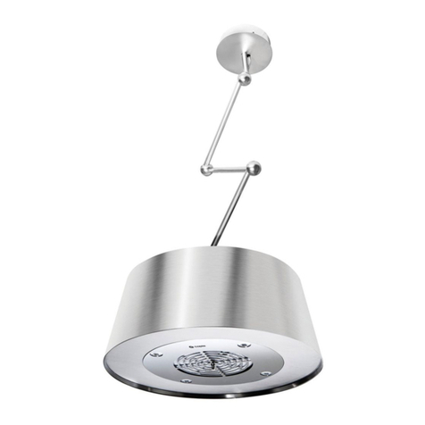
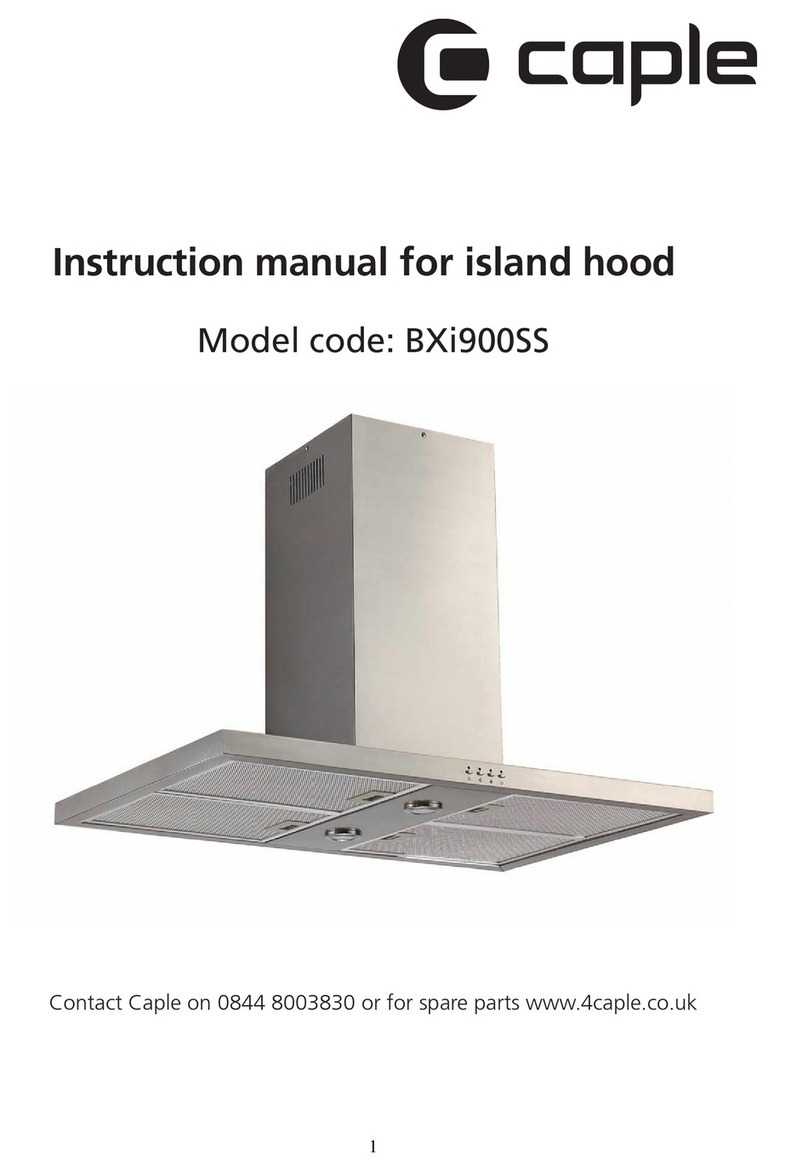
Caple Tela TEL900 User manual

Contact Caple on 0117 938 7420 for spare parts or www.caple.co.uk
Tela Island Hood
Instruction Manual
TEL900

2Instruction manual TEL900 Please keep this instruction manual for future reference
CONTENTS
Safety Instructions 3
Environmental Protection 7
Installation 9
TEL900/SHELF 20
Maximum Load 37
Control Panel 38
Timing 39
Lighting 40
Cleaning and Maintenance 41
After Sales 44
Caple Contact Details 48

3Instruction manual TEL900Please keep this instruction manual for future reference
SAFETY INSTRUCTIONS
WARNING
-The cooking surface and the inferior part of the cooker
hood must be at a minimum distance of 65 cm.
-The appliance is not intended for use by young children
or infirm persons without supervision. Young children
should be supervised to ensure they do not play with
the appliance.
-The cooker hood, when evacuating the extracted air,
could generate negative pressure in the room, which
can’t exceed the limit of 0.04 mbar, in order to avoid
the suck of exhausts deriving from the heat-source.
Therefore the room should be provided with air-intakes
to allow a constant flow of fresh air.
-When performing the electrical connections on the
appliance, please make sure that the current tap is
provided with earth connection and that voltage values
correspond to those indicated on the rating label
placed inside the appliance itself.
-Please disconnect the appliance from power mains,
before carrying out any cleaning or maintenance
operation. If the appliance is not equipped with a
nonseparable flexible cable and plug, or with another
device ensuring omnipolar disconnection from the
mains, with an opening distance between the contacts
of at least 3 mm, then such disconnecting devices must
be provided in the fixed installation.

4Instruction manual TEL900 Please keep this instruction manual for future reference
-If the appliance is equipped with a power cord and a
plug, it shall be placed in such a way that the plug can
be reached easily.
-The use of materials which can burst into flames
should be avoided in close proximity of the appliance.
When frying, please pay particular attention to fire
risk due to oil and grease. Being highly inflammable,
fried oil is especially dangerous. Do not use uncovered
electric grills. In order to avoid possible fire risk, all
instructions for grease-filter cleaning and for removing
eventual grease deposits should be strictly followed.
-Two persons are needed for the installation of
this product.
-This appliance complies with all relevant local and
national safety requirements. Inappropriate use can,
however, lead to personal injury and damage
to property.
-The cooker hood is not intended for outdoor use.
-It must only be used as a domestic appliance to extract
vapours and remove odours from cooking. Any other
usage is not supported by the manufacturer and could
be dangerous.
-Where a recirculation cooker hood is fitted above a gas
hob, please ensure that there is an adequate supply of
fresh air into the room in which it is installed. Please
seek the advice of a qualified gas fitter (e.g. GasSafe in
the UK) if necessary.

5Instruction manual TEL900Please keep this instruction manual for future reference
-Children under 8 years of age must be kept away from
the cooker hood unless they are constantly supervised.
-Children 8 years and older may only use the cooker
hood unsupervised if they have been shown how
to use it safely and recognise and understand the
consequences of incorrect operation.
-The electrical safety of this appliance can only be
guaranteed when correctly earthed. It is essential
that this standard safety requirement is met. If in any
doubt please have the electrical installation tested by a
qualified electrician.
-Do not connect the appliance to the mains electricity
supply by a multi-socket unit or an extension lead.
These are a fire hazard and do not guarantee the
required safety of the appliance.
-The cooker hood can get very hot during cooking due
to heat rising from the hob.
-Do not touch the housing or the grease filters until the
cooker hood has cooled down.

6Instruction manual TEL900 Please keep this instruction manual for future reference
APPROPRIATE USE:
-This appliance is intended to be used in household and
similar applications such as:
› Staff kitchen areas in shops, offices and other
working environments.
› Farm Houses.
› By clients in hotels, motels and other residential
type environments.
› Bed and breakfast type environments.

7Instruction manual TEL900Please keep this instruction manual for future reference
ENVIRONMENTAL PROTECTION
Waste electrical products should not be disposed of with household waste. Please recycle where
facilities exist. Check with your Local Authority or retailer for recycling advice. This appliance is
marked according to the European directive on Waste Electrical and Electronic Equipment (WEEE).
By ensuring this product is disposed of correctly, you will help prevent potential negative
consequences for the environment and human health, which could otherwise be caused by
inappropriate waste handling of this product. The symbol on the product indicates that this
product may not be treated as household waste. Instead it shall be handed over to the applicable
collection point for the recycling of electrical and electronic equipment. Disposal must be carried
out in accordance with local environmental regulations for waste disposal.
For more detailed information about treatment, recovery and recycling of this product, please
contact your local council, your household waste disposal service or the retailer where you
purchased the product.
WARRANTY
Your new appliance is covered by warranty. The warranty card is enclosed - if it is missing, you
must provide the following information to your retailer in order to receive a replacement: date of
purchase, model and serial number. Registration can also be completed online by visiting
www.caple.co.uk.
Ensure you keep your warranty card safe, you may need to show it to Caple Service together with
proof of purchase. If you fail to show your warranty card you will incur all repair charges.
Spare parts are only available from Caple Service and spare parts authorised centres.
CE DECLARATIONS OF CONFORMITY
This appliance has been manufactured to the strictest standards and complies with all applicable
legislation, Low Voltage Directive (LVD) and Electromagnetic Compatibility (EMC).

8Instruction manual TEL900 Please keep this instruction manual for future reference
UKCA DECLARATIONS OF CONFORMITY
This appliance has been manufactured to the strictest standards and complies with all
applicable legislation.
TECHNICAL FICHE
This appliance conforms to all current and applicable energy regulations. To view the Technical
Fiche that supports the energy labelling data, please visit the product page on our
website www.caple.co.uk.

9Instruction manual TEL900Please keep this instruction manual for future reference
INSTALLATION
This appliance can be used in recirculation mode only. In recirculation mode the air and fumes
conveyed by the appliance are cleaned by both a grease filter and an active charcoal filter, and
then released back into the room.
Prior to installation, make sure that the packaging is intact and all the parts are unbroken,
otherwise stop the installation and contact your retailer. The manufacturer is not responsible for
damages caused by material handling or product installation.
Before installing the appliance read all these instructions carefully.
WARNING:
This product must be installed by at least 2 people.
Start by removing the parts from the packaging and lay it on a suitable surface such as a soft
material such as sponge or fabric to protect the surface of the hood.
NOTE:
The following instructions are for installing the appliance only. If installing the appliance with
the TEL900/SHELF unit (sold separately), follow the installation instructions in ‘TEL900/SHELF’.

10 Instruction manual TEL900 Please keep this instruction manual for future reference
WHAT’S IN THE BOX
WHAT’S IN THE BOX
4.8 x 38 (x10) = BM4 x 25 (x4) = EØ8 (x10) = AM4 (x4) = F3.5 x 6.4 (x10) = DØ12 x 18 (x6) = G (x8) = O(x4) = L(x2) = M(x2) = N(x4) = Q(x2) = R(x2) = S
(
x1) = PM4 x 10 (x24) = H(x1) = X4 x 16 (x12) = I

11Instruction manual TEL900Please keep this instruction manual for future reference
Start by removing the product from the packaging and lay it on a suitable surface such as a soft
material to protect the surface of the hood.
1. Using the supplied drilling template (X), mark and drill the installation holes indicated by
the template.
1. (X)the installation 2.Make 10 x 8mm holes for the fixing plugs (A) using the following dimensions.Start by removing the product from the packaging and lay it on a suitable surface such as a soft material to protect the surface of the hood.
2. Make 10 x 8mm holes for the fixing plugs (A) using the following dimensions.

12 Instruction manual TEL900 Please keep this instruction manual for future reference
3. Fix the brackets (S) to the ceiling using the plugs (A) and screws (B) supplied.
4. Assemble the frame as shown in the following images.
4.Assemble the frame as shown in the following images.3. Fix the brackets (S) to the ceiling using the plugs (A) and screws (B) supplied.

13Instruction manual TEL900Please keep this instruction manual for future reference
>Add the clips as a further safety precaution to lock the cables in position (Fig.7).>Lift up the ceramic cover until youreachthe ceiling (Fig.10), make sure thatthe springs have hooked the ceramic cover. >Install the grease filter making sure to first install the hooks for the security steel cable (Fig.16).> Put the hood near the ceiling and hook the plate to the screws previously installed (Fig.8A). > Tighten the three screws fixing the plate to the ceiling, then lock the hood definitively byadding the security screw (Fig.9B). Connect the appliance to the electric grid. Fig.10.Fig.16.
>Add the clips as a further safety precaution to lock the cables in position (Fig.7).>Lift up the ceramic cover until youreachthe ceiling (Fig.10), make sure thatthe springs have hooked the ceramic cover. >Install the grease filter making sure to first install the hooks for the security steel cable (Fig.16).Fig.7.> Put the hood near the ceiling and hook the plate to the screws previously installed (Fig.8A). > Tighten the three screws fixing the plate to the ceiling, then lock the hood definitively byadding the security screw (Fig.9B). Connect the appliance to the electric grid. Fig.10.Fig.16.

14 Instruction manual TEL900 Please keep this instruction manual for future reference
> The grease filter must be positioned by orienting the dedicated opening near the speed indicator (Fig.17). In case the ceramic cover of the bodyis not perfectly flat or parallel to the body, it is possible to make an adjustment after installation. >Remove the grease filter. Using a Phillips screwdriver, (Fig.13A) tighten or loosen the three screws in order to raise or lower the ceramic body on aspecific side (Fig.14). After the adjustment insert the rubber tips and the grease filter again. Fig.14.Fig.13.Fig.17.
5. Thread the power cable through the frame, then place the frame onto thehood.
5. Thread the power cable through the frame, then place the frame onto the hood.

15Instruction manual TEL900Please keep this instruction manual for future reference
> The grease filter must be positioned by orienting the dedicated opening near the speed indicator (Fig.17). In case the ceramic cover of the bodyis not perfectly flat or parallel to the body, it is possible to make an adjustment after installation. >Remove the grease filter. Using a Phillips screwdriver, (Fig.13A) tighten or loosen the three screws in order to raise or lower the ceramic body on aspecific side (Fig.14). After the adjustment insert the rubber tips and the grease filter again. Fig.14.Fig.13.Fig.17.
7. Temporarily place the upper legs (Q) onto the frame (L) and check that wheninstalled, the hood will be the required distance shown below.NOTE:The cooker hood should be placed at a minimum distance of 65cm above the hob. It is the manufacturer of the hob who determines the clearance required and the clearance quoted by the hob manufacturer must be followed. In the absence of any instructions supplied with a gas hob the minimum distance between the hob and the hood must be at least 760mm.6. Fix the frame to the hood using the screws (H) provided.
6. Fix the frame to the hood using the screws (H) provided.
7. Temporarily place the upper legs (Q) onto the frame (L) and check that when installed, the
hood will be the required distance shown below.
NOTE:
The cooker hood should be placed at a minimum distance of 65cm above the hob. It is the
manufacturer of the hob who determines the clearance required and the clearance quoted by
the hob manufacturer must be followed. In the absence of any instructions supplied with a gas
hob the minimum distance between the hob and the hood must be at least 760mm.

16 Instruction manual TEL900 Please keep this instruction manual for future reference
8. If necessary, with a suitable metal saw carefully cut down the upper legs (Q) to the
required size.
9. Place the upper legs (Q) onto the structure (L).
10. Once aligned correctly, mark the location on the upper legs (Q).
11. Remove the upper legs (Q) from the structure (L) and use a Ø2,5mm drill bit to create a
hole in one side of each upper leg (Q).
> The grease filter must be positioned by orienting the dedicated opening near the speed indicator (Fig.17). In case the ceramic cover of the bodyis not perfectly flat or parallel to the body, it is possible to make an adjustment after installation. >Remove the grease filter. Using a Phillips screwdriver, (Fig.13A) tighten or loosen the three screws in order to raise or lower the ceramic body on aspecific side (Fig.14). After the adjustment insert the rubber tips and the grease filter again. Fig.14.Fig.13.Fig.17.
8.If necessary, with a suitable metal saw carefully cut down the upper legs (Q) tothe required size.9. Place the upper legs (Q) onto the structure (L).10. Once aligned correctly, mark the location on the upper legs (Q).11. Remove the upper legs (Q) from the structure (L) and use a Ø2,5mm drillbit to create a hole in one side of each upper leg (Q).

17Instruction manual TEL900Please keep this instruction manual for future reference
12. Fix the upper legs (Q) to the previously installed ceiling brackets (S) using the fixings (E +F)
supplied.
13. Place the bracket covers (R) through the upper legs (Q).
> The grease filter must be positioned by orienting the dedicated opening near the speed indicator (Fig.17). In case the ceramic cover of the bodyis not perfectly flat or parallel to the body, it is possible to make an adjustment after installation. >Remove the grease filter. Using a Phillips screwdriver, (Fig.13A) tighten or loosen the three screws in order to raise or lower the ceramic body on aspecific side (Fig.14). After the adjustment insert the rubber tips and the grease filter again. Fig.14.Fig.13.Fig.17.
12. Fix the upper legs (Q) to the previously installed ceiling brackets (S) usingthe fixings (E+F) supplied.13. Place the brackets covers (R) through the upper legs (Q).

18 Instruction manual TEL900 Please keep this instruction manual for future reference
14. Push the electrical cable from the top of the structure (L) into the bottom of the upper leg
(Q).
15. Continue to push it through the top of the upper leg (Q) and in between the ceiling
bracket (S).
16. Lift the hood/structure up and fix to the upper legs (Q) using the fixings (D) supplied.
> The grease filter must be positioned by orienting the dedicated opening near the speed indicator (Fig.17). In case the ceramic cover of the bodyis not perfectly flat or parallel to the body, it is possible to make an adjustment after installation. >Remove the grease filter. Using a Phillips screwdriver, (Fig.13A) tighten or loosen the three screws in order to raise or lower the ceramic body on aspecific side (Fig.14). After the adjustment insert the rubber tips and the grease filter again. Fig.14.Fig.13.Fig.17.
16. Lift the hood/structure up and fix to the upper legs (Q) using the fixings (D)supplied.14. Push the electrical cable from the top of the structure (L) into the bottom ofthe upper leg (Q).15. Continue to push it through the top of the upper leg (Q) and in between theceiling bracket (S).

19Instruction manual TEL900Please keep this instruction manual for future reference
1.17. Fix the covers (R) to the ceiling brackets (S) using the fixing (I) supplied.
18. Install the glass shelf (P).
> The grease filter must be positioned by orienting the dedicated opening near the speed indicator (Fig.17). In case the ceramic cover of the bodyis not perfectly flat or parallel to the body, it is possible to make an adjustment after installation. >Remove the grease filter. Using a Phillips screwdriver, (Fig.13A) tighten or loosen the three screws in order to raise or lower the ceramic body on aspecific side (Fig.14). After the adjustment insert the rubber tips and the grease filter again. Fig.14.Fig.13.Fig.17.
17. Fix the covers (R) to the ceiling brackets (S) using the fixing (I) supplied.18.Install the glass shelf (P).

20 Instruction manual TEL900 Please keep this instruction manual for future reference
TEL900/SHELF
The Tela shelf unit is available to purchase separately and can be installed either side of the
hood.
WHAT’S IN THE BOX
> The grease filter must be positioned by orienting the dedicated opening near the speed indicator (Fig.17). In case the ceramic cover of the bodyis not perfectly flat or parallel to the body, it is possible to make an adjustment after installation. >Remove the grease filter. Using a Phillips screwdriver, (Fig.13A) tighten or loosen the three screws in order to raise or lower the ceramic body on aspecific side (Fig.14). After the adjustment insert the rubber tips and the grease filter again. Fig.14.Fig.13.Fig.17.
WHAT’S IN THE BOXTEL900/SHELF The Tela shelf unit is available to purchase separately and can be installed either side of the hood.
4.8 x 38 (x5) = BM4 x 25 (x2) = EØ8 (x5) = AØ12 x 18 (x11) = G M4 x 10 (x24) = H (x8) = O(x1) = X3.5 x 6.4 (x13) = D M4 x 16 (x2) = T (x2) = W (x2) = U4 x16 (x10) = I M4 (x2) = F(x2) = V(x2) = Z(x1) = Y(x1) = J(x2) = K(x1) = M(x2) = Q(x1) = R(x1) = S(x1) = YA
Table of contents
Other Caple Ventilation Hood manuals

Caple
Caple CHIMNEY FGC600SS User manual

Caple
Caple D911BK User manual

Caple
Caple CCH601BK User manual

Caple
Caple BU525BK User manual

Caple
Caple DD910WH Manual

Caple
Caple CC400WH User manual

Caple
Caple ST850SS User manual

Caple
Caple DD600SS User manual

Caple
Caple CGC611 User manual

Caple
Caple PI402 User manual