Caple Mi360 User manual

Instruction manual for Mistral Island hood
Model code: Mi360
Contact Caple on 08448003830 or for spare parts www.4caple.co.uk


Fig.1
Fig.2
A
- 3 -

Fig.4
Fig.3
- 4 -

Fig.5
Fig.8 Fig.9
Fig.6
Fig.7
- 5 -

Fig.10 - 6 -

Fig.11 Fig.12
Fig.13
Fig.14 - 7 -

Fig.15
- 8 -

GENERAL
Carefully read the following important information regarding
installation safety and maintenance. Keep this information
booklet accessible for further consultations.
The appliance has been designed for use in the ltering ver-
sion (air recirculation on the inside – Fig.1A).
SAFETY PRECAUTION
1. Take care when the cooker hood is operating simultane-
ously with an open replace or burner that depend on the air
in the environment and are supplied by other than electrical
energy, as the cooker hood removes the air from the environ-
ment which a burner or replace need for combustion. The
negative pressure in the environment must not exceed 4Pa
(4x10⁻⁵ bar). Provide adequate ventilation in the environment
for a safe operation of the cooker hood.
Follow the local laws applicable for external air evacuation.
Before connecting the model to the electrical supply:
- Check the data plate (positioned inside the appliance) to
ascertain that the voltage and power correspond to the
network and the socket is suitable. If in doubt ask a qualied
electrician.
- If the power supply cable is damaged, it must be replaced
with another cable or a special assembly, which may be
obtained direct from the manufacturer or from the Technical
Assistance Centre.
- This device must be connected to the supply network
through either a plug fused 3A or hardwired to a 2 fase spur
protected by 3A fuse.
2. Warning !
In certain circumstances electrical appliances may be
a danger.
A) Do not check the status of the lters while the cooker
hood is operating
B) Do not touch bulbs or adjacent areas, during or straight
after prolonged use of the lighting installation.
C) Flambè cooking is prohibited underneath the cooker
hood
D) Avoid free ame, as it is damaging for the lters and
a re hazard
E) Constantly check food frying or the overheated oil may
become a re hazard
F) Disconnect the electrical plug prior to any
maintenance.
G)This appliance is not intended for use by young children
or inrm persons without supervision
H)Young children should be supervised to ensure they do
not play with the appliance
I) There shall be adequate ventilation of the room when
the cookerhood is used at the same time as appliances
burning gas or other fuels
L) There is a risk of re if cleaning is not carried out in
accordance with the instructions
Thisapplianceconforms totheEuropean DirectiveEC/2002/96,
Waste Electrical and Electronic Equipment (WEEE). By making
sure that this appliance is disposed of in a suitable manner,
the user is helping to prevent potential damage to the
environment or to public health.
The symbol on the product or on the accompanying
paperwork indicates that the appliance should not be treated
as domestic waste, but should be delivered to a suitable
electric and electronic appliance recycling collection point.
Follow local guidelines when disposing of waste. For more
information on the treatment, re-use and recycling of this
product, please contact your local authority, domestic waste
collection service or the shop where the appliance was
purchased.
INSTALLATION INSTRUCTIONS
Assembly and electrical connections must be carried out
by specialised personnel.
• Electric Connection
Note: Verify the data label placed inside the appliance:
- If the symbol DOES NOT appear on the plate, follow
the instructions concerning insulation class I.
Insulation class I
Warning:
This is a class I, appliance and must therefore be connected
to an eecient earthing system.
The appliance must be connected to the electricity supply
as follows:
BROWN = Llive wire
BLUE = Nneutral
YELLOW / GREEN = earth
The neutral wire must be connected to the terminal with the N
symbol while the YELLOW / GREEN, wire must be connected
to the terminal by the earth symbol .
Warning:
When connecting the appliance to the electricity supply, make
sure that the mains socket has an earth connection.
After tting the ducted cooker hood, make sure that the
electrical plug is in a position where it can be accessed
easily.
If the appliance is connected directly to the electricity supply,
an omnipolar switch with a minimum contact opening of
3 mm must be placed in between the two; its size must
be suitable for the load required and it must comply with
current legislation.
• If the hob is electric, gas, or induction, the minimum distance
between the same and the lower part of the hood must be
at least 65 cm.
If a connection tube composed of two parts is used, the upper
part must be placed outside the lower part.
Do not connect the cooker hood exhaust to the same conduc-
tor used to circulate hot air or for evacuating fumes from other
appliances generated by other than an electrical source.
Attention! This product is only supplied RECIRCULATING
version.
• Hood installation
- Position the drill hole template on the ceiling making sure
that the arrow is positioned on the same side of the appli-
ENGLISH GB
- 9 -

ance’s control panel (Fig. 2.1).
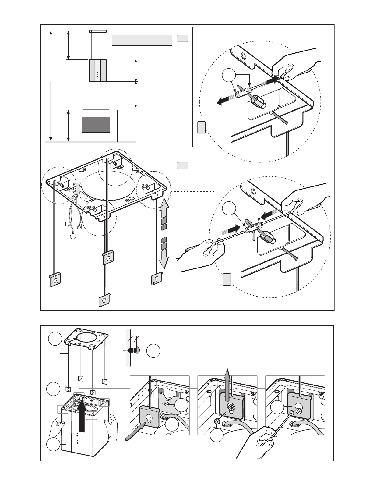
Drill 5 Ø8 holes in the ceiling and tighten 3 screws E without
tightening them completely making sure that the screws are
not inserted in the holes marked with an X on the drill hole
template (the screws and anchors must be suitable for the
type of wall).
- Take structure B (Fig. 2.2) and insert it on the 3 screws that
have not been tightened completely, in correspondence of
the 3 slots.
Make a small rotation to lock it in (Fig. 2.2).
- Tighten the fourth and the fth screw X and the 3 remain-
ing one to lock structure B into its nal position.
To adjust cable height it is necessary to refer to the lengths
shown in (Fig. 3.1)
- To adjust the cable, rst loosen the 2 screws Aof the del
clamp as shown in gure 3.2 (X).
- Once the length of the cable has been adjusted, tighten
the 2 screws Aas shown in gure 3.2 (Y).
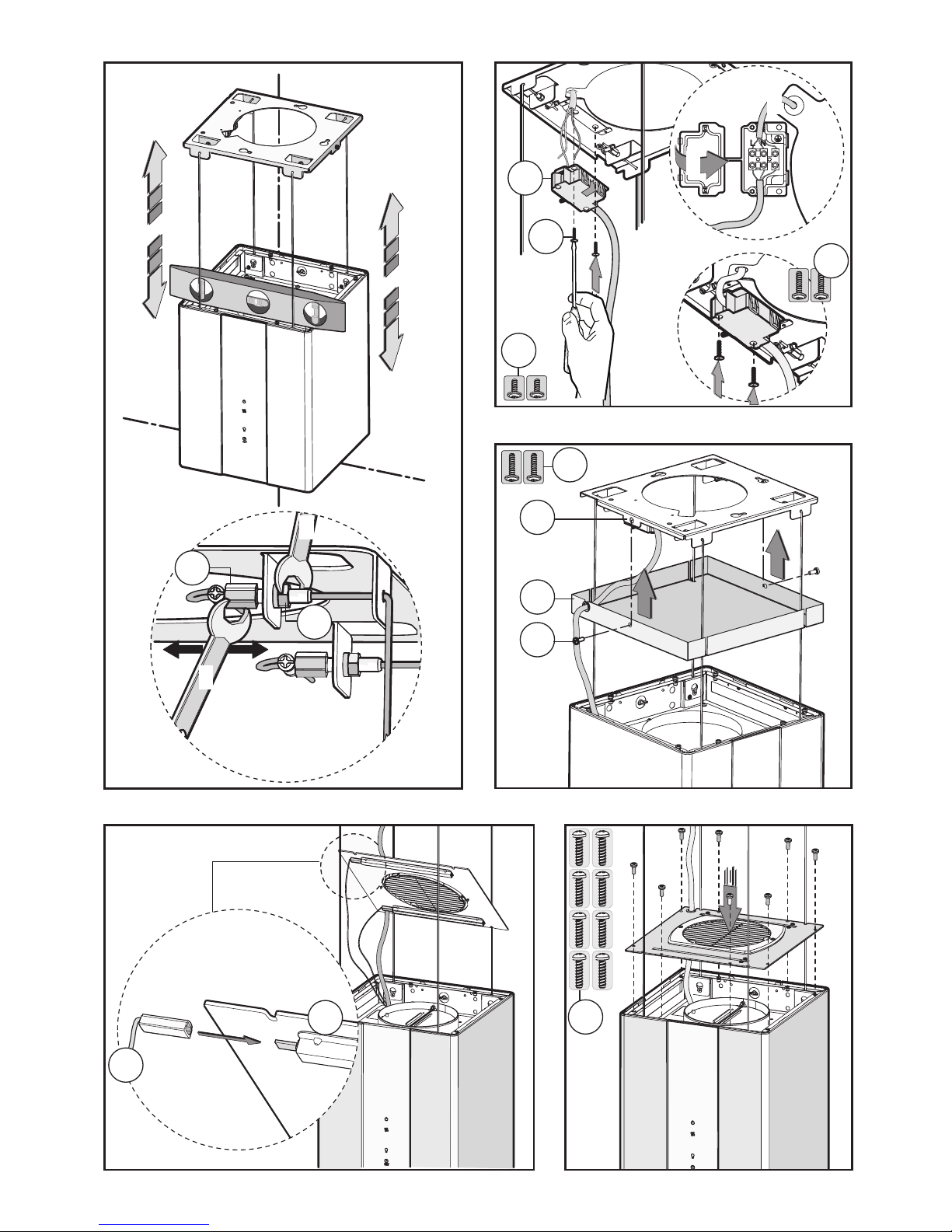
- Couple the hood body Cand the structure Bin correspond-
ence of the 4 slots Fand the four screws G (not completely
tightened) gure 4 - phase 1.
- Rest the hood body on the 4 slots gure 4 - phase 2
- Tighten the 4 screws Gand fasten the structure perma-
nently Bto the hood Cwith the 4 safety screws Hgure 4
- phase 3.
- Using a level align the hood by turning the adjustment
screws Ras shown in gure 5.
- Once the hood is aligned, in order to lock the adjustment
screws permanently R, tighten the nut Das shown in g. 5.
- Before completing the electrical connection, fasten the
box Sto the bracket using the 2 screws Dgure 6 - phase 1.
- Open the box lid Sremoving the adhesive tape.
- Connect to the electrical network as shown in gure 6 -
phase 2.
- Close the lid of the box Sgure 6 - phase 3, and fasten with
the two screws Egure 6 - phase 4
- Take the aesthetic frame Cand using the 2 screws Afasten
it to the structure B g. 7.
Attention! Based on the model that has been purchased,
the product may be equipped with COURTESY LIGHTS OP-
TIONAL, before fastening the small cupola to the hood body
connect the lights as shown in gure 8.
- Pass the power supply cable through the slots of the small
cupola as shown in gure 9.
- Take the small cupola and fasten it to the hood using the 8
screws Gas shown in gure 9.
- If your model is like the one shown in gure 10 it is nec-
essary to fasten the decorative cover M1 - M2.
- In correspondence with the hood body there are 4
(right)+ 4 (left) screws Xthat are not completely tight-
ened gure 10 - phase 1, take the decorative cover M2
and slide it down until it clamps onto the slot phase 2-3-
4-5.
- Take a spanner that is suitable for the screws Xand
tighten them to fasten the decorative cover perma-
nently M2.
- Repeat the same operation for the M1 cover.
• Filtering version
- Before proceeding with the replacement of the regen-
erative lter, open the aesthetic panel.
- Remove the aluminium panel by pulling the handle as
shown in g. 11.
- Remove the brackets from their housing and pull them
outwards. (Fig. 12).
Unlike traditional carbon filters, this carbon filter can be
washed and reactivated for approximately 12-15 times.
With normal hood use, this lter should be cleaned once
every 2-3 months. The lter can be washed in a dishwasher
at the highest temperature using a standard dishwasher
detergent.
After washing, dry the lter in the oven at 100° C for 10-15
minutes to reactivate it.
The lter will retain its odour-absorbing capacity for three
years, after which it will have to be replaced.
USE AND MAINTENANCE
•We recommend that the cooker hood is switched on before
any food is cooked.
We also recommend that the appliance is left running for
15 minutes after the food is cooked, in order to thoroughly
eliminate all contaminated air.
The eective performance of the cooker hood depends on
constant maintenance; the anti-grease lter and the active
carbon lter both require special attention.
• The anti-grease lter is used to trap any grease particles
suspended in the air, therefore is subject to saturation (the
time it takes for the lter to become saturated depends on
the way in which the appliance is used).
-Topreventpotentialrehazards,theanti-greaseltersshould
be washed a minimum of every 2 months (it is possible to use
the dishwasher for this task).
- After a few washes, the colour of the lters may change.This
does not mean they have to be replaced.
If the replacement and washing instructions are not followed,
the anti-grease lters may present a re hazard.
• The active carbon lters are used to purify the air which is
released back into the room.
The active carbon lter saturation level depends on the fre-
quency with which the appliance is used, the type of cooking
performed and the regularity with which the anti-grease
lters are cleaned.
• Clean the cooker hood frequently, both inside and outside,
using a cloth which has been dampened with denatured
alcohol or neutral, non-abrasive liquid detergents.
ATTENTION!
Before proceeding with the replacement of halogen lights it
is necessary to open the aesthetic panel gure 13 - phase 1;
loosen the two screws F lift the small panel Gas shown in g-
ure 13 - phase 2-3.
• Replacing halogen light bulbs (Fig. 13 - phaset 4).
To replace the halogen light bulbs B, remove the glass pane
C using a lever action on the relevant cracks.
Replace the bulbs with new ones of the same type.
Caution: do not touch the light bulb with bare hands.
Optional !
As an optional the product may be equipped with side halo-
gen lamps gure 14.
To replace them, it is necessary to remove the decorative
cover M1 or M2 and repeat the same operations shown in
g. 13 - phase 4“Replacing halogen lamps”.
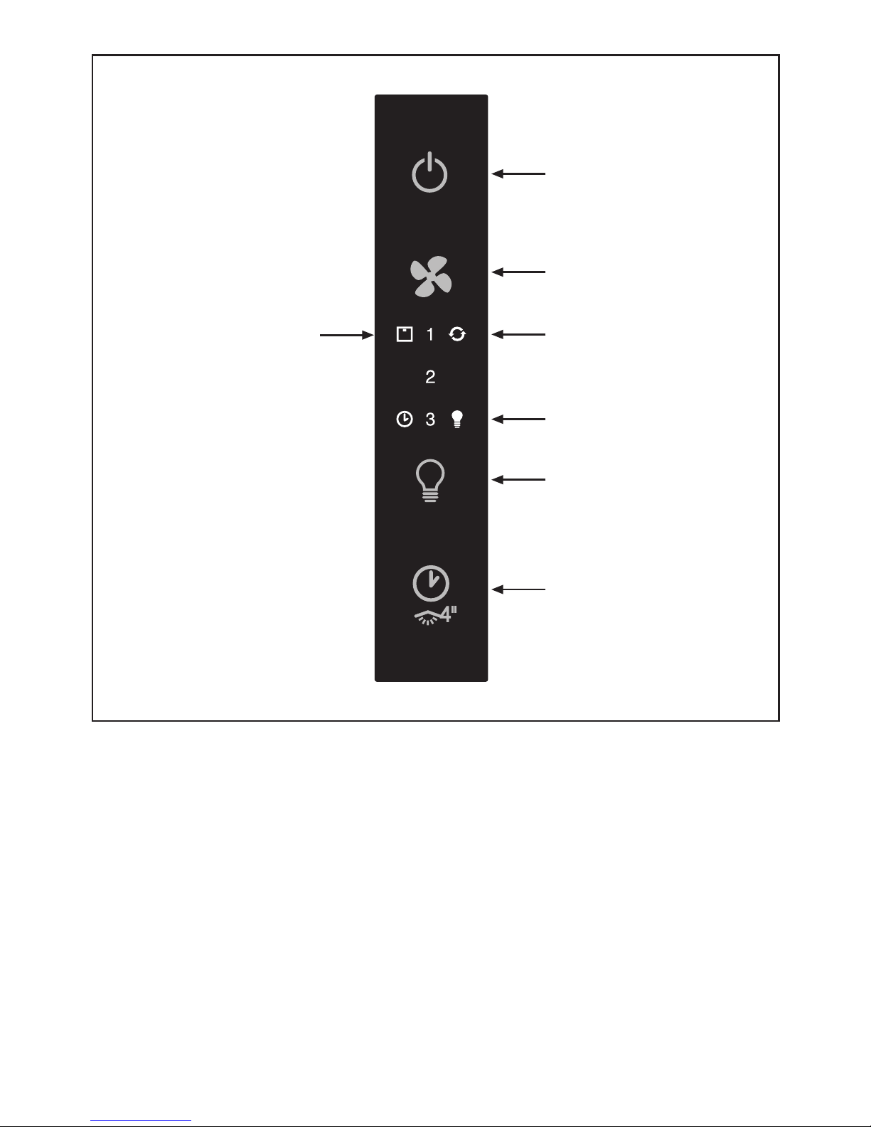
• Commands: (Fig.15)
NOTE: With this control it is possible to manage the appliance
also with a remote control to be requested as accessory.
Power Button (A) = the on / o button switches on and o
the whole hood (motor and lights).
By pressing the button the motor starts at 1st speed.
Fan Speed button (B) = From the OFF position, press once
for the 1st speed, twice for the 2nd speed and three times
- 10 -

for the 3rd speed. In order to activate the intensive speed,
press the button for 5 seconds regardless of the status of the
hood. For each speed only the led indicating the set speed
will turn on. The intensive speed is indicated by the ashing
of the led indicating speed 3. The duration of the intensive
speed is 10 minutes; after this time the hood goes back to
the last set speed.
In order to remove the intensive speed press the power button
and the hood will switch o, or press the Fan speed button
and the speed goes back to the previously set one. Speed of
the hood with cyclic trend.
Light button (C)= There are three light levels: High, medium,
low.
From the o position press once for the high level, twice for
the medium level, three times for the low level and four times
to turn the lights o.
The level of the lights has a cyclic trend: High, medium,
low, o.
ATTENTION! This function is only available with halogen
lamps and NOT with LED lamps.
Timer button (D) = With any type of speed (excluding the
intensive speed), by pressing the button, the timer function
is activated for 15 minutes. After this time has elapsed the
hood will turn o (motor and any light on).
If the product purchased is equipped with optional features
such as the courtesy lights or side spotlights, keep the Timer
button pressed for 4 seconds to turn them on. Complete the
same operation to turn them o.
Lights indicator (E) =The lights indicator will switch on when
the lights are on at any level.
Filters indicator (F) = After 30 minutes of operation, the led
of the lters indicator will switch on, not ashing indicating
that the anti-grease lters have to be washed. To reset the
function (with the hood o), press the Fan speed button for
5 seconds. After this operation, the led of the lters indicator
turns o and the setting of the 30 hours starts again from
the beginning.
After 120 hours the led will ash continuously. This means
that the carbon lters have to be replaced (if present).To reset
the function (with hood o) press the Fan speed button for 5
seconds. After this operation, the led of the indicator turns o
and the setting starts again from the beginning
Clean air indicator (G).
With the hood o, press the Power button (A) for 5 seconds to
activate the clean air function. This will switch on the motor
at speed 1 for 10 minutes every hour. The light indicator will
switch on without ashing and the led of the 1st speed will
switch on. In the remaining 50 minutes the light indicator will
ash. The function can be deactivated by pressing any button
except for the light button.
THE MANUFACTURER DECLINES ALL RESPONSIBILITY
FOR EVENTUAL DAMAGES CAUSED BY BREACHING THE
ABOVE WARNINGS.
- 11 -


- 13 -

- 14 -

- 15 -

3LIK0759
Table of contents
Other Caple Ventilation Hood manuals
Popular Ventilation Hood manuals by other brands

Cosmo
Cosmo IRHP Series Installation Instructions and Use & Care Guide

Electrolux
Electrolux EFP 636 user manual

Miele
Miele DA 3566 Operating and installation instructions

ROBLIN
ROBLIN VELOURS 800 user manual

Whirlpool
Whirlpool 24" (58 CM) Installation and use manual

Sirius Satellite Radio
Sirius Satellite Radio SUF6 installation instructions

Venduro
Venduro RA 90 LP manual

Ortech
Ortech OD-22014 instruction manual

Schweigen
Schweigen Isodrive 1600 installation guide

Elba
Elba ELIO 9365 User instructions

Convotherm
Convotherm CONVOVent min Operating, installation and service manual

ROBINHOOD
ROBINHOOD RHCVI9G - Vetro Island installation instructions