CaptiveAire RTULink User manual

A0026630
July 2021 Rev. 5
RTULink Monitoring and Control
Installation, Operation, and Maintenance Manual
Save these instructions. This document is the property of the owner of this equipment and is required
for future maintenance. Leave this document with the owner when installation or service is complete.
RECEIVING AND INSPECTION
Upon receiving unit, check for any interior and exterior damage, and if found, report it
immediately to the carrier. Also check that all accessory items are accounted for and are
damage free.
WARNING!!
Installation of this control panel should only be performed by a qualified professional who has
read and understands these instructions and is familiar with proper safety precautions.
Improper installation poses serious risk of injury due to electric shock and other potential
hazards. Read this manual thoroughly before installing or servicing this equipment. ALWAYS
disconnect power prior to working on module.

2

3
TABLE OF CONTENTS
WARRANTY...............................................................................................................................................................................................4
SAFETY INFORMATION...........................................................................................................................................................................5
General..............................................................................................................................................................................................5
Installation .........................................................................................................................................................................................5
OVERVIEW................................................................................................................................................................................................6
INSTALLATION OF HARDWARE COMPONENTS ...................................................................................................................................7
RTULink ............................................................................................................................................................................................7
RTULink Control Kit Thermistors.......................................................................................................................................................7
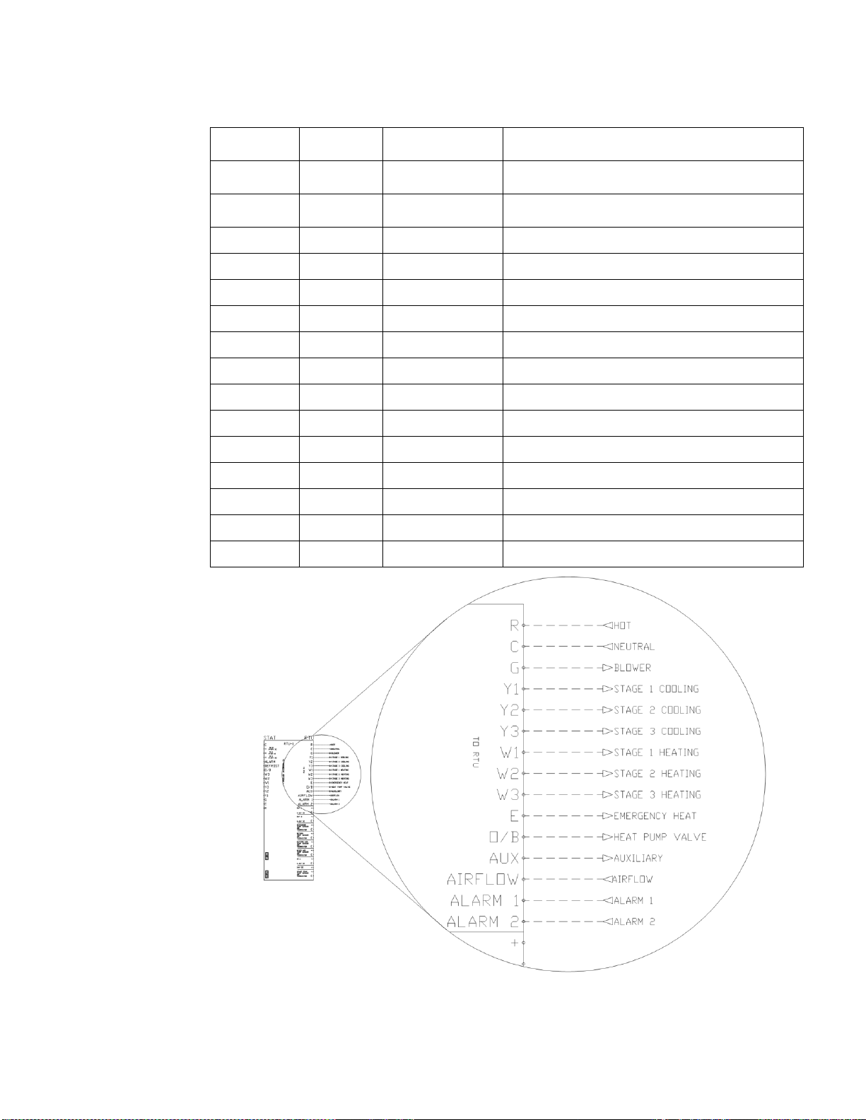
RTULink to RTU Wiring.....................................................................................................................................................................9
Thermostat (optional) ......................................................................................................................................................................10
Space Thermistor –Wall Mount (optional) ......................................................................................................................................11
Modbus Communication Wiring.......................................................................................................................................................13
Optional Sensors..................................................................................................................................................................................14
Temperature and Humidity Sensor –Wall Mount............................................................................................................................14
Relative Humidity –Duct Mount (Return or Discharge)...................................................................................................................17
Carbon Dioxide Sensor –Duct Mount .............................................................................................................................................18
Current Transducer .........................................................................................................................................................................19
Optional Outputs..................................................................................................................................................................................20
Damper/Economizer (0-10VDC)......................................................................................................................................................20
Powered Exhaust Coil Signal ON/OFF (24VAC).............................................................................................................................21
Powered Exhaust (0-10VDC) ..........................................................................................................................................................21
Occupied/Unoccupied Signal (24VAC)............................................................................................................................................22
START-UP PROCEDURE .......................................................................................................................................................................23
RTULink MODES OF OPERATION.........................................................................................................................................................24
Full Control......................................................................................................................................................................................24
Monitor Only....................................................................................................................................................................................24
External Mode .................................................................................................................................................................................24
Emergency Heat..............................................................................................................................................................................24
FUNCTIONALITY.....................................................................................................................................................................................25
Info ..................................................................................................................................................................................................25
Configuration...................................................................................................................................................................................25
Faults...............................................................................................................................................................................................29
Reboot.............................................................................................................................................................................................29
Main Board HMI Menu Tree ............................................................................................................................................................30
Space HMI and Remote Room Sensor Installation..............................................................................................................................35
Space HMI Operation...........................................................................................................................................................................36
Accessing Menu Configurations......................................................................................................................................................36
Remote (HMI) Control Panel ...........................................................................................................................................................36
Space HMI Menu Structure..................................................................................................................................................................36
Space HMI Functionality ......................................................................................................................................................................36
User Settings...................................................................................................................................................................................36
Factory Settings...............................................................................................................................................................................37
Service.................................................................................................................................................................................................40
TROUBLESHOOTING.............................................................................................................................................................................45
Faults...................................................................................................................................................................................................45
COMPONENT DESCRIPTION.................................................................................................................................................................47
Temperature Sensor –Wall Mount..................................................................................................................................................47
Current Sensor................................................................................................................................................................................47
Temperature and Humidity Sensor –Wall Mount............................................................................................................................47
Temperature and Humidity Sensor –Outdoor Mount......................................................................................................................48
Carbon Dioxide Sensor –Duct Mount .............................................................................................................................................48
APPENDIX A............................................................................................................................................................................................49
Daisy Chain Topology:.........................................................................................................................................................................49
Star Topology:......................................................................................................................................................................................49
APPENDIX B............................................................................................................................................................................................50
APPENDIX C ...........................................................................................................................................................................................52
Fixed Dry Bulb Economizer..................................................................................................................................................................52
Differential Dry Bulb Economizer .........................................................................................................................................................53
Fixed Enthalpy Economizer .................................................................................................................................................................54
Differential Enthalpy Economizer.........................................................................................................................................................55
Start-Up and Maintenance Documentation ..............................................................................................................................................56

4
WARRANTY
This equipment is warranted to be free from defects in materials and workmanship, under normal use and service, for a
period of 2-years from date of shipment. This warranty shall not apply if:
1. The equipment is not installed by a qualified installer per the MANUFACTURER’S installation instructions shipped
with the product,
2. The equipment is not installed in accordance with federal, state and local codes and regulations,
3. The equipment is misused or neglected,
4. The equipment is not operated within its published capacity,
5. The invoice is not paid within the terms of the sales agreement.
The MANUFACTURER shall not be liable for incidental and consequential losses and damages potentially attributable to
malfunctioning equipment. Should any part of the equipment prove to be defective in material or workmanship within the
2-year warranty period, upon examination by the MANUFACTURER, such part will be repaired or replaced by
MANUFACTURER at no charge. The BUYER shall pay all labor costs incurred in connection with such repair or
replacement. Equipment shall not be returned without MANUFACTURER’S prior authorization and all returned equipment
shall be shipped by the BUYER, freight prepaid to a destination determined by the MANUFACTURER.

5
SAFETY INFORMATION
General
Monitoring components utilize a mixture of traditional controls along with a “smart” digital circuit board controller, referred
to as the RTULink control board. The RTULink is designed to be installed in the controls cabinet of a roof top unit (RTU).
The RTULink board is powered by 24 VAC, which is provided by the same step-down transformer that is intended to
power the unit’s thermostat.
Some parts of the printed circuit boards can be electrically live and some surfaces can be hot. Inappropriate use and
incorrect installation or operation creates the risk of injury to personnel and/or damage to equipment. All operations
concerning installation, commissioning, and maintenance must be carried out by a qualified, skilled technician who is
familiar with the installation, assembly, commissioning, and operation of the control panel and the application for which it
is being used.
Installation
Ensure proper handling of components and avoid excessive mechanical stress. Do not bend any components during
transport, handling, installation, or maintenance. Do not touch any electronic components or contacts. These boards
contain electrostatically sensitive components, which can easily be damaged by inappropriate handling. Static control
precautions must be adhered to during installation, testing, servicing, and repairing of these boards. Component damage
may result if proper procedures are not followed.
To ensure proper operation, do not install any of the monitoring boards where they will be subjected to adverse
environmental conditions such as combustible, oily, or hazardous vapors; corrosive chemicals; excessive dust, moisture
or vibration; direct sunlight or extreme temperatures.
When working on live panel controllers, applicable national safety regulations must be observed. The electrical installation
must be carried out according to the appropriate regulations (e.g. cable cross-sections, circuit breaker, protective earth
[PE] connection). While this document does make recommendations in regards to these items, national and local codes
must be adhered to.
It is recommended that all thermistor wiring be completed with low voltage thermistor wire and that all low voltage sensor
wiring be completed with 18-5 thermistor wire with braided conductors. All wiring to and from the control boards should be
routed using a code-approved method. Grommets should be used whenever wiring enters or exits an electrical box or
enclosure or whenever it is determined that friction or sharp edges may deteriorate wire. When routing wire internal to
RTUs, utilize existing wire channels within the unit and zip tie the wire to existing wires every two feet within the unit to
prevent it from moving and coming in contact with motors, gears, heating elements, etc.

6
OVERVIEW
The RTULink control board is designed to provide a better
understanding of building HVAC operation. It provides
control variability ranging from monitor only to full control.
Regardless of the level of control that is being utilized, the
board relays all information gathered to the CASLink cloud-
based monitoring and control website. Since CASLink is
cloud-based, it allows all of the features and data offered by
the RTULink to be accessed from any internet-capable
device. Email alerts are generated when scenarios arise
that are detrimental to RTU components or indicate that the
RTU is not operating as designed.
HVAC equipment is currently a set-it-and-forget-it type
product with little to no human interaction after the initial
startup (aside from fixing units when they stop working).
The RTULink breaks this standard by offering remote and
dynamic monitoring, control, and scheduling. Components
whose processes were previously invisible, such as
damper, economizer, powered exhaust, demand control
ventilation, and more, are exposed and controllable
through the RTULink.
If the equipment were to fail under RTULink control, the
personnel in charge of HVAC equipment can remotely
troubleshoot by viewing historical data. Often times a
solution for the failure can be found before repairs are
scheduled, saving time and money.
Figure 1 shows the RTULink board layout. Become
familiar with the pin labeling as this terminology will be
referenced throughout the remainder of this document. In
Figure 1, the left side of the RTULink is the
“THERMOSTAT” side of the board and will be referred as
such throughout the document. In Figure 1, the right side
of the RTULink is the “RTU” side of the board and will be
referred to as such throughout the document.
For more information on CASLink, refer to the latest
version of CASLink “Building Management O&IM”.
Figure 1. RTULink Layout

7
INSTALLATION OF HARDWARE COMPONENTS
It is imperative that these components are installed and operated with the designed specifications and in accordance with
the procedures outlined in this manual. If there are any questions about any items, please call the service department at
1-866-784-6900 for technical support.
RTULink
Open the controls cabinet of the RTU that is being equipped
with an RTULink. Locate a spot in the controls cabinet that
will accommodate the footprint of the RTULink, leaving a
few inches on each side for wiring. Do not alter RTU factory
wiring configuration. Contact support before moving or
rerouting existing RTU wiring. Secure the board with four of
the provided self-tapping screws. Become familiar with the
terminal labeling on the RTULink.
RTULink Control Kit Thermistors
Figure 2 shows a detail of one of the probe thermistors that
is included in the RTULink Control Kit. Each probe
thermistor will be wired to the RTULink. Sensor wiring and
mounting locations internal to the RTU are shown with
dashed lines in Figure 3. A thermistor wiring diagram can
be seen in Figure 4. Sensor descriptions and mounting
instructions can be found in the subsections that follow.
Note: For split system units, mount the return and discharge
sensors directly in the ductwork at a location that will not be
impacted by external factors.
Figure 2. Temperature Sensor Probe
Figure 3. RTULink Kit Installation Detail

8
Outside Air Sensor
The outside air thermistor will measure the temperature of ambient atmospheric air. It should be mounted in the RTU
outside air intake hood. This location is ideal as it is important to keep this sensor out of direct sunlight and weather to
improve the accuracy of readings. If the thermistor cannot be mounted in the intake hood, choose a location on the
outside of the RTU that has the highest percentage of shade throughout the day. Two of the provided self-tapping screws
should be used to secure the sensor to its final location using the mounting flanges.
Label the wires for the outside air thermistor and wire it to the positive (+) and common (C) terminals (thermistor input is
not polarity sensitive) labeled “OUTSIDE AIR TEMP SENSOR 10kΩ” on the TO RTU side of the RTULink control board.
If a penetration is made through an exterior panel of the RTU, ensure it is sealed watertight with caulk, a grommet, or
similar.
Return Air Sensor
The return air thermistor will be
measuring the temperature of
the air in the return duct.
Remove the side panels of the
RTU in order to access the
return duct. The thermistor
should be mounted in a
location internal to the RTU
that is not affected by incoming
outdoor air through the intake
(if applicable). It should also
be mounted in a location that
does not interfere with
operation of the outside air
damper and/or economizer
gears and damper blades.
Two of the provided self-
tapping screws should be used
to secure the sensor to its final
location using the mounting
flanges.
An alternative to mounting the
sensor in the unit is to mount it
in the return duct or return
diffusers in the space, which will provide the most accurate reading. A ½” hole should be drilled in the return duct so that
the sensor probe can be inserted through the duct and into the return airstream. Two of the provided self-tapping screws
should be used to secure the sensor to the duct using the mounting flanges.
Label the wires for the return air thermistor and wire it to the positive (+) and common (C) terminals (thermistor input is not
polarity sensitive) labeled “RETURN AIR TEMP SENSOR 10kΩ” on the RTU side of the RTULink control board.
Discharge Air Sensor
The discharge air sensor will measure the temperature of the air being supplied to the space by the RTU. Remove the
side panels of the RTU in order to access the discharge area (usually directly beneath the blower or burner). It is
important to mount this sensor as far downstream from the heating and/or cooling elements as possible in order to obtain
the most accurate readings. Two of the provided self-tapping screws should be used to secure the sensor to its final
location using the mounting flanges.
An alternative to mounting the sensor in the unit is to mount it in the discharge duct or diffusers in the space, which will
provide the most accurate reading. A 1/2” hole should be drilled in the discharge duct so that the sensor probe can be
inserted through the duct and into the supply airstream. Two of the provided self-tapping screws should be used to
secure the sensor to the duct using the mounting flange. If mounted near the heating components, ensure that at least 9”
of space exists between the probe and the burner elements.
Label the wires for the discharge air thermistor and wire it to the positive (+) and common (C) terminals (thermistor input is
not polarity sensitive) labeled “DISCHARGE AIR TEMP SENSOR 10kΩ” on the RTU side of the RTULink control board.
Figure 4. Control Kit Thermistors –RTULink Wiring

9
RTULink to RTU Wiring
The RTULink will
need to be wired to
the RTU in order to
send control signals.
Table 1 details the
“RTU”side terminals
on the RTULink and
the corresponding
terminal definitions.
Figure 5 shows the
wiring diagram for
the RTULink to RTU
control wiring. Not all
terminals will be
utilized on every unit.
Refer to the specific
RTU and thermostat
documentation to
determine which of
the terminals are
relevant to the
application.
When certain unique
options are present,
it is possible for one
or more of these
terminals to be
repurposed for a
different use. View
the remaining
subsections to
determine which
features will repurpose
board terminals.
Figure 5. RTULink –RTU Wiring
Table 1. RTULink to RTU Wiring Terminals
TERMINAL
LABEL
SIGNAL
VOLTAGE
RTULINK
INPUT/OUTPUT
SIGNAL DESCRIPTION
R
24 VAC
INPUT
24VAC THERMOSTAT TRANSFORMER
HOT
C
COMMON
INPUT
24VAC THERMOSTAT TRANSFORMER
NEUTRAL
G
24 VAC
OUTPUT
BLOWER
Y1
24 VAC
OUTPUT
1ST STAGE COOLING
Y2
24 VAC
OUTPUT
2ND STAGE COOLING
Y3
24 VAC
OUTPUT
3RD STAGE COOLING
W1
24 VAC
OUTPUT
1ST STAGE HEATING
W2
24 VAC
OUTPUT
2ND STAGE HEATING
W3
24 VAC
OUTPUT
3RD STAGE HEATING
E
24 VAC
OUTPUT
EMERGENCY HEAT
O/B
24 VAC
OUTPUT
HEAT PUMP REVERSING VALVE
AUX
24 VAC
OUTPUT
AUXILIARY
AIRFLOW
24 VAC
INPUT
AIRFLOW PROVING
ALARM 1
24 VAC
INPUT
CONFIGURABLE ALARM
ALARM 2
24 VAC
INPUT
CONFIGURABLE ALARM

10
Thermostat (optional)
If a traditional external thermostat will be used to control the RTU, follow these instructions.
The thermostat that is being
used to control the RTU will
need to be wired to the
RTULink. Table 2 details
the “THERMOSTAT” side
terminals on the RTULink
and the corresponding
terminal definitions.
Figure 6 shows the wiring
diagram of the thermostat to
RTULink control wiring.
Figure 7 shows a detail of a
space mounted thermostat
wired to an RTULink. Not
all terminals will be wired,
view RTU and thermostat
documentation to determine
which of the terminals are
relevant to the application.
In a retrofit application, the
thermostat may already be
wired to the RTU. In this
case, there will likely be a
terminal strip in the controls
cabinet of the RTU with the
wiring from the thermostat
landed on one side and the
wiring to the RTU landed on
the other. You will need to
individually disconnect the
incoming thermostat wire and
connect it on the
“THERMOSTAT” side of the
RTULink. Do not
disconnect all of the wires
at once, disconnect wires
one at a time so it is easier to
keep track of the wiring.
When certain additional
features are present
(Occupied/Unoccupied), it is
possible for one or more of
these terminals to be
repurposed for a different
use. The remaining
subsections detail all
additional features and the
corresponding wiring
diagrams.
Figure 6. Thermostat –RTULink Wiring
Table 2. Thermostat to RTULink Wiring Terminals
TERMINAL
LABEL
SIGNAL
VOLTAGE
RTULINK
INPUT/OUTPUT
SIGNAL DESCRIPTION
ALARM
24 VAC
OUTPUT
ALARM NOTIFICATION
DEFROST
24 VAC
OUTPUT
DEFROST NOTIFICATION
O/B
24 VAC
INPUT
HEAT PUMP REVERSING VALVE
W3
24 VAC
INPUT
3RD STAGE HEATING
W2
24 VAC
INPUT
2ND STAGE HEATING
W1
24 VAC
INPUT
1ST STAGE HEATING
Y3
24 VAC
INPUT
3RD STAGE COOLING
Y2
24 VAC
INPUT
2ND STAGE COOLING
Y1
24 VAC
INPUT
1ST STAGE COOLING
G
24 VAC
INPUT
BLOWER
C
COMMON
OUTPUT
24VAC THERMOSTAT
TRANSFORMER NEUTRAL
R
24 VAC
OUTPUT
24VAC THERMOSTAT
TRANSFORMER HOT

11
Space Thermistor –Wall Mount (optional)
If a space temperature sensor/thermistor is called for in the specifications, follow the instructions in this section.
Note: This is not to be confused with the traditional space stat that is used for commercial kitchen ventilation
electrical packages.
A space thermistor will need to be
installed in the zone being supplied
by the RTU. Install a junction box in
an area that will provide accurate
temperature readings. Avoid areas
near windows that are exposed to
sunlight, areas near diffusers, areas
near appliances, areas more than 6
ft. above the floor, etc. Route the
thermistor wire to the RTULink and
connect it to the + and C terminals
(thermistor input is not polarity
sensitive) on the “RTU” side of the
RTULink labeled “SPACE TEMP
10kΩ”. Use the mounting screws
provided with the sensor to secure
the sensor to the junction box.
Figure 8 shows an installation detail
for a stainless steel space thermistor
(PN: A/CP-SP). Figure 9 shows an
installation detail for a space
thermistor with a plastic housing (PN:
A/CP-R2). Figure 10 shows the space sensor terminals and wiring detail.
Figure 7. Thermostat - RTULink Installation Detail
Figure 8. Space Thermistor Detail (Stainless Steel Housing Wall Mount)

12
Figure 10. Space Temperature –RTULink Wiring
Figure 9. Space Thermistor Detail (Plastic Housing Wall Mount)

13
Modbus Communication Wiring
Each RTULink will need to have a path of communication to the communication module (PN: COMM01 located in the
hood panel) via a CAT5 cable. The communication module is typically located in a kitchen ventilation hood control panel,
however it is not limited to that specific location. In most cases, wiring a daisy chain configuration will require the least
amount of wire. See APPENDIX A for typical network layouts in order to determine the best configuration for the
application. Use the J1 and J2 RJ45 ports to connect the RTULinks together using the CAT5 cable. If an RTULink is the
last in a line, it will only have one CAT5 cable connected to it and will require an end of line resistor (PN: EOL120A) in its
unused port (J1 or J2). Figure 11 shows a wiring detail for the Modbus communication network.
All CAT5 cables should be run without RJ45 connectors, and a crimp tool should be used to add connectors once wire
routing is complete. Each RJ45 connector wire should be wired in a T-568-B straight-through configuration. See
APPENDIX B if you are unfamiliar with how to make a straight-through CAT5 cable using RJ45 connectors and a crimp
tool. Once complete, a CAT5 tester should be used to test each length of wire.
Figure 11. Modbus Network –RTULink Wiring

14
Optional Sensors
Temperature and Humidity Sensor –Wall Mount
If a humidity or temperature/humidity sensor is called for in the specifications, follow the instructions in this
section.
A temperature and humidity sensor will need to
be installed in the desired location. It is important
to install the space humidity sensor in a single
gang junction box in an area that will provide
accurate temperature and humidity readings.
Avoid areas near windows that are exposed to
sunlight, areas near diffusers, areas near
appliances, areas more than 6 ft. above the floor,
etc. Any holes in the junction box should be
completely sealed with caulk to prevent humid air
from coming in contact with the sensors circuit
board.
Figure 12 shows an install detail for a wall-
mounted temperature and humidity sensor with a
plastic housing (PN: A/RH3-CP-R2). Figure 13
shows an install detail for a wall-mounted
temperature and humidity sensor with stainless
steel housing (PN: A/RH3-CP-SP). Figure 14
shows a wiring schematic of a space temperature
and humidity sensor that is installed in the space
and connected to the “RTU”Input 1 on the
RTULink. Standard 18-5 thermostat wire should
be used for sensor wiring.
Figure 12. Temperature and Humidity Sensor Detail (Plastic Wall Mount)
Figure 13. Temperature and Humidity Sensor Detail (Stainless Steel Wall Mount Housing)

15
The sensor has a bank of eight dip switches that control the range of the output voltage of the humidity sensor. Switches
seven (7) and eight (8) need to be turned ON, and the rest should remain OFF. These dip switches can be seen in the
sensor detail in Figure 14.
Once the sensor is wired to an input, enter the configuration menu of the RTULink via the onboard HMI and configure the
corresponding input for the humidity sensor that was installed. In the Figure 14 example, “RTU IN 1” would be configured
for “SPACE RH”.
Figure 14. Space Mounted Temp/Humidity Sensor Wiring

16
Temperature and Humidity Sensor –Outdoor Mount
If exterior mounted temperature and humidity sensors are called for in the specifications, follow the instructions
in this section.
An outdoor temperature and humidity sensor
(PN: A/RH3-CP-O10) shall be mounted in an
outdoor location that is free from direct
weather and sunlight. This can be under an
eave, intake, or any other area that is out of
the elements.
Figure 15 shows a detail and terminology of
the sensor. The sensor probe must be facing
downward. Mount the sensor in the desired
location using screws inserted into the
mounting flanges. Use EMT conduit where
sensor wiring would be exposed to the
elements when routing wire back to the
RTULink control board. When holes are
made for connecting conduit to the knockout,
make sure that they are properly sealed with
liquid tight fittings to prevent moisture from
entering the sensor housing. Standard 18-5
thermostat wire should be used for sensor
wiring.
The sensor has a bank of eight dip switches
that control the range of the output voltage of
the humidity sensor. Switches seven (7) and
eight (8) need to be turned ON and the rest
should remain OFF. These dip switches can be seen in the sensor detail in Figure 16.
Figure 16 is a wiring diagram of
an outside air temperature and
humidity sensor connecting to
the “RTU”Input 1 on the
RTULink.
Once the sensor is wired to an
input, enter the configuration
menu via the onboard HMI and
configure the corresponding
input for the Outdoor Air humidity
sensor that was installed. In the
above example, “RTU IN 1”
would be configured for “OA
RH”.
Figure 16. RTULink - Outside Air Temp and RH
Figure 15. Outdoor Temperature/Humidity Sensor

17
Relative Humidity –Duct Mount (Return or Discharge)
If a duct mounted humidity sensors is called for in the specifications, follow the instructions in this section.
A duct mounted (return or discharge
duct) humidity sensor (PN: A/RH3-
DO10) shall be installed in the duct of
the RTU.
Figure 17 shows a detail and
terminology of the sensor. A 1” hole
should be drilled in the duct so the
sensor probe can be inserted into the
airstream. The sensor should be
secured to the duct using the
mounting flanges. Ensure that any
holes in the duct are properly sealed.
Use EMT conduit where sensor wiring
would be exposed to the elements
when routing wire back to the
RTULink control board. Standard 18-
5 thermostat wire should be used for
sensor wiring.
The sensor has a bank of eight dip
switches that control the range of the
output voltage of the humidity sensor.
Switches seven (7) and eight (8) need
to be turned ON and the rest should
remain OFF. These dip switches can
be seen in the sensor detail in Figure
18.
Figure 18 is a wiring diagram of a duct
mounted humidity sensor that is wired
to the “RTU” Input 1 on the RTULink.
Once the sensor is wired to an input,
enter the configuration menu via the
onboard HMI and configure the
corresponding input for the humidity
sensor that was installed. In the
example in Figure 18, the sensor was
installed in the return duct, so “RTU IN
1” would be configured for “RA RH”.
Figure 17. Duct Mount Humidity Sensor
Figure 18. RTULink - Duct Mount RH

18
Carbon Dioxide Sensor –Duct Mount
If a CO2sensor is called for in the specifications or if CO2based demand control ventilation will be used for
RTULink control, follow the instructions in this section.
A CO2sensor (PN:
A/CO2-D010) will need to
be installed in a duct to
measure carbon dioxide
content of the air. A
sensor detail and
terminology can be seen
in Figure 19. The most
common application is to
install this sensor in the
return air duct, which
effectively measures the
CO2of the space. A 1½”
or 1¼” hole should be
drilled in the duct so that
the sensor can be
inserted into the
airstream. Make sure
that the provided gasket
is installed on the sensor
to prevent duct leakage.
Refer to the airflow arrow on the sensor to determine the proper mounting orientation (air should hit the side of the probe
opposite of the airways). Once the sensor is in its final position, secure it to the duct with self-tapping screws. Wire nuts
will be provided with the sensor so that wire connections can be made. The sensor will be powered by 24VDC which will
be supplied by the RTULink. The output voltage of the CO2sensor will need to be wired to a 0-10VDC input on the
RTULink. A wiring diagram of a CO2sensor wired to Input 1 on the “RTU” side of the RTULink can be seen in Figure 20.
Standard 18-5 wire should be
used for sensor wiring.
Once the sensor is wired to an
RTULink input, be sure to enter
the configuration menu via the
onboard HMI and configure this
input for “CO2”. In the Figure 20
example, “RTU IN 1” will need to
be configured as “CO2”.
Note: This sensor has a rolling
calibration that utilizes a
normal occupancy CO2curve
as a reference. If the building
or space that this sensor will be
installed in does not follow a
normal occupancy bell curve,
contact support.
Figure 20. CO2 –RTULink Wiring
Figure 19. CO2 Sensor Detail (Duct Mount)

19
Current Transducer
If current transducer(s) are called for in the specifications, follow the instructions in this section.
A current transducer (CT) will be
installed in the RTU control
panel with mounting screws or
on a piece of din rail. Energy
consumption will be measured
by routing the line wiring
through the hole in the CT. For
an RTU application, the CTs
can measure condenser power
consumption, heating element
power consumption (if electric),
or total RTU power
consumption. These lines can
usually be accessed inside of
the RTU. Refer to RTU
manufacturer documentation for
detailed wiring schematics.
Only one wire can be inserted
through each CT for measurement.
Set the current transducer jumper to monitor the closest amperage that is equal to or higher than the maximum expected
current of the circuit that will be monitored (do not account for inrush current). For example, a condenser with a maximum
amperage rating of 80 amps will have a current transducer jumper installed to monitor 100 amps (100 amp is the lowest
setting that exceeds 80 amp). Connect the positive (+) and negative (-) terminals of the current transducer to the positive
(+) and negative (-) terminals of a 0-10VDC input on the RTULink. PN: A/CTV-50 is used to measure components in the
range of 10, 20, and 50 amps. PN: A/CTV-250 is used to monitor components in the range of 100, 200, and 250 amps.
Figure 21 shows a detail and terminology of a current transducer. For specialized applications out of these ranges
contact support.
Figure 22 shows a wiring diagram of a current
transducer that is wired to Input 1 on the “RTU” side of
the board and whose jumper set to measure 10 Amps.
Standard 18-2 wire should be used for sensor wiring.
Once the sensor is wired to an input, enter the
configuration menu via the onboard HMI and configure
the corresponding input for “Current X”. The X will
represent the number of the current transducer that is
installed on the RTULink (if this is the second, the X will
be a 2). Next, “Current X” will need to be configured
with the corresponding Amps/V. In the above example,
the “RTU IN 1” would be configured for “Current 1”
(since this is the first and only current transducer wired
to the RTULink) and “Current 1” would then be
configured for 1 Amps/V.
Figure 22. CT –RTULink Wiring
Figure 21. Current Transducer Detail

20
Optional Outputs
Damper/Economizer (0-10VDC)
If the RTULink will be controlling
an 0-10VDC damper or
economizer, it must be
configured to accommodate this
feature. Choose a 0-10VDC
output on the “RTU”side of the
RTULink that will be controlling
the economizer. Figure 23 is a
wiring schematic of an
economizer connected to Output
#1. View the FUNCTIONALITY
section of this manual to
determine how to setup an
economizer and how to change
the set points that are associated
with it. There are four
economizer types that the
RTULink has the capability of
controlling: fixed dry bulb,
differential dry bulb, fixed
enthalpy, or differential enthalpy.
Each economizer requires
specific auxiliary sensors which
are explained in Table 3.
For enthalpy economizers,
enthalpy is calculated using
temperature and relative
humidity.
In Table 3, the outside air enthalpy is represented as OAE and the return air enthalpy is represented as RAE. View
APPENDIX C for psychometric chart visuals on how the four economizer types operate.
Figure 23. Economizer Connected to Output #1 (0-10VDC)
Table 3. Economizer Sensors
Economizer
Type
Required Sensor(s)
Modulate Open If
Fixed Dry Bulb
•Outside Air Temperature (OAT)*
If OAT < (Dry Bulb Set Point)
Differential Dry
Bulb
•Outside Air Temperature (OAT)*
•Return Air Temperature (RAT)*
If OAT < RAT
Fixed Enthalpy
•Outside Air Temperature (OAT)*
•Outside Air Relative Humidity (OARH)
If OAE < (Enthalpy Set Point)
Differential
Enthalpy
•Outside Air Temperature (OAT)*
•Outside Air Relative Humidity (OARH)
•Return Air Temperature (RAT)*
•Return Air Relative Humidity (RARH)
If OAE < (RAE)
*Already included by default
Table of contents
Other CaptiveAire Industrial Equipment manuals
Popular Industrial Equipment manuals by other brands

HOLZMANN MASCHINEN
HOLZMANN MASCHINEN FS160SOLID operating manual

Beckhoff
Beckhoff AA3100 operating instructions

Asco
Asco 5350 user guide

Watts
Watts 994-FS Series INSTRUCTION, INSTALLATION, MAINTENANCE AND REPAIR MANUAL

CAB
CAB PRESTIGE PS1.60FA User handbook

Eaton
Eaton COOPER POWER SERIES Assembly and installation instructions