21.VW.2210.3063_BA_V00_EN
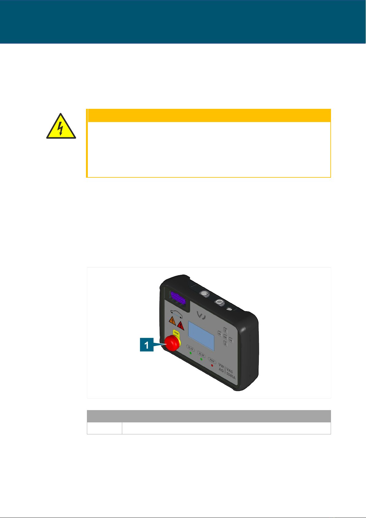
Pressing the emergency stop button
Push in the emergency stop button until it clicks into place.
All electrical connections are immediately interrupted.
Resetting the emergency stop button
1. Switch off the diagnostic box at the main switch (see chapter “Switching off the
diagnostic box”).
2. Turn the emergency stop button clockwise and pull out until it clicks into place.
Power supply to the diagnostic box is restored. You can now switch the diagnostic box
on again (see chapter “Switching on the diagnostic box”).
If you press the emergency stop button, the current diagnostics will be interrupted and
cannot be resumed. Error messages may appear in the diagnostic program.
Intended use
The diagnostic box is a tool for performing diagnostics on components outside the vehicle
network (stand-alone components).
The diagnostic box supplies the power to the component and has an OBD port for
establishing communication. This enables you to use diagnostic systems (e.g. ODIS Service in
combination with VC interface VAS 6154) that usually access components via the OBD
connector in the vehicle.
Depending on your requirements, the diagnostic system and the VC interface can
communicate with the stand-alone component in three different operating modes:
•Soft bridge mode (SB)
•Gateway mode (GW)
•Hard bridge mode (HB)
Connect the diagnostic box to the vehicle component you want to test using adapter cables.
The diagnostic box can be updated, allowing it to be adapted to future applications with a
firmware update. The diagnostic box is downward compatible with its predecessor the VAS
5581 and the corresponding adapter cables.
Use only the power supply belonging to the diagnostic box with the power supply cable
suitable for the country of use, and use only the rechargeable batteries belonging to the
diagnostic box (see chapters “Scope of delivery” and “Configuration”). Observe the operating
manual from the manufacturer of the power supply! Use only the plug connections on the
vehicle that the manufacturer has specified in the guided fault finding.
In this operating manual, vehicle manufacturers are exclusively defined as vehicle
manufacturers in the Volkswagen Group.
Any use beyond what is listed here is prohibited.