St. Jude Medical QUANTIEN User manual

QUANTIEN™ Measurement System
Diagnostic Computer
C12787
Instructions for Use
State: Released Date: 2019.03.06 22:30 GMT

CAUTION: Federal (USA) law restricts this device to sale by or on the order of a physician.
Unless otherwise noted, ™ indicates that the name is a trademark of, or licensed
to, St. Jude Medical or one of
its subsidiaries. ST.
JUDE MEDICAL and the nine-squares symbol are trademarks and service marks of St.
Jude
Medical, LLC and its related companies.
Pat.
http://patents.sjm.com
©
2019 St. Jude Medical, LLC. All Rights Reserved.
State: Released Date: 2019.03.06 22:30 GMT

i
Contents
QUANTIEN™ Measurement System .......................................................................... 1
Introduction to the Instructions for Use (IFU) ............................................................. 1
Highlights Used.................................................................................................................1
Product Description................................................................................................... 2
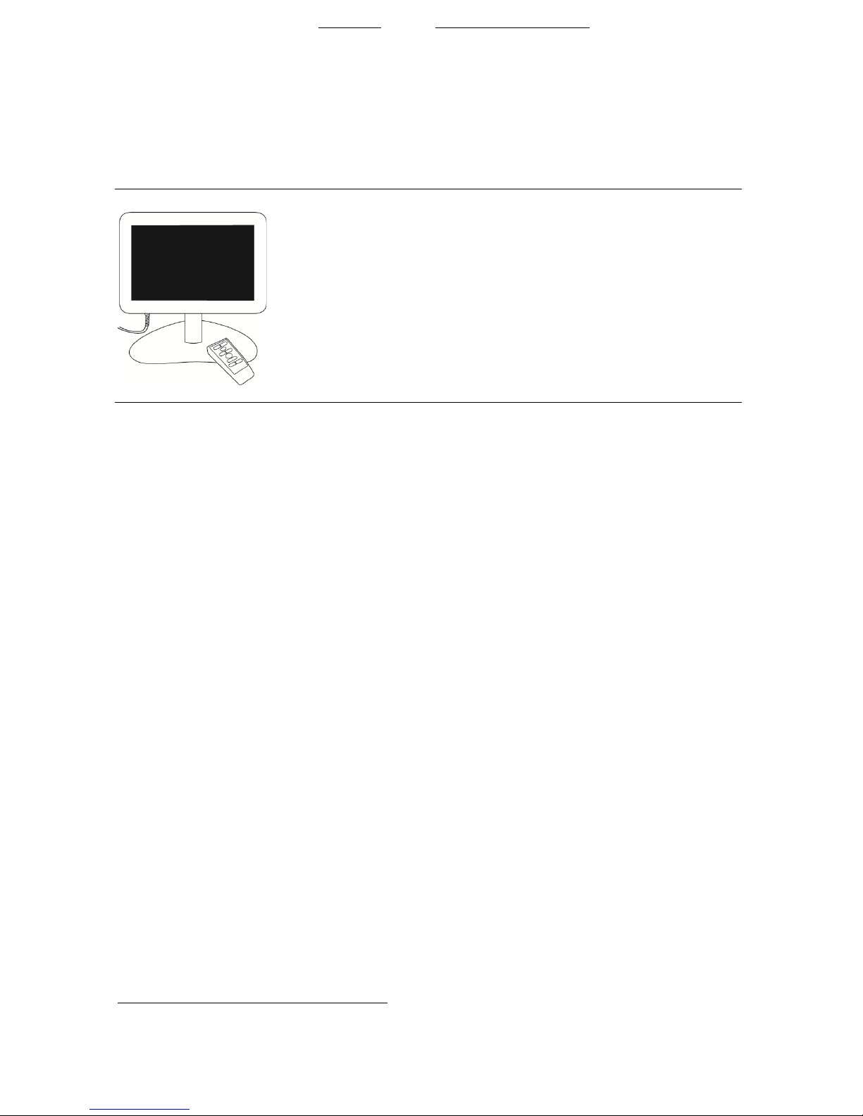
Introduction ......................................................................................................................2
Intended Use ....................................................................................................................3
Indications for Use ............................................................................................................3
Contraindications...............................................................................................................3
Users................................................................................................................................3
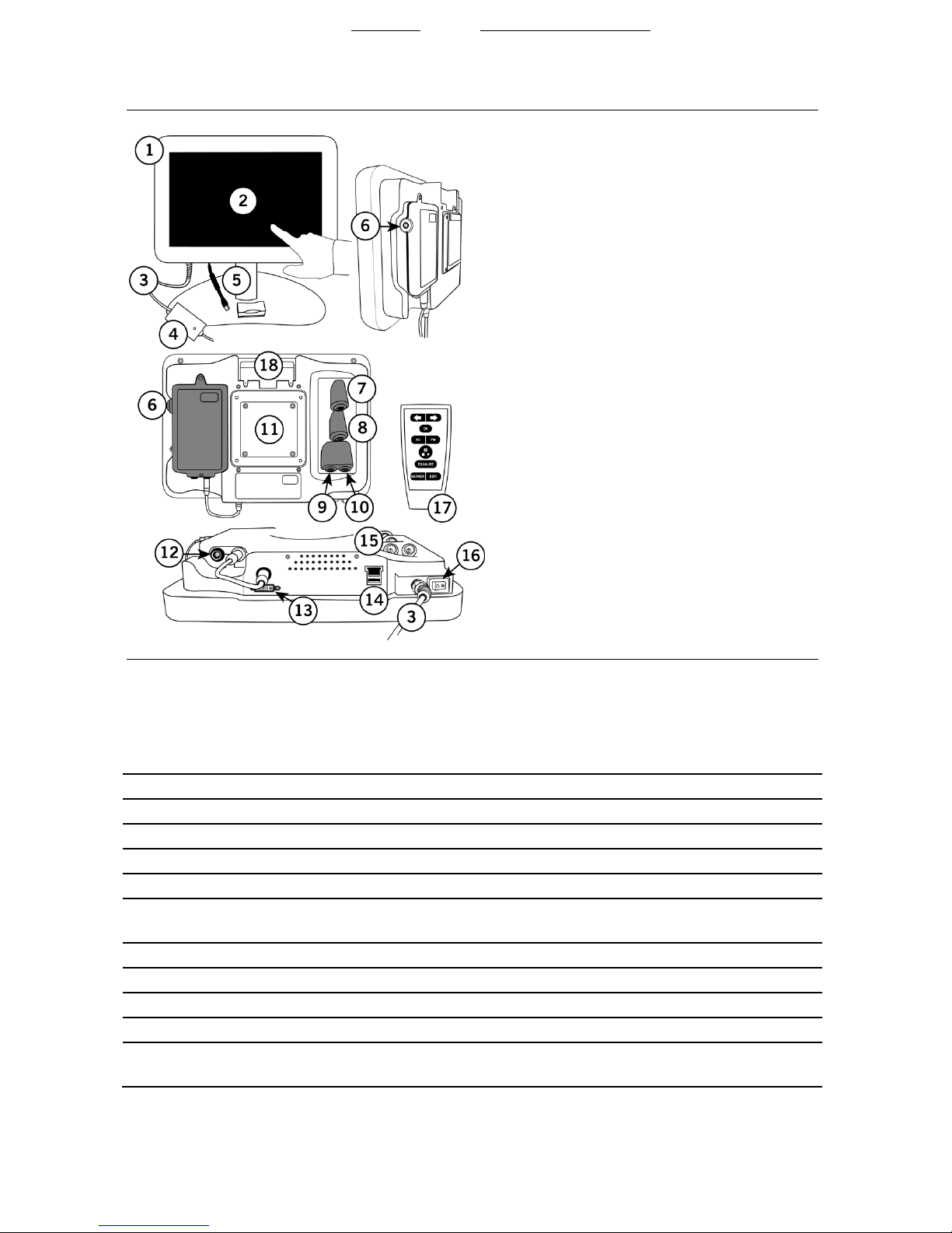
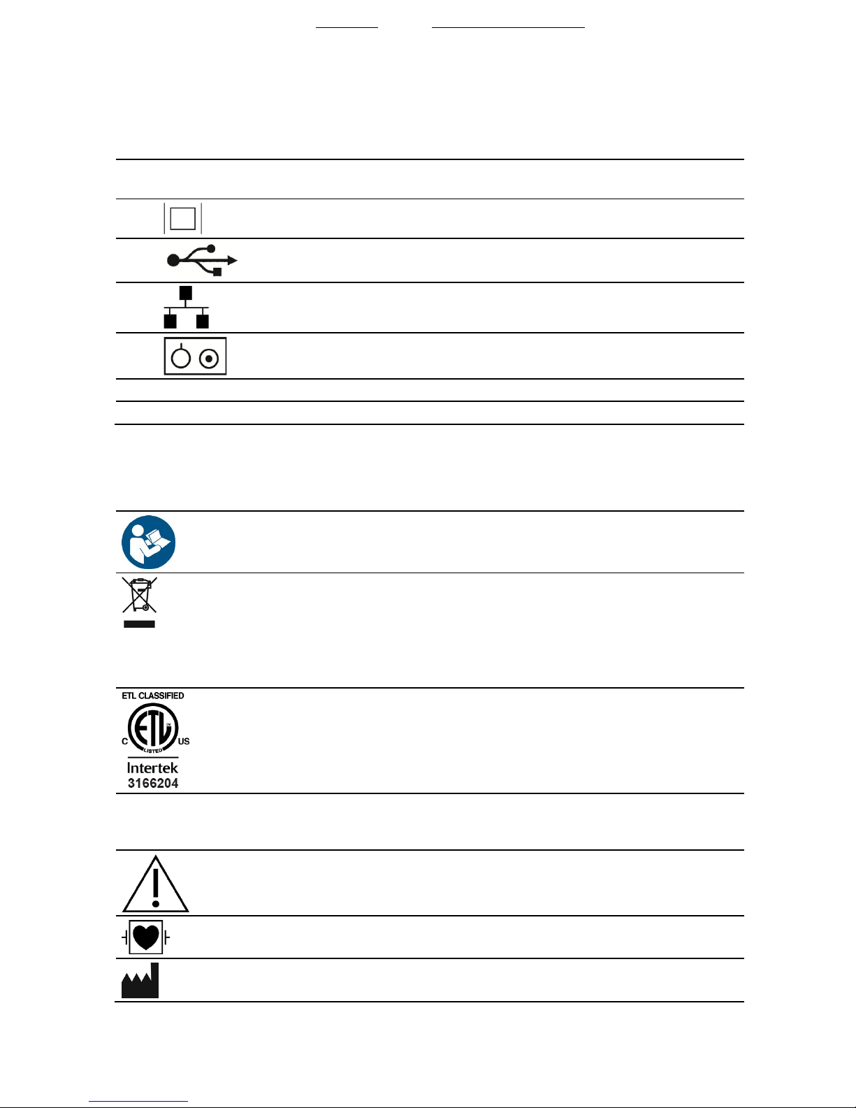
Product Interface and Symbols ..........................................................................................3
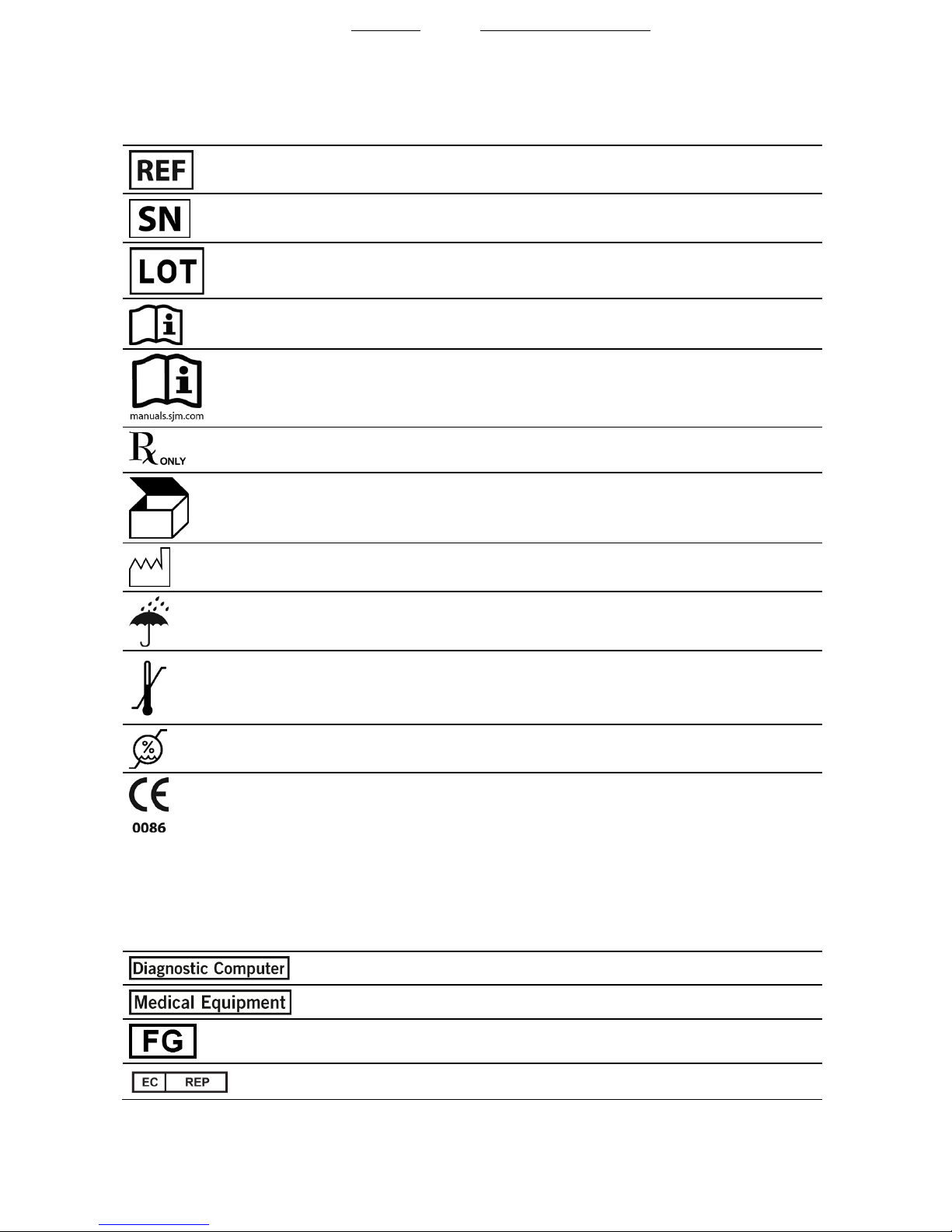
Symbols Used on Product, Packaging, and IFU ..................................................................5
Remote Control Symbols and Functions..............................................................................7
Additional Devices and Accessories....................................................................................7
General Warnings, Precautions, and Safety Information.......................................................8
Graphical User Interface ..................................................................................................10
Indicator Lights and Sounds.............................................................................................12
Basic Setup Using Wi-Box™ AO Transmitter (Wireless AO Source)........................... 12
Install Wi-Box™ AO Transmitter .......................................................................................13
Unpack QUANTIEN™ Measurement System ....................................................................13
Mount QUANTIEN™ Main Unit in the Cath Lab ................................................................14
Room Configuration.........................................................................................................16
Measure FFR or RFR .............................................................................................. 17
Warnings and Precautions ...............................................................................................17
Live Window....................................................................................................................18
FFR/RFR Measurement Procedure...................................................................................19
Review Recordings.................................................................................................. 25
Review Window ...............................................................................................................25
Study Summary...............................................................................................................26
Review Recording............................................................................................................26
Export Data .....................................................................................................................28
Review Archived Studies ......................................................................................... 30
Archive Window...............................................................................................................30
Export and Delete Files in Archive ....................................................................................31
Settings................................................................................................................... 32
System Settings Overview.................................................................................................32
Room Setup ....................................................................................................................32
Regional Settings.............................................................................................................35
User Settings...................................................................................................................35
Security Settings..............................................................................................................36
Connections ....................................................................................................................37
Network Configuration .....................................................................................................41
Display Settings...............................................................................................................44
Service............................................................................................................................46
Demo Mode ....................................................................................................................46
Troubleshooting ...................................................................................................... 47
On Screen Messages .......................................................................................................47
State: Released Date: 2019.03.06 22:30 GMT

ii
Tracing EM Interference...................................................................................................53
Troubleshooting Tables ....................................................................................................55
Maintenance...........................................................................................................67
Remote Control Battery ....................................................................................................67
System Backup Battery....................................................................................................68
Disposal ..........................................................................................................................68
Cleaning..........................................................................................................................68
Preventative Maintenance Schedule .................................................................................68
Leakage Current Measurement.........................................................................................69
Testing PW IN .................................................................................................................70
Testing PW OUT and Associated Monitor Channel.............................................................71
Testing AUX IN 1 and Associated Monitor Channel............................................................72
Testing AUX IN 2 and Associated Monitor Channel............................................................73
Testing AUX OUT 1 & 2 and Associated Monitor Channel ..................................................73
Test Probes .....................................................................................................................74
Leakage Adapters ............................................................................................................75
Service or Repair .............................................................................................................75
Technical Specifications ..........................................................................................75
Pressure Measurement ....................................................................................................75
Electrical Specifications....................................................................................................75
Specifications Interfaces...................................................................................................75
Dimensions .....................................................................................................................77
Environmental Conditions.................................................................................................77
Isolation Diagram.............................................................................................................78
File Formats ....................................................................................................................79
Compliance with Regulatory Requirements ..............................................................79
Compliance with Standards and Directives........................................................................79
Guidance and Manufacturer’s Declaration - Electromagnetic Emissions..............................80
Guidance and Manufacturer’s Declaration - Electromagnetic Immunity...............................81
Recommended Separation Distances Between Portable and Mobile RF Communications
Equipment and QUANTIEN™ System ...........................................................................83
Warranty Disclaimer ................................................................................................84
Australian Warranty .................................................................................................84
State: Released Date: 2019.03.06 22:30 GMT

1
QUANTIEN™ Measurement System
Introduction to the Instructions for Use (IFU)
This IFU contains both the instructions for use for the operator and technical information
including installation and maintenance instructions.
This IFU describes the handling of the QUANTIEN™ measurement system. For operation of the
QUANTIEN measurement system, other devices need to be connected. Consult the IFU for each
of these devices for details on handling and safety information.
NOTE: Pictures are shown for example only.
Highlights Used
Bold font is used in the IFU to identify the names of buttons, menus, and windows, and is also
used for some subheadings.
Warnings, cautions and notes are used in the following way:
WARNING: The personal safety of the patient or user may be involved.
Disregarding this information could result in injury.
CAUTION: These instructions point out special service procedures or precautions
that you must follow to avoid damaging the device.
Note: This provides information you might find especially useful or information that
facilitates maintenance or clarifies important instructions.
The following abbreviations and terms are used in this IFU:
Table 1. Abbreviations used in this IFU
Abbreviatio
n
Description
AO
Aortic Pressure
Cath lab
Catheterization laboratory
CF Cardiac Floating
PCI
Percutaneous Coronary Intervention
FFR
Fractional Flow Reserve (Pd/Pa, measured at maximum hyperemia)
HRS
Hemodynamic recording system (Hemodynamic recording system)
IFU Instruction for Use
Pa
Proximal Pressure
Pd
Distal Pressure
PW
PressureWire™ guidewire
RFR Resting Full-cycle Ratio
Study As used in this IFU a study consists of all FFR measurement recordings for one
patient on the same occasion/procedure
State: Released Date: 2019.03.06 22:30 GMT

2
Product Description
Introduction
Figure 1. QUANTIEN™ Main Unit with Table Stand and Remote Control
The QUANTIEN™ measurement system is a diagnostic computer designed to record, compute,
display and store data from PressureWire™ guidewire and other external transducers. The
information is displayed as graphs as well as numerical values on the screen. Data includes, but is
not limited to: systolic, diastolic and mean blood pressure, heart rate, Fractional Flow Reserve
(FFR), and data from ECG.
Fractional Flow Reserve (FFR) is the ratio of distal coronary arterial pressure (Pd) to aortic
pressure (Pa), measured during hyperemia. It provides the maximal blood flow in the presence of
a stenosis as a fraction of the achievable blood flow that would exist in the hypothetical situation
that the stenosis was not present. Pd/Pa at rest is the ratio of distal coronary arterial pressure to
aortic pressure measured at resting conditions. Resting Full-cycle Ratio (RFR) is the ratio of Pd to
Pa at a point in the cardiac cycle where the Pd/Pa ratio is minimal. RFR is designed to be used at
rest and, in contrast to Pd/Pa at rest, is a sub-cycle metric.
These physiological parameters are measured when the QUANTIEN™ measurement system is
used with the manufacturer’s distal intracoronary pressure transducer and a proximal aortic
pressure transducer.
The physician may use the FFR, Pd/Pa at rest and RFR parameters, along with knowledge of
patient history, medical expertise and clinical judgment to determine if therapeutic intervention is
indicated.
Information on screen can also be transferred to an external HRS or to an external video monitor.
Recorded procedures can be viewed on a PC for post-procedural review and analysis with
application specific viewing software installed, such as RadiView™ software.
Additional functions let you import a patient work list from the hospital DICOM1‡ system, export
recorded measurement data to DICOM or to an external server location or save it to a USB
memory stick.
1DICOM is a registered trademark of the National Electrical Manufacturers Association for its standards publications relating to
digital communications of medical information.
State: Released Date: 2019.03.06 22:30 GMT

3
Intended Use
The QUANTIEN™ measurement system is intended for use in catheterization and related
cardiovascular specialty laboratories to compute and display various physiological parameters
based on the output from one or more electrodes, transducers or measuring devices.
Indications for Use
The QUANTIEN™ measurement system is indicated to provide hemodynamic information for use
in the diagnosis and treatment of coronary or peripheral artery disease.
The QUANTIEN measurement system is intended for use in the catheterization and related
cardiovascular specialty laboratories to compute, and display various physiological parameters
based on the output from one or more electrodes, transducers, or measuring devices.
Contraindications
The device has no patient alarm functions. Do not use it for cardiac monitoring.
Users
Normal operation: The QUANTIEN™ measurement system should be handled by or supervised
by a physician with training in catheterization laboratory procedures.
Preventative maintenance: Hospital technician
Installation: Hospital technician/IT personnel, St. Jude Medical sales representative/technician.
Product Interface and Symbols
The QUANTIEN™ measurement system includes a main unit with a touch screen user interface
and several input/output ports, a remote control, a power cable and an ethernet patch cable with
isolator.
State: Released Date: 2019.03.06 22:30 GMT

4
Figure 2. QUANTIEN™ Interface
Table 2. QUANTIEN™ Interface and Port Symbols
No.
Symbol or marking
Explanation
1 N/A QUANTIEN™ main unit
2 N/A Display – touch screen
3 N/A Power cable with power supply unit
4 N/A Indicator light, power supply
5 N/A Patch cable and isolation box
6 PressureWire™ IN PressureWire IN on PressureWire interface – Pd signal from
PressureWire guidewire (white sleeve). Connection to applied part.
7 AUX IN 1 AO signal from cath lab recording system (yellow sleeve)
8 AUX IN 2 ECG signal from HRS (black sleeve)
9 AUX OUT 1 Pa, Pd or reference signal output (grey sleeve)
10 AUX OUT 2 Pa, Pd or reference signal output (grey sleeve)
11 N/A Heat sink and connection block for mounting bracket (VESA
standard 75 x 75 mm and 100 x 100 mm)
State: Released Date: 2019.03.06 22:30 GMT

5
Table 2. QUANTIEN™ Interface and Port Symbols
No.
Symbol or marking
Explanation
12 PressureWire™ OUT PressureWire OUT on PressureWire interface – Pd signal to external
monitor (green sleeve). Connection to applied part.
13
DVI-I output – video display/monitor
14
USB port – Memory stick, data export, software upgrade
15
Ethernet – network connection
16
On/Off switch
17 N/A Remote control
18 N/A Slot for storing remote control
Symbols Used on Product, Packaging, and IFU
The following symbols may be found on the product or product label:
Symbol
Description
Follow instructions for use. (Symbol appears blue on product labeling.)
Affixed to this device in accordance with European Council Directives
2002/96/EC and 2006/66/EC.
These directives call for separate collection and disposal of electrical and
electronic equipment. Sorting such waste and removing it from other
forms of waste lessens the contribution of potentially toxic substances
into municipal disposal systems and into the larger ecosystem.
Intertek Safety Agency Certification Mark
Canada 310
This device complies with RSS-310 of Industry Canada. Operation is
subject to the condition that this device does not cause harmful
interference.
Caution
Defibrillation-proof Type CF equipment
Manufacturer
State: Released Date: 2019.03.06 22:30 GMT

6
The following symbols may be found on the product or product label:
Symbol
Description
Catalog number
Serial number
Lot Number
Consult instructions for use
Follow instructions for use on this website
CAUTION: Federal (USA) law restricts this device to sale by or on the
order of a physician.
Quantity
Date of Manufacture
Keep dry
Temperature limitations
Humidity limitation
European conformity, affixed according to the relevant provisions of MD
directives 93/42/EEC and 2011/65/EU, and RE directive 2014/53/EU
Annex II. Hereby, St. Jude Medical declares that this device complies
with the essential requirements and other relevant provisions of these
directives.
The full text of the European Union RE directive 2014/53/EU declaration
of conformity is available at the following internet address:
www.sjmglobal.com/euconformity.
Diagnostic Computer
Medical equipment
Finished good
Authorized Representative in the European Community
State: Released Date: 2019.03.06 22:30 GMT

7
The following symbols may be found on the product or product label:
Symbol
Description
Do not use if package is damaged
Software version
Software upgrade kit
Instructions for use
Australian Sponsor
Remote Control Symbols and Functions
The remote control can be used instead of the touch screen to perform FFR/RFR measurements,
and for navigation/selections in other windows (limited function). The remote control signal is
indicated by a white indicator flash at the top, right corner of the open window.
Figure 3. Remote Control
1.
Arrows
: Move right/left (up/down), select a specific
menu button/value or move the cursor in the
Review
window. A selected menu button or value is always
highlighted.
2.
OK
/Enter: Confirm the selection of a menu button or
function, or confirm entered values.
3.
AO
: Open the Pa drop-down menu in
Live
window,
allow zero of the AO pressure.
4.
PW
: Open the Pd drop-down menu in
Live
window,
allow zero of the PressureWire™ guidewire.
5.
Live
: Main function key, start/stop/recording, go directly
to
Live
window.
6.
EQUALIZE
: Equalize AO and Pd pressures.
7.
MARKER
: Add marker during recording.
8.
EDIT
: Open Annotation dialogue box in the
Review
window.
Additional Devices and Accessories
Devices and accessories that are required or optional for use with the QUANTIEN™ measurement
system are listed in the tables below. Only these products are permitted to be used with the
QUANTIEN measurement system. All are ordered separately, either from St. Jude Medical or from
other manufacturers.
State: Released Date: 2019.03.06 22:30 GMT

8
Table 3. Devices and Accessories Manufactured by St. Jude Medical
Device
Comments
Mounting bracket Required. Several models available. Wall mount, desktop stand,
bedside pole bracket and pole bracket.
PressureWire™ guidewire Required. Use the PressureWire™ Aeris™ guidewire or
PressureWire™ X wireless guidewire for wireless connection. Use the
PressureWire™ Certus™ guidewire or PressureWire™ X cable
connection guidewire for connection by cable.
Wi-Box™ AO transmitter
and cables
Required for wireless configuration. Interface for wireless transmission
of AO pressure to the QUANTIEN™ measurement system. Adapter
and monitor cables are required for connection to HRS.
RadiView™ software Optional. Software for installation on a PC. Allows for post-procedural
reviewing and analysis of FFR measurements.
AUX IN/ECG cables Optional. For transmission of AO pressure and ECG signals to the
QUANTIEN measurement system from the HRS, specific cables for
each system.
PressureWire Out cable Optional. For transmission of distal pressure from the QUANTIEN
measurement system to the HRS, cables specific for each system.
Service kit Used when testing leakage current and PW IN/OUT on the
QUANTIEN measurement system. Also used for testing AO IN/OUT on
the Wi-Box AO™ transmitter.
AUX Out cable Optional. For export of Pa or Pd analog signal to an external
measuring instrument.
Table 4. Devices and Accessories from Other Suppliers
Device
Comments
Aortic pressure (AO)
transducer
Required. Transducer shall comply with the standard for invasive
blood pressure transducers, ANSI/AAMI BP22-1994.
DVI-I cable Optional. Video cable to display QUANTIEN™ screen on a cath lab
monitor or external video monitor (e.g., conference room).
Ethernet cable Optional. Network cable. QUANTIEN measurement system network
connection (RJ45).
Mounting bracket If other than St. Jude Medical standard bracket is used, it must
comply with VESA standard 75x75 mm or 100x100 mm.
USB memory stick
Only a port-powered USB memory stick is allowed.
General Warnings, Precautions, and Safety Information
Warnings
No modification of this equipment is allowed.
Do not open or remove access covers on the QUANTIEN™ measurement system unless
specifically instructed by St. Jude Medical technical support to do so.
External equipment intended for connection to signal input, signal output or other
State: Released Date: 2019.03.06 22:30 GMT

9
connectors, shall comply with relevant IEC standard (e.g., IEC 60601 series for medical
electrical equipment). In addition, all such combinations of systems shall comply with the
standard IEC 60601-1-1, Safety requirements for medical electrical systems, alternatively
IEC 60601-1 ed.3 §16, ME SYSTEMS. Any person who connects external equipment to
signal output, or other connectors, has formed a system and is therefore responsible for
compliance of the system with these requirements. If in doubt, contact a qualified
technician, or alternatively, a St. Jude Medical representative or technical support.
Do not use the QUANTIEN measurement system if it has been dropped or in any other way
exposed to mechanical or electrical damage. This can cause the user or patient to be
exposed to electric shock or cause faulty readings of data. Contact St. Jude Medical
representative or technical support for further instructions.
Do not use the QUANTIEN measurement system if there is reason to believe the system's
security has been compromised or if the system was unaccounted for a period of time (i.e.
misappropriated, modified or tampered with).
High frequency surgical equipment must not be used on a patient at the same time as
PressureWire™ guidewire and the QUANTIEN measurement system.
Do not use the QUANTIEN measurement system if liquid is suspected to have penetrated
the enclosure or the power supply unit. This can cause the user or patient to be exposed to
electric shock. Contact St. Jude Medical representative or technical support for further
instructions.
Do not sterilize the QUANTIEN measurement system or any of its parts. Do not use this
system or any of its parts if it has been sterilized.
The QUANTIEN measurement system contains a lithium battery for the system real-time
clock. Danger of explosion. Battery is not intended to be replaced.
Do not leave the QUANTIEN measurement system unattended when logged in as a Site
Administrator.
To protect the privacy and security of sensitive information, including electronic protected
health information (EPHI), and to protect the integrity of the system itself, the system should
be located in a physically secure, access controlled environment.
Cautions
The QUANTIEN™ measurement system is Type CF equipment and protected against the
effects of a discharge of a defibrillator. PressureWire™ guidewire readings may be affected
by defibrillation. After defibrillation restart procedure, i.e. re-zero and re-equalize
PressureWire guidewire.
If it is necessary to install the QUANTIEN measurement system adjacent to other equipment,
this system should be observed to verify normal operation. If abnormal performance is
observed, it is necessary to increase distance between equipment.
Notes
The QUANTIEN™ measurement system is intended for use in an electromagnetic
environment in which radiated RF disturbances are controlled. The customer or the user of
this system can help prevent electromagnetic interference by maintaining a minimum
distance between portable and mobile RF communications equipment (transmitters) and the
QUANTIEN measurement system. See Guidance and manufacturer’s declaration -
electromagnetic immunity (page 81).
Please refer to Tracing EM interference (page 53) for support in identifying possible sources
of EM interference.
State: Released Date: 2019.03.06 22:30 GMT

10
The reception of data from wireless sources (either the PressureWire™ Aeris™ guidewire or
PressureWire™ X wireless and the Wi-Box™ AO transmitter) may be disturbed by other
equipment even if that equipment complies with CISPR emission requirements.
To avoid environmental damage and/or personal injury, handling and disposal of batteries
and electronic equipment shall be done in accordance with applicable local, state and
federal laws and regulations.
ECG display is not intended for cardiac diagnostics.
Functional Safety
During use according to this IFU, the QUANTIEN™ measurement system will maintain following
essential performance:
Accuracy of measurements
Accuracy of signal outputs
Integrity of recorded data
Graphical User Interface
All user interactions are performed directly on the touch screen or by using the remote control
(limited options). Surgical gloves or plastic cover protection do not affect the touch screen
functionality.
The graphical interface is dynamic and will change appearance depending on the selected menu,
measurement mode, or current state of the instrument. To change the user interface language,
see Regional Settings (page 17).
For explanation of symbols, see the table below Buttons and symbols commonly used in the
graphical interface. Other symbols are explained when they occur in the IFU.
Table 5. Buttons and Symbols Commonly Used in the Graphical Interface
Symbol
Explanation
Setup
menu/window
Accept /Select/Indicator for OK
(blue checkmark)
Cancel/Indicator for fail
(red cross)
Delete
(blue symbol)
Refresh
form (blue symbol)
Search
function (blue symbol)
Scroll
buttons. Grey indicates "end of list" and blue that there are more posts.
State: Released Date: 2019.03.06 22:30 GMT

11
Figure 4. Display Menu (Illustrates the Layout of and Common Functions in the Graphical User
Interface)
Table 6. Description of Display Menu
1
Information bar
Display depends on the current menu (e.g. patient, selected room, time,
etc.).
2 Move back to next higher menu
3 Name of the open menu (currently selected)
4
Menu Tree
5
Main Menu bar
(Setup)
Installation and setup
Patient
Enter New Patient
Live
Real-time FFR measurement
Review
Review recordings on active patient
Archive
Recording archive
6
Live
main function button. Go direct to
Live
window, Start/Stop recording or other functions
depending on active window.
NOTE: Some features may not be available for all users. Refer to User Settings for more
information. (page 35)
State: Released Date: 2019.03.06 22:30 GMT

12
Indicator Lights and Sounds
Table 7. Indicator Lights and Sounds
Power status light Placement: On the power supply unit
Green light when connected to power
Remote control
indicator
Placement: In the top section of the open window, to the left of the
Abbott Medical logo
A white indicator flashes when a signal is received from the remote
control
Start-up indicator A signal (beep) will be heard a few seconds after switching on the unit,
indicating that the system is booting up
PressureWire™
guidewire connection
indicator
A signal (beep) will be heard when PressureWire guidewire signal is
connected to QUANTIEN™ measurement system
Basic Setup Using Wi-Box™ AO Transmitter (Wireless
AO Source)
An FFR or RFR procedure requires a proximal pressure (Pa) signal from an AO transducer and a
distal pressure (Pd) signal from a PressureWire™ guidewire. This chapter describes the basic
configuration of the QUANTIEN™ measurement system where a wireless AO source (Wi-Box™
AO transmitter) and either a wireless PressureWire™ guidewire or cable connected
PressureWire™ guidewire are used. See figure below.
Figure 5. QUANTIEN™ Measurement System Basic Setup
State: Released Date: 2019.03.06 22:30 GMT

13
Table 8. Required Components for Basic Setup
1 A wireless PressureWire™ guidewire (See Additional Devices and Accessories for
more information)
2 A QUANTIEN™ measurement system
3 A cable connected PressureWire guidewire (See Additional Devices and Accessories
for more information)
4 An aortic pressure transducer
5 An adapter cable, to connect the AO transducer with the Wi-Box™ AO transmitter.
Specific cable for each HRS
6 A Wi-Box™ AO transmitter
7 The HRS
Install Wi-Box™ AO Transmitter
The basic wireless setup requires installation of the Wi-Box™ AO transmitter (ordered separately
from St. Jude Medical). The Wi-Box AO transmitter is permanently mounted underneath the cath
lab table, one in each room where the QUANTIEN™ measurement system will be used. The AO
pressure transducer signal is connected to the Wi-Box AO transmitter and then passed through
unaffected to the HRS. The Wi-Box AO transmitter transmits the AO pressure wirelessly to the
QUANTIEN measurement system or other St. Jude Medical™ FFR measurement systems.
NOTE: Reference the IFU for the Wi-Box AO transmitter for complete installation
instructions and safety information.
Unpack QUANTIEN™ Measurement System
Unpack the box with the QUANTIEN™ measurement system and check that the following
components have been supplied:
One QUANTIEN™ main unit with power supply unit
One remote control
Four mains cables, see table below
One ethernet patch cable with isolator
The QUANTIEN measurement system IFU
Table 9. Identification of Mains Cables
United States Rated Voltage: 125 V
Rated Current: 7 A
United Kingdom Rated Voltage: 250 V
Rated Current: 2.5 A
Europe (excluding UK) Rated Voltage: 250 V
Rated Current: 2.5 A
State: Released Date: 2019.03.06 22:30 GMT

14
Table 9. Identification of Mains Cables
Australia Rated Voltage: 250 V
Rated Current: 2.5 A
NOTE: If a cable needs to be replaced the cord set shall fulfill applicable regulations. If
in doubt please contact St. Jude Medical.
CAUTION: For markets other than those specified in the table above, make sure
the chosen cord set fulfills applicable regulations.
To be able to mount and install the QUANTIEN main unit, a mounting bracket is required. Use
brackets supplied separately from St. Jude Medical or use an existing bracket compatible with
standard VESA 75 x 75 mm or 100 x 100 mm. Refer to the Placement Options table for possible
mounting solutions.
Before proceeding with installation, check that all parts are undamaged.
Mount QUANTIEN™ Main Unit in the Cath Lab
WARNING:
Make sure the equipment is securely mounted. If the equipment is not
securely attached, it may fall over causing possible patient or operator injury
and damage to the system.
Do not use the QUANTIEN™ measurement system if it has been dropped or
in any other way exposed to mechanical or electrical damage. This can cause
the user or patient to be exposed to electric shock or cause faulty readings of
data. Contact St. Jude Medical representatives or technical support for
further instructions.
Do not use the QUANTIEN measurement system if there is reason to believe
the system's security has been compromised or if the system was
unaccounted for a period of time (i.e. misappropriated, modified or tampered
with).
To protect the privacy and security of sensitive information, including
electronic protected health information (EPHI), and to protect the integrity of
the system itself, the system should be located in a physically secure, access
controlled environment.
CAUTION: Make sure a power cable with a connector suitable for the mains power
outlet is used. Verify that the chosen cord set fulfills applicable ratings and
regulations.
St. Jude Medical recommends the QUANTIEN measurement system is installed in a secure,
access controlled environment. If the QUANTIEN measurement system is not permanently
mounted, it should be stored in a secured, access controlled location.
The design of the QUANTIEN measurement system allows flexible placement either inside or
outside the patient environment with fast and easy setup regardless of position. The placement in
the cath lab will impact which devices, wireless or wired, can be connected. Benefits and
limitations for different placement are summarized in the table below.
State: Released Date: 2019.03.06 22:30 GMT

15
Table 10. Placement Options
Options
Benefits
Limitations
Desktop −No equipment on bed rail
−Easy access to network/video
connectors
Non-sterile nurse can operate
−
Display on cath lab monitor
−Sterile operator limited to remote
control – limited functionality
−Limited to wireless PressureWire™
guidewire
Wall
−
No equipment on bed rail or
table surfaces
−Easy access to network/video
connectors
−Non-sterile nurse can operate
−
Display on cath lab monitor
−
Sterile operator limited to remote
control – limited functionality
−Limited to wireless PressureWire
guidewire
Bedside −Close to operator
−Sterile operator can control all
features
−Allow use of both wireless and
cable connected
PressureWire guidewire
−
Display on cath lab monitor
−Instrument on bed rail
−Limited access to network/video
connectors
Mobile
(mounted on
IV-pole)
−One instrument for multiple
rooms – cost effective
−Allows use of both wireless
and cable connected
PressureWire guidewire
−Longer set up time
−Floor interference
−Limited access to network/video
connectors
1. Attach the mounting bracket to the back of the QUANTIEN main unit following the
instructions provided with the bracket.
2. Mount the QUANTIEN main unit in the desired place in the cath lab. Do not tilt the main unit
backward more than a maximum of 45º from the vertical line. Do not mount the main unit
tilted forward to prevent risk of ingress of liquids, such as IV-infusion etc.
WARNING: Do not use QUANTIEN measurement system if it has been exposed to
liquids when NOT mounted according to above. This can cause the user or patient
to be exposed to electric shock or cause faulty readings of data. Contact
St. Jude Medical representative or technical support for further instructions.
If a table top stand is used, the table should be horizontal. Ensure that the mounting is
secure and that the position of the QUANTIEN main unit is stable.
3. Connect the mains cable from the mains power connector on the power supply unit to a
mains power outlet. Connect in such way that the mains cable can be easily removed from
the wall power outlet. For identification of correct mains cable, see the table, Identification of
mains cables.
NOTE: The equipment conforms to specifications when operated in a temperature
range of +15°C to +35°C and relative humidity range of 30% to 75% and in an
atmospheric pressure range of 525 mmHg to 795 mmHg.
State: Released Date: 2019.03.06 22:30 GMT

16
Powering On and Shutting Down
Powering On
Check that the mains cable is connected to the power supply unit and to the mains power outlet.
Press the power switch on the bottom panel to start the QUANTIEN™ measurement system.
The screen will remain dark for a few seconds before a startup beep indicates that the system is
booting up.
When the status check is OK, indicated by blue checkmarks, the User Login window appears.
Enter your credentials to log into the system. See User Settings for more information (page 35).
WARNING: Do not leave the QUANTIEN measurement system unattended while
logged in as a Site Administrator.
NOTE: If you do not have credentials to log into the system, you can log in as "guest".
After login, the Select Room window appears. If a room configuration is set as default then the
first screen will be the Patient menu. Select Skip to move to the (Setup) menu where any
menu can be selected.
At interruption of supply mains for less than 5 minutes an ongoing examination can be continued
seamlessly provided that both Pa and Pd have been zeroed before power was lost. After power
recovery you will be asked if the previous examination shall be continued. If you select to
continue, the examination will continue. Otherwise the system will perform a normal start up. If
supply mains is interrupted for more than 5 minutes, the QUANTIEN measurement system will
always perform a normal start up.
Shutting Down
Press the switch on the bottom panel to OFF to shut down.
CAUTION: The power switch will shut down the QUANTIEN™ measurement
system but there is still power in the mains cable and power supply unit. To fully
disconnect from mains power, remove the mains power plug from the wall socket.
Room Configuration
After logging into the QUANTIEN™ measurement system, the Select Room window should open
(alternatively select the (Setup) Menu, choose Select Room to open the Room window).
In the Select Room window a button for each transmitting Wi-Box™ AO transmitter within radio
range of the QUANTIEN measurement system is displayed. On each button the identification
number of the transmitting Wi-Box AO transmitter is displayed.
NOTE: All Wi-Box AO transmitters transmitting in the vicinity of the QUANTIEN
measurement system will be displayed. Check that the correct Wi-Box unit is linked to
the correct room when you configure each room; each Wi-Box unit has the
corresponding identification number printed on the front.
1. To link a Wi-Box AO transmitter to a room, press first the Edit button, and then the Room
button with the identification number of the correct Wi-Box AO transmitter.
NOTE: The Edit button is not available to all users. Refer to User Settings for more
information. (page 35)
2. Press the Name field and enter the Room name (maximum 8 characters).
3. Select Use as default if the QUANTIEN measurement system is placed permanently and
this room should automatically be selected at startup.
State: Released Date: 2019.03.06 22:30 GMT
Table of contents