Caravaggi Bio 190 User guide

USE AND MAINTENANCE INSTRUCTION
MANUAL
Bio 190
BEFORE USING THE MACHINE , READ THE
INSTRUCTION MANUAL

1. HOW TO USE AND KEEP THE INSTRUCTION MANUAL
This instruction manual is aimed at the user of the machine ,
the owner , the maintenance cleaning operator and the repair
technician and must always be avaiable for consultation .
The instruction manual shows the user for which the machine
was designed and the machine’s technical characteristics . It
also supplies instructions for transport , cleaning adjustment ,
use , personnel informations , maintenance , spare parts
ordering and residual risk , and warnings with regard to
operations that must be carried out with particular care .
The machine is for professional use , so the instruction manual
can never be a substitute for suitable user experience .
The manual should be considered a part of the machine and
must by kept for future reference until the machine is
demolished .
The instruction manual must always be avaiable for
consultation and must be kept in a dry , protected place .
In the case of loss or damage the user may request a
replacement from the manufacturer , quoting the series
reference , type and year of construction which are shown on
the plate fixed to the bio-chopper ( section 5 ) .
The manufacturer reserves the right to update production and
manual without the obligation to update earlier production and
manuals .
The manufacturer is relieved from all responsability in cases of
:
• improper use of the bio-chopper ;
• uses not conforming with what is expressly specified in this
documentation ;
• serious deficientes in prescribed and recommended
maintenance ;
• unauthorised modifications or interferences ;
• use of spare parts that are not original or model specific ;
• total or partial failure to follow the instructions ;
• force majeure ;

2. IDENTIFICATION OF MAIN PARTS
1. Hopper with guards
2. Drawbar
3. Petrol engine - electric motor
4. Power take-off for a tractor
5. Wheels
6. Shredder chamber
7. Outlet
Fig. 1
Fig. 2
7
2
1
4
7
6
3
5
1
5

3. CORRECT USE OF THE MACHINE
The machine must be run by one operator only .
The operator must be have read and fully understood the instructions in this
manual in order to use the machine correctly .
The operator must be ensure that person or animals do not come whithin
the field of action while the machine is running .
The Caravaggi company’s Bio 190 bio-chopper has been built to chop
vegetables , foliage and natural wood of the dimensions indicated in the
relevant section .
It may be used for cutting peat and similar .
It is not suitable for chopping products other than those listed above .
To work with other products , contact the machine manufactures or
authorised dealers .
The operator must be aware of all the instructions given in the instruction
manual .
4. UNPACKING AND PREPARATION
The Bio 190 bio-shredder is delivered partially dismantled. It ca be arranged on
pallets to facilitate handling and transport before installation, depending on the
versions.
To transport the machine in these conditions it is indispensable to use a
transpallet or similar with a load capacity of around 300 kilos .
Avoid :
• hoisting the bio-chopper with ropes or unsuitable hoists ;
• dragging the bio-chopper ;
• bumps or shocks ;
• exposing the machine to rain , frost or any bad weather .
On taking delivery check that the contents correspond with the delivery note .
Should damage or deformity due to transport be noted , make an immediate
compliant to the carrier and advise the authorised dealer or the manufaturer .
In particular , check that :
• there are no dents , signs of bumps or deformations ;
• there are no damp areas or signs tha may lead to suppose that the
pack has been exposed to foul weather ;
• there are no signs of tampering ;
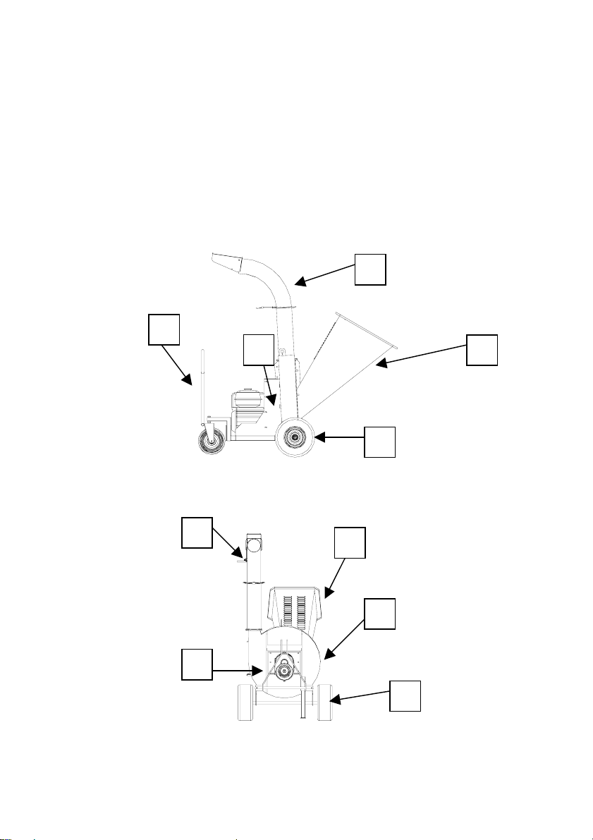
After checking that transport has been carried out correctly , proceed to
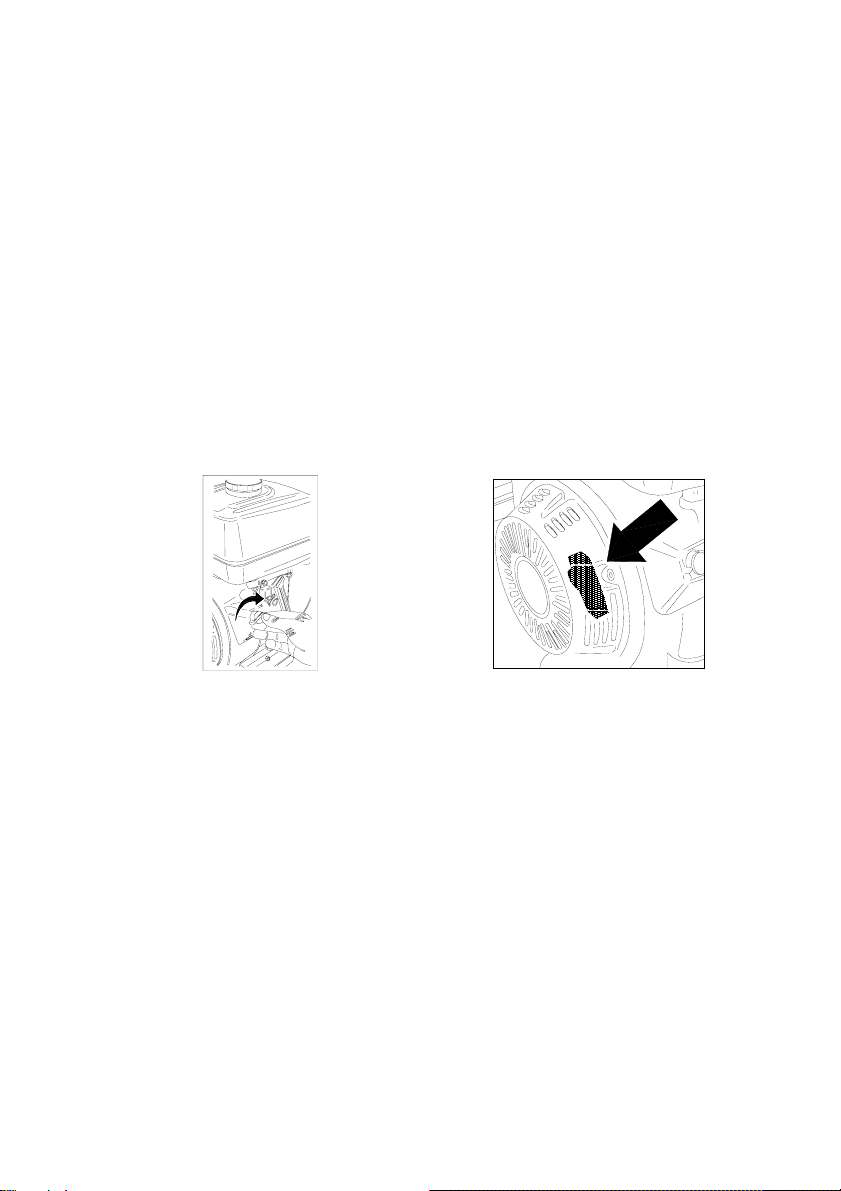
assembling the machine as shown in figures 4 - 5 .
• Activate the front wheel block and tighten the securing screws (Fig. 4).
• Mount the two rear wheels onto the axle and tighten the securing screws (Fig.
4).
• Mount the loading hopper and tighten the hinge screws (Fig. 5).

• Mount the unloading pipes and lock them in position using the screws provided
(Fig. 4).
Fig. 4
Fig. 5
Unloading pipes
Rear
wheel
Front wheel
assembly
Hopper
Hinge

5. TECHNICAL CHARACTERISTICS
The EC identification plate is clearly visible on the Bio 190 bio-
chopper ( fig. 6 ) .
In all communications with the manufacturer state the serial
number on the identification plate .
MACCHINE INDUSTRIALI
89/392
EN 292
EN 294
SERIAL No.
25037 PONTOGLIO (BS) - VIA M. ADAMELLO, 20
TELEF. 030 7470464 - FAX 030 7470004 - ITALY
Fig. 6
Version
Power HP / kw
Supply
Prod. m3 / h
BIO 190 B 13 / 9 Petrol 7/8*
BIO 190 E 10 / 7.5 Electric 380 V 7/8*
BIO 190 T 20 ÷30 / 14.9 ÷22.3 P.T.O. 7/8*
* data depending on quality of material to be chopped and feeding
speed
5.1 Overall dimensions
R=2,00mt
Breadth ( mm ) : 2000
Lenght ( mm ) : 1050
High ( mm ) : 2000
Weight ( kg. ) : ~ 300
LWA MAX ( dB ) : 104

6. SAFETY NORMS
Training
• The machine must not be used by under 16’s and persons who
have not learnt the user instructions .
• The operator is responsible for third parties present in the work
area . Keep children and domestic animals at distance when the
bio-chopper is in operation .
• This machine may be used only for cutting up natural wood and
foliage . It must not be used for other purposes ( e.g. for
breaking up bottles and boxes in other materials ) .
• Work only in adequate light .
• When you start up engine check that machine is equipped with
the prescribed guards .
• Wear protective gloves and goggles while working .
Preparation / Operation
• Before beginning work check that the blades and the cutters are
perfectly fixed. If the blades show signs of damage they should
be sharpened or replaced .
• Do not use the bio-chopper when it is raining .
• The bio-chopper must be positioned on a flat , solid surface
where there is no danger of overturning .
• Switch off the motor, remove the keys from the start panel and remove
the sparkplug cap ( the power supply cable for electric motor bio-
choppers , or check that the machine is disconnected from the
tractor PTO ) in order to :
- remove foreign bodies from the hoppers ;
- transport the machine or move it from the workplace ;
- carry out maintenance or cleaning ;
- leave the machine unattended .
• The blades continue to turn for a few seconds even after the
ignition has been switched off .
• Assemble the blades following the appropriate instructions and
use only original spare parts supplied by the manufacturer .
• Never use the chopper with defective guards and protection or
without the safety devices correctly fitted .
• Start up the engine with care and following the user instructions .
When the engine is functioning it is imperative to prevent anyone
from approaching the loading hopper , the discharger and the
side hopper .

• If the blades undergo heavy shock and function in an anomalous
manner , stop the engine , remove the spark plug hood and
request expert advice .
Caution ! The fuel is highly flammable :
• Keep fuel only in the containers made avaiable for this purpose ;
• Refuel only in the open air . Do not smoke or in any way cause
naked flames during refuelling .
• Fill the tank before starting the engine . Never open the fuel cap
or add petrol while the engine is running or when it is still hot .
• If petrol should be split , never try to start the engine . Move the
machine away from the area involved area and avoid any
sources of ignition until the fuel vapours have dispersed ;
• Tighten up the fuel tank cap .
Maintenance and storage
• Keep all nuts , bolts and screws perfectly tightened in order to
work in safe conditions .
• For safety reasons promptly replace worn or damage parts .
• To protect hands during dismantling and assembly of the blades ,
wear suitable protective gloves .
Version with electric motor
• Regularly check that the power supply cable is in perfect
condition . Never repair a damaged cable with insulating tape or
thermal clamps .
• For the power supply conductor use only standardised rubber
cable of the type 05 RN-F in accordance with DIN 57282 / VDE
0282 .
• Hook-up plugs must be in rubber or rubber covered .

7. START - UP
Caution ! Before starting up the engine / motor check that the bio-
chopper is on a stable surface and that there are no animals or
unauthorised persons in the work zone .
Read the engine / motor manufacturer’s instruction book carefully .
Check that there is oil and fuel in the tank . Fill if necessary .
Petrol engine version
• Put the selector at position “I” ( Start ) ( Fig. 8 ) . Grasp the
starting knob ( Fig. 10 ) and pull the cord without force until you
feel the resistance caused by compression , release the knob and
then give a sharp tug to start the engine .
• Before beginning work let the engine idle for about 1 minute
then take it to maximum revs ( using accelerator lever ) and
proceed with normal use .
0
1
Fig. 8 Fig. 9
Electric motor version
• Make sure the mains voltage corresponds to the motor rated voltage
(check the rating plate on the motor) .
• Check that the power supply cable is conected then press the
start / stop button .
Version with tractor coupling
• Make sure the cardan shaft connecting the bio-shredder and tractor is
in proper working order.
• Before each use, make sure the cardan shaft is in proper working order
.
• Check that the bio-chopper is correctly hooked up to the PTO
then proceed with starting .

Functioning
Having correctly prepared the bio-chopper you can now proceed to
working the material to be chopped .
Upper hopper
Load trimming and foliage into the upper loading hopper , taking
account of avaiable power in function of the model you possess ( fig.
10 ) .
MAX Ø 10 cm
Fig. 10
Caution ! Take the material to the hopper mouth and let it fall in .
Never put hands and arms in to push material into the hopper !
The material that can be worked and chopped in this hopper must
not exceed 10 cm diameter .
To avoid the danger of intoxication from fumes , machines with
internal combustion engines should never be used in closed
environments .

8. MAINTENANCE
Caution ! Before proceeding with any maintenance operation swith off
the engine / motor and in any case ensure that there is no possibility
of the machine functioning . Suitable gloves are obligatory for all
maintenance operations .
8.1 Blade replacement
• Unscrew the locking nuts and open the feed hopper.
• Unscrew the securing screws and remove the blades.
• Fit the new blades.
• Tighten the securing screws.
• Close the feed hopper and tighten the locking nuts.
Fig. 11
Chipping
blades

8.2 Counter-blade replacement
• Unscrew the locking nuts and open the feed hopper.
• Unscrew the 5 securing screws and remove the counter-blade.
• Replace the counter-blade with a new one.
• Tighten the securing screws.
• Close the feed hopper and tighten the locking nuts.
Fig. 12
Counterblade

8.3 Knives inversion and replacement
• Unscrew the locking nuts and open the feed hopper.
• Unscrew the 5 securing screws and remove the counter-blade.
• Unscrew the 6 screws and remove the front chipping disc.
• Remove the shaft , taking care to note the position of the
spacers separating the breaker bars .
• If necessary replace the breaker bars . Take care to replace the
previously removed spacers in the same position on the cutter
shaft .
• Pull out the knives and spacer rings, taking care to mark the position of
the rings between the knives.
• Remount the front chipping disc and lock the 6 securing screws in
position.
Caution ! Partial replacement of the breaker bars must be carried
out respecting the opposite position for balancing .
Fig. 13
Fig. 14
Sieve
Front chipper
disc
Knives
Spacers

8.4 Breaker bar removal , inversion and replacement
• Unscrew the locking nuts and open the feed hopper.
• Pull the sieve out of the grinding chamber.
• Insert a new sieve in the grinding chamber.
• Close the feed hopper and tighten the locking nuts.
Fig. 15
Sieve

8.5 Routine maintenance
Beginning
of season
Before
each job
End of
season
Check engine oil level
♦
Check screws , tightness ,
casing , hopper , etc .
♦
♦
Check belt tension and
state of wear
♦
♦
Check wear on cutters
♦
♦
Check wear on blade
♦
♦
Check wear on counter-
blade
♦
♦
Check hopper rubber
protection
♦
♦
♦
Clean machine
♦
Check wear on bearings
and transmission shafts
♦
♦

9. TROUBLESHOOTING - REMEDIES
Troubleshooting Remedies
The bio-chopper does
not start Check belt tension and condition , blocked
pulleys , PTO or gears .
Check cutters , blade , counter-blade and
presence of material in the milling chamber .
Check state of engine / motor ( consult the
instruction manual supplied ) .
Difficult start-up or
loss of power Check belt tension and condition , blocked
pulleys , PTO or gears .
Check state of engine / motor ( consult the
instruction manual supplied ) .
The bio-chopper
loses revs and
functions irregularly
Check belt tension and condition , blocked
pulleys , PTO or gears .
Check cutters , blade , counter-blade and
presence of material in the milling chamber .
Check the sieve which should be free of
blockages.
Check state of engine / motor ( consult the
instruction manual supplied ) .
Examine the material being chopped at the
moment of breakdown .
Excessive vibration Check cutters , blade , counter-blade and
presence of material in the milling chamber .
Drop in quality of
output material Check belt tension and condition , blocked
pulleys , PTO or gears .
Check state of engine / motor ( consult the
instruction manual supplied ) .
The hopper rejects
the material Check cutters , blade , counter-blade and
presence of material in the milling chamber .
Check state of engine / motor ( consult the
instruction manual supplied ) .
Check state of wear on hopper rubber
protection .

10. GUARANTEE
1. The Manufacturer hereby guarantees its BIO - SHREDDERS against
breakage caused by faulty materials or workmanship .
2. This warranty is valid for the first owner only for 12 months as from the
date of purchase and / or delivery .
3. The Manufacturer is entitled to inspect the Bio - Shredder and any
components for which a claim has been made under the guarantee , in
order to determine the validity of the claim .
4. This warranty covers replacements free of charge only of components
found to be defective due to faulty materials or workmanship under the
guarantee period.
5. This warranty does not cover reimbursement for labour , consumables or
transport charges for repairs under guarantee .
THIS WARRANTY DOES NOT APPLY IN THE FOLLOWING CASES
1. The Manufacturer may in no way held liable for general damage ,
including damage or injury , loss due to halts in production , loss of
earnings , leasing costs or any moral or commercial damage .
2. All claims concerning motors or engines mounted on Bio - Shredder will
be handled by the relevant Manufacturers’ after - sales service .
3. This warranty does not cover damage caused by misuse , abuse ,
insufficient maintenance , accident or damage caused during transport .
4. Parts which are subject to war , such as hammers , blades , anvil blades ,
etc . are not covered under this guarantee .
5. All expenses for setting the machine to work will be charged to the
distributor or dealer .
6. This warranty is not valid if the repairs , maintenance or modifications are
performed by an unauthorised persons or dealers .
7. The owner is responsible for routine maintenance and settings , which are
thus excluded herefrom .
8. The use or fitting or components and accessories that are not original
will immediately invalidate this warranty .
PROCEDURE FOR MAKING CLAIMS UNDER THIS WARRANTY
If the Bio - Shredder is found to be defective due to faults material or
workmanship, you are required to send the Manufacturer a written claim and
proceed as follows :
1. The machine must be returned to the Seller or the authorised
CARAVAGGI importer .
2. You are required to present the guarantee duly filled in or the bill , if this
is not avaiable.
3. The claim will be completed by the Dealer , who will forward it to the
Manufacturer .
4. The Manufacturer alone reserves the right to determine whether to accept
the claim or otherwise .
5. Any disputes will be put before the Court of Brescia ,
Italy .

11. DECLARATION OF CONFORMITY
The company Caravaggi , hereby declares under its own
responsability , that the machine BIO - SHREDDER Type Bio
190 electric , petrol and PTO versions , complies with the
Basic Safety and Health Requirements prescribed in EC
Directive 98/37, 89/336 and 73/23 and subsequent
modifications thereto 89/686 , 91/368 , 93/44 and 93/68.
EN 292
EN 294
The Manufacturer
( CARAVAGGI GIAN LORENZO )
Pontoglio , 01 / JAN / 1995

BIO 190 SPARE PARTS

BIO 190 SPARE PARTS
Pos. Description Q.ty Code
1 Driving shaft spacer 1 B19001001
2 Driving shaft 1 B19001002
3 Key 12x6x32 1 B19001003
4 Key 10x6x65 1 B19001004
5 Bearing 45x85x19 2 B19001005
6 Transmission flange 1 B19001006
7 Housing 1 B19001007
8 Straight outlet pipe 1 B19001008
9 Hopper hinge angle 1 B19001009
12 Cover 1 B19001012
13 Cover adjusting bar 1 B19001013
14 Wing nut M 8 1 B19001014
15 Elbow 1 B19001015
16 Hub 1 B19001016
17 Paddle-wheel 6 B19001017
18 Rear chipping disk 1 B19001018
19 Blade holder pin 6 B19001019
20 Spacer H = 6 6 B19001020
21 Spacer H = 12 18 B19001021
22 Central welding blade 1 B19001022
23 Hammer 24 B19001023
24 Front chipping disk 1 B19001024
25 Side chipping blade 2 B19001025
26 Screen 1 B19001026
27 Counterblade 2 B19001027
28 Hopper 1 B19001028
29 Hopper protection rubber 1 B19001029
30 Rubber fixing plate 1 B19001030
31 Set of adhesives 1 B19001031
32 Handle 25x8 1 B19001032
33 Spacer 3 B19001033
34 Spring handle 1 B19001034
35 Ring* 1 B19001035
*Optional item
This manual suits for next models
3
Table of contents
Other Caravaggi Chipper manuals