Carbide 3D Shapeoko Z-Plus User manual

support@carbide3d.com docs.carbide3d.com 8/26/2020 Version 1.0
2
Table of Contents
Introduction...................................................................................................................... 3
Inventory.......................................................................................................................... 4
Disconnect the BitSetter ................................................................................................... 7
Part 1: Disassembly........................................................................................................... 8
Disassemble the Existing X/Z-Carriage.............................................................................................. 8
Part 2: Assembly & Installation ....................................................................................... 11
Install the Drag Chain Support System............................................................................................ 15
Insert the Proximity Switch Cables into the Drag Chain.................................................................. 19
Install the Z-Plus .............................................................................................................................. 21
Install the Drag Chain...................................................................................................................... 23
Install the Proximity Switches.......................................................................................................... 25
Connect the Wiring.......................................................................................................................... 28
Cleanup the Cables.......................................................................................................................... 30
Part 3: Post Installation................................................................................................... 33
Tramming Instructions .................................................................................................................... 33
Update Your Machine Settings........................................................................................................ 35

support@carbide3d.com docs.carbide3d.com 8/26/2020 Version 1.0
3
Introduction
We’re here to help! If you encounter any issues during assembly, please contact us at: [email protected].
The Z-Plus kit includes everything you need to upgrade your existing X/Z-carriage to the Z-Plus (X/Z+). The Z-Plus kit also
includes new inductive proximity switches to replace the original homing switches. There are minor differences in the
installation procedures between Shapeoko 3, XL, and XXL models AND between Shapeoko models shipped pre-Dec 2019 and
post-Dec 2019. We’ve added special notes to guide you whenever these differences require alternate instructions:
Throughout the guide you will also find information that we’ve called out for you to pay particular attention to. We use
three types of call-outs, WARNINGS, NOTES, and PRO TIPS:
In this guide, any reference or instructions with regard to direction or placement, such as: Front, Back, Left, Right, etc. are
given from the perspective of one standing in front of and facing the machine. This is true, even when a photo is taken from
the rear of the machine.
IMPORTANT Software Information
Run Carbide Motion 4.17 or later with the Z-Plus. Download Carbide Motion: carbide3d.com/carbidemotion/download
Assembly Requirements
To carry out this upgrade, you need basic mechanical skills and an understanding of how the Shapeoko is assembled.
Installation takes approximately 2 hours.
Required tools:
•Metric hex keys: 1.5mm –6mm
•Wrenches: 8mm and 10mm
•Needle nose pliers
•Permanent marker
•Tape measure or ruler
•Scissors
•Flush cut pliers
•Masking tape
WARNING: After installing the Z-Plus, you must update your GRBL settings. DO NOT HOME UNTIL YOUR SETTINGS
HAVE BEEN UPDATED!
SPECIAL INSTRUCTIONS: These call-outs will draw your attention to special instructions for different models.
WARNING: This is a warning—pay close attention. Information in these boxes is very important.
NOTE: This is a note—information that points out critical steps or information for future reference.
PRO TIP: This is a pro tip—helpful additional information.

support@carbide3d.com docs.carbide3d.com 8/26/2020 Version 1.0
4
Inventory
Z-Plus Upgrade Kit Contents
The Z-Plus upgrade comes with the components listed in the table below and shown in Fig. 1.
Item
Description
Qty
A
X/Z+ Carriage (Z-Plus)
1
B
M5 × 10mm Socket Head Cap Screw
4
C
Tramming Plate
1
D
M5 × 8mm Socket Head Cap Screw
4
Figure 1

support@carbide3d.com docs.carbide3d.com 8/26/2020 Version 1.0
5
Proximity Switch Cable Kit
E
X-Axis Proximity Switch (2675mm for XXL, 2350mm for XL, and 712mm for Shapeoko 3)
1
F
Y-Axis Proximity Switch (2540mm for XXL, 2200mm for XL, and 610mm for Shapeoko 3)
1
G
Z-Axis Proximity Switch (200mm for XXL, 200mm for XL, and 610mm for Shapeoko 3)
1
H
Z-Axis Proximity Switch Extension Cable (2438mm for XXL, 2235mm for XL,
no extension for Shapeoko 3)
1
I
PCB Riser Board
1
Proximity Switch Mounting Kit
J
X-Axis Proximity Switch Mount
1
K
Y-Axis Proximity Switch Mount
1
L
M5 × 25mm Socket Head Cap Screw
2
M
M5 × 35mm Socket Head Cap Screw
2
N
M3 × 18mm Socket Head Cap Screw
6
Drag Chain Support Bracket Kit
O
X-Axis Drag Chain Head Bracket
1
P
Y-Axis Drag Chain Head Bracket
1
Q
Middle Support Bracket [Used with Post-Dec 2019 Extrusion Rails Only]
3
R
Tail Support Bracket [Used with Post-Dec 2019 Extrusion Rails Only]
2
S
M5 Nut
2
T
M5 × 16mm Socket Head Cap Screw
2
U
M5 × 8mm Socket Head Cap Screw
2
V
M4 × 6mm Socket Head Cap Screw [Used with Post-Dec 2019 Extrusion Rails Only]
10
W
M3 × 4mm Flat Head Cap Screw [Used with Post-Dec 2019 Extrusion Rails Only]
6
Drag Chain Support Plate Kit [Used with Pre-Dec 2019 Extrusion Rails Only]
X
Middle Support Plate
2
Y
Tail Support Plate
2
Z
M3 × 4mm Flat Head Cap Screw
2
AA
Alcohol Wipes
2
BB
Double-Sided VHB Tape
2
Cable Tie Cleanup Kit [Used with Post-Dec 2019 Extrusion Rails Only]
CC
Cable Tie Mount
5
DD
M4 × 6mm Button Head Cap Screw
5
EE
Cable Ties
100

support@carbide3d.com docs.carbide3d.com 8/26/2020 Version 1.0
6
Shapeoko Carryover Components
The Z-Plus upgrade requires several parts from the existing machine. All components and hardware to be carried over
are listed in the table below and shown in Fig. 2. Throughout this guide, carryover parts will be called out by the
words: CARRY OVER.
Item
Description
Qty
FF
Drag Chain
1
GG
X-Rail Belt and Hardware: Belt Clip (1) and M5 × 10mm Socket Head Cap Screw (1)
3
HH
X-Motor
1
II
Spindle/Router Mount
1
JJ
M5 × 16mm Button Head Cap Screw
2
KK
Router Mount Adapter Ring (Optional)
1
Figure 2
NOTE: Please use the replacement screws provided in the Z-Plus Kit.

support@carbide3d.com docs.carbide3d.com 8/26/2020 Version 1.0
7
Disconnect the BitSetter
Before beginning the Z-Plus upgrade:
1. Connect your machine to Carbide Motion.
a. Plug in your USB cable.
b. Open Carbide Motion.
c. Turn on your Shapeoko.
d. Click the Connect to Cutter button.
2. Click Settings in the top menu bar.
3. If you have the BitSetter checkbox checked, go ahead and uncheck it.
You will need to re-setup your BitSetter after successful homing with your new Z-Plus.
Machines With BitSetter: Please complete the following steps before moving on to Disassembly on page 8.

support@carbide3d.com docs.carbide3d.com 8/26/2020 Version 1.0
8
Part 1: Disassembly
Disassemble the Existing X/Z-Carriage
Disconnect Cables and the X-Axis Belt
1. Turn off your machine, unplug it, and disconnect the USB and power cables.
2. Clip all cable ties.
3. Unplug the router/spindle and remove it from the spindle mount.
a. Use a 4mm hex key to loosen the two (2) M5×55mm SHCS on the face of the mount.
b. If you are using the adapter ring: loosen the router mount, slide the router up, then lift the adapter
ring to free it from the mount.
4. Free the Y2-end of the X-Axis belt from the Y2-carriage. (No need to remove the Y1-end.)
a. Use a 4mm hex key to remove the M5×10mm SHCS securing the belt clip.
b. Remove the clip from the end of the belt and pull the belt free from the X-motor pulley and idlers.
c. CARRY OVER the belt,belt clip, and M5×10mm SHCS.
5. Label all motor lead cables AND their extension cables.
a. Use a permanent marker or piece of tape to label all the white male/female connectors of the X-, Y1-,
Y2-, and Z-stepper motor lead cables AND the X-, Y1-, Y2-, and Z-stepper motor extension cables.
6. Disconnect all cables.
a. Remove the Carbide Motion board enclosure cover.
b. Disconnect the X-, Y1-, Y2-, and Z-motor leads from their extension cables AND disconnect all
extension cables and homing switches from the Carbide Motion board.
NOTE: As you complete the disassembly process, you may find it helpful to keep each CARRY OVER component
and its associated hardware together and away from the new Z-Plus parts to avoid any mix ups.
WARNING: Do NOT disconnect motor connectors by pulling on the wires or by prying at the latch. Use pliers to
gently grip the base of each white connector and pull apart.

support@carbide3d.com docs.carbide3d.com 8/26/2020 Version 1.0
9
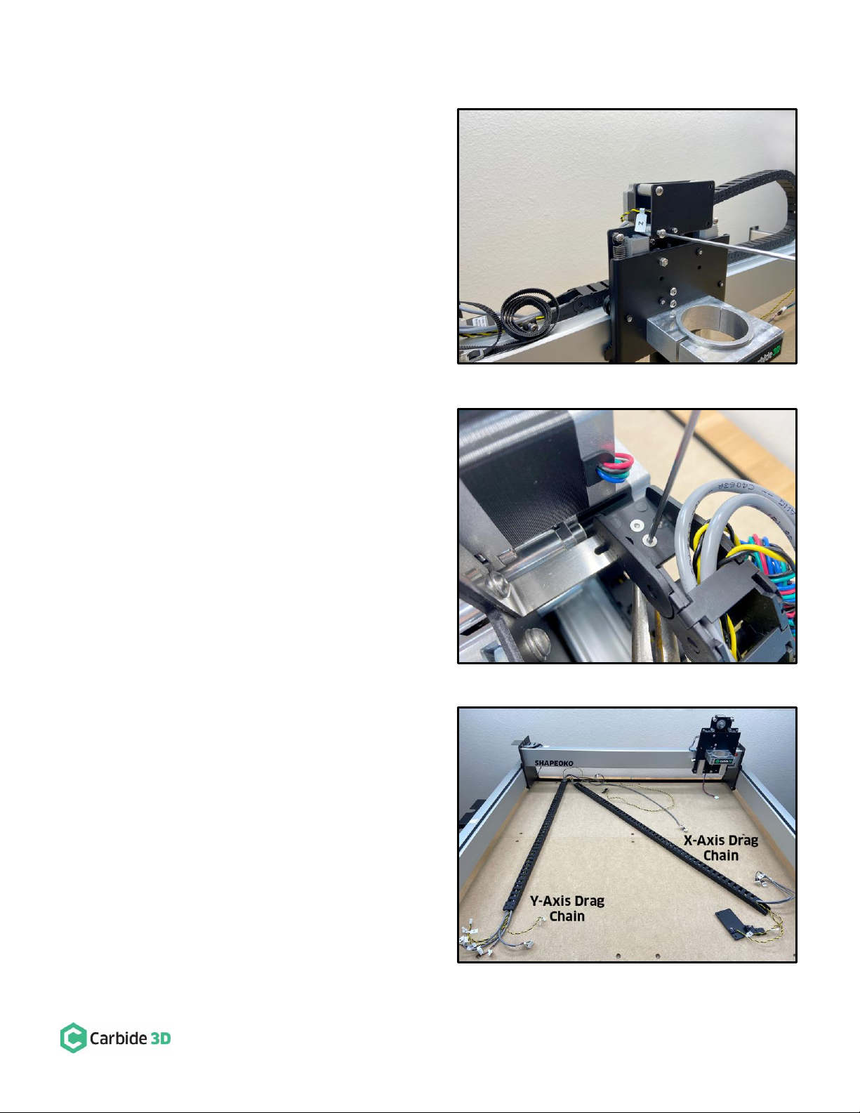
Remove the Homing Switches, Drag Chain, and X/Z-Carriage
1. Remove the Z-Axis homing switch plate from the
front of the X/Z-carriage. See Fig. 3.
a. Use a 3mm hex key to remove the four (4)
M5×10mm BHCS securing the plate. (No
need to separate any of the switches from
their mounting plates.)
2. Remove the X-Axis homing switch plate from the
rear of the X/Z-carriage.
a. Use a 4mm hex key to remove the two (2)
M5×35mm SHCS and two (2) 1-inch
spacers.
3. Remove the Y-Axis homing switch plate from the
outside of the Y2-carriage.
a. Use a 4mm hex key to remove the two (2)
M5×35mm SHCS and two (2) 1-inch
spacers.
4. Disconnect the X-Axis drag chain from the X-Axis
head bracket on the rear of the X/Z-carriage. See
Fig. 4.
a. Use a 2mm hex key and needle nose pliers
to remove the two (2) M3×8mm FHS and
two (2) nylon lock nuts securing the drag
chain to the head bracket.
5. Disconnect the Y-Axis drag chain from the Y-Axis
head bracket on the outside of the Y1-carriage.
a. Use a 2mm hex key and needle nose pliers
to remove the two (2) M3×8mm FHS and
two (2) nylon lock nuts securing the drag
chain to the head bracket.
6. Remove the drag chain from the rails and lay it on
the baseframe as shown in Fig. 5.
a. Pry the tail ends of the drag chain from
the VHB tape securing them to the rails.
b. Remove the VHB tape from the rails.
c. CARRY OVER the drag chain.
7. Remove the Y-Axis drag chain head bracket from
the outside of the Y1-carriage.
Figure 3
Figure 4
Figure 5

support@carbide3d.com docs.carbide3d.com 8/26/2020 Version 1.0
10
a. Use an 8mm wrench and a 4mm hex key to remove the two (2) M5 nuts and two (2) M5×16mm SHCS.
8. Remove the lower two V-wheels from the X/Z-carriage.
a. Hold the eccentric nuts steady with an 8mm wrench and use a 3mm hex key to remove the V-wheels.
9. Lift the X/Z-carriage away from the X-rail and lay it on the baseframe.
Disassemble the X/Z-Carriage
1. Separate the Z-carriage from the X-carriage. Fig. 6.
a. Remove the springs from both sides of the
X/Z-carriage.
b. Loosen the tensioning screw at the
bottom of the X-carriage plate.
i. Use a 3mm hex key to loosen the
tensioning screw.
c. Loosen the idler assembly at the bottom
of the X-carriage and free the belt.
ii. Use a 4mm hex key and a 10mm
wrench to loosen the nut holding
the idler in place.
iii. Free the belt from the idler and
the Z-motor pulley.
d. Slide the smaller Z-carriage down and
away from the larger X-carriage.
2. Remove the router/spindle mount from the
Z-carriage plate.
b. Use a 3mm hex key to remove the two
M5×16mm BHCS securing the mount.
c. CARRY OVER the router/spindle mount
and M5×16mm BHCS.
3. Remove the X-motor (lower motor) from the back
of the X-carriage plate.
d. Use a 4mm hex key to remove the four
M5×10mm SHCS securing the motor.
e. CARRY OVER the X-motor.
Figure 6
WARNING: Do not mix up the X- and Z-motors. The orientation of the X-motor’s drive pulley on the drive shaft
is very important for Z-Plus assembly. See Fig. 7.
Figure 7

support@carbide3d.com docs.carbide3d.com 8/26/2020 Version 1.0
11
Part 2: Assembly & Installation
Assembly Tips
We recommend assembling as much of the Z-Plus as possible before installing it onto the Shapeoko; this process is
described in the steps below.
Get Familiar with the Z-Plus
1. Take a minute to familiarize yourself with the front and back of the Z-Plus. See Fig. 8.
Figure 8
NOTE: The application of a blue (i.e. light/medium grade) thread locker is at your discretion. We suggest adding
it post-assembly if any screws happen to work their way loose during use.

support@carbide3d.com docs.carbide3d.com 8/26/2020 Version 1.0
12
Assemble the Z-Plus —Back
Z-Plus Upgrade Kit + Carryover Components:
Item
Description
Qty
B
M5 ×10mm Socket Head Cap Screw
4
J
X-Axis Proximity Switch Mount
1
L
M5 ×25mm Socket Head Cap Screw
2
O
X-Axis Drag Chain Bracket
1
U
M5 ×8mm Socket Head Cap Screw
2
HH
X-Motor [CARRYOVER]
1
1. Install the X-Axis drag chain head bracket (long,
narrow head bracket) on the rear of the Z-Plus.
See Fig. 9.
a. Align bracket with the M5 screw holes at
the top of the Z-Plus, flange down.
b. Use a 3mm hex key and two (2) M5×8mm
SHCS to secure.
2. Install the X-Axis proximity switch mount. See
Fig. 9 and Fig. 9 inset.
a. Align the mount with the two M5 holes
next to the X-motor standoffs.
b. Use a 4mm hex key and two (2)
M5×25mm SHCS to secure. There are
outer and inner screw slots in the mount;
use the OUTER screw slots.
3. Remove the lower two V-wheels. See Fig. 9.
a. Use a 4mm hex key and 10mm wrench to
remove the M5×25mm SHCS, V-wheels,
and M5 washers (shims). Set them aside.
4. Install the X-motor. See Fig. 10.
a. Align the X-motor with the four (4)
standoffs, Carbide 3D label facing down
toward the idlers.
b. Use a 4mm hex key and four (4)
M5×10mm SHCS to secure the X-motor.
Figure 9
Figure 10
Shapeoko 3 Machines: Skip installation of the X-Axis
drag chain head bracket (#1 below).

support@carbide3d.com docs.carbide3d.com 8/26/2020 Version 1.0
13
Assemble the Z-Plus —Front
Z-Plus Upgrade Kit + Carryover Components:
Item
Description
Qty
C
Tramming Plate
1
D
M5 ×8mm Socket Head Cap Screw
4
G
Z-Axis Proximity Switch (200mm XXL, 200mm XL, and 610mm Shapeoko 3)
1
N
M3 ×18mm Socket Head Cap Screw
2
II
Spindle/Router Mount [CARRYOVER]
1
JJ
M5 ×16mm Button Head Cap Screw [CARRYOVER]
2
KK
Router Mount Adapter Ring (Optional) [CARRYOVER]
1
The tramming plate is a feature of the Z-Plus which
allows you to easily adjust left/right tilt of the
router/spindle. The tramming plate’s four mounting
holes are slightly enlarged providing a small amount of
wiggle room around the screws and allowing you to
tram your router/spindle in relation to the X-Axis. See
Fig. 11.
Install the Spindle/Router Mount to the
Tramming Plate
1. Attach the spindle/router mount to the
tramming plate. See Fig. 12.
a. Position the tramming plate with the
larger notch at the top.
b. Align the router mount with the two
available screw holes across the
center of the plate.
c. Use a 3mm hex key and the two (2)
M5×16mm BHCS to secure the mount
to the plate.
Figure 12
Figure 11
NOTE: See Tramming Instructions at the end of
this guide for more information on tramming.

support@carbide3d.com docs.carbide3d.com 8/26/2020 Version 1.0
14
Install the Tramming Plate to the Z-Plus
1. Install the tramming plate to the front of the
Z-Plus. See Fig. 13.
a. Align the tramming plate with the four
available M5 holes.
b. Use a 4mm hex key and four (4) M5×8mm
SHCS to secure.
2. Install the router mount adapter ring if you have a
65mm router.
Install the Z-Axis Proximity Switch to the Z-Plus
1. Install the Z-Axis proximity switch to the front of
the Z-Plus. See Fig. 14.
a. Check to make sure the leadscrew stopper, the silver cylinder at the bottom of the leadscrew, is
present and tighten if necessary.
b. With both hands grasp the sides of the
Z-Plus and, slowly but firmly, lower the
Z-carriage with your thumbs until it stops
at the bottom.
c. Insert the Z-Axis proximity switch cable
through the hole at the top of the Z-Plus,
just under the Z-motor.
d. Position the proximity switch with the red
LED facing front and the target pointing down.
e. Align the proximity switch’s mounting slots with the two M3 holes at the top of the Z-Plus.
f. Use a 2.5mm hex key and two (2) M3×18mm SHCS to secure the proximity switch.
i. Before fully tightening the screws, slide the switch up as far as it will go.
Figure 13
NOTE: If the leadscrew stopper is missing from
your Z-Plus, please stop the assembly process here
and contact us at support@carbide3d.com. If you
continue with the assembly process, you could
damage your Z-Plus.
Figure 14

support@carbide3d.com docs.carbide3d.com 8/26/2020 Version 1.0
15
Install the Drag Chain Support System
Install the Y-Axis Head Bracket
Z-Plus Upgrade Kit:
Item
Description
Qty
P
Y-Axis Drag Chain Head Bracket
1
S
M5 Nut
2
T
M5 ×16mm Socket Head Cap Screws
2
1. Install the Y-Axis drag chain head bracket to the
outside of the Y1-carriage. See Fig. 15.
a. Use a 4mm hex key and two (2)
M5×16mm SHCS to attach the head
bracket to the Y1-carriage plate.
b. Use an 8mm wrench and two (2) M5
nuts to secure the bracket, flange down,
to the M5x16mm SHCS.
Identify Your Extrusion Rail Version
1. Examine your X- and Y1-Rails. You will have
either:
•Pre-Dec 2019 extrusion rails. See Fig. 16.
oX-Rail: No screw holes.
oY1-Rail: Two M5 threaded screw holes in
the center.
Figure 15
Figure 16
Shapeoko 3 Machines: Skip ahead to the “Install the Z-Plus” section on page 21.
Pre-Dec 2019 Rails: Your setup may look slightly
different than the setup pictured in this document.

support@carbide3d.com docs.carbide3d.com 8/26/2020 Version 1.0
16
•Post-Dec 2019 extrusion rails. See Fig. 17.
oX-Rail: Sixteen M4 threaded screw holes.
oY1-Rail: Two M5 threaded screw holes on
the left-side of the rail and four M4
threaded screw holes along the top of the
rail.
Install Drag Chain Supports
Install the Drag Chain Support Plates [Pre-Dec 2019 Rails ONLY]
Z-Plus Upgrade Kit:
Item
Description
Qty
X
Drag Chain Middle Support Plate
2
Y
Drag Chain Tail Support Plate
2
AA
Alcohol Wipe
2
BB
Double-Sided VHB Tape
2
Drag chain support plates install onto the top of the rail with the long edge perpendicular to the rail. The short edge of
the plate lines up with the rail’s centerline, allowing the plate to overhang the back side of the rail by 1”. The PEM nuts
in the drag chain tail support plates overhang the rail.
Figure 17
Pre-Dec 2019 Rails: You will need to install the four (4) included drag chain support PLATES. Complete the
instructions in “Install the Drag Chain Support Plates” below.
Post-Dec 2019 Rails: You will need to install the five (5) included drag chain support BRACKETS. Skip ahead to
“Install the Drag Chain Support Brackets” on page 18.

support@carbide3d.com docs.carbide3d.com 8/26/2020 Version 1.0
17
1. Attach one (1) middle support plate and one (1)
tail support plate onto the X-rail. See Fig. 18
(image from rear).
a. Measure and mark 5” and 19 ½” from the
Y1-carriage.
b. Clean support plates AND rail, on the far
side (Y2-side) of each mark, with an
alcohol wipe.
c. Cut a piece of double-sided VHB tape in
half.
d. Stick both tape halves to the top of the
rail, to the far side of each mark, between
the centerline and back of the rail.
e. Stick the middle support plate (no PEM
nut) to the tape at the 19 ½” mark.
f. Stick the tail support plate (with PEM nut) to the tape at the 5” mark. Orient the plate with the PEM
nut overhanging and toward the Y1-side of the rail.
g. Press each plate firmly to the rail for 30 seconds.
2. Attach one (1) middle support plate and one (1) tail support plate onto the Y1-rail. See Fig. 18.
a. Measure and mark 7 ½” and 16 ½” from the front endplate.
b. Clean support plates AND rail, on the far side (rear-endplate-side) of each mark with an alcohol wipe.
c. Cut the remaining piece of double-sided VHB tape in half.
d. Stick both tape halves to the top of the rail, to the far side of each mark, between the centerline and
outside of the rail.
e. Stick the middle support plate (no PEM nut) to the tape at the 7 ½” mark.
f. Stick the tail support plate (with PEM nut) to the tape at the 16 ½” mark. Orient the plate with the
PEM nut overhanging and toward the front endplate.
g. Press each plate firmly to the rail for 30 seconds.
Figure 18

support@carbide3d.com docs.carbide3d.com 8/26/2020 Version 1.0
18
Install the Drag Chain Support Brackets [Post-Dec 2019 Rails ONLY]
Z-Plus Upgrade Kit:
Item
Description
Qty
Q
Drag Chain Middle Support Bracket
3
R
Drag Chain Tail Support Bracket
2
V
M4 ×6mm Socket Head Cap Screw
10
Drag chain support brackets install flange down to the
horizontal sets of M4 screw holes on the extrusion rails.
The top of the bracket sits flush with the top of the rail.
1. Install two (2) middle support brackets (no PEM
nut) and one (1) tail bracket (with PEM nut) to the
back side of the X-rail. See Fig. 19 (image from
rear).
a. Install the tail bracket to the set of M4
holes closest to the Y1-carriage.
b. Use a 3mm hex key and two (2) M4×6mm
SCHS to secure each support bracket to
the rear of the X-rail.
2. Install one (1) middle support bracket (no PEM
nut) and one (1) tail bracket (with PEM nut) to the
outside of the Y1-rail. See Fig. 19 (image from
rear).
a. Install the tail bracket to the set of M4 holes closest to the Carbide Motion board enclosure.
b. Use a 3mm hex key and two (2) M4×6mm SCHS to secure each support bracket to the outside of the
Y1-rail.
Figure 19

support@carbide3d.com docs.carbide3d.com 8/26/2020 Version 1.0
19
Insert the Proximity Switch Cables into the Drag Chain
Install the Proximity Switch Cables
Z-Plus Upgrade Kit:
Item
Description
Qty
E
X-Axis Proximity Switch Cable (2675mm XXL and 2350mm XL)
1
F
Y-Axis Proximity Switch Cable (2540mm XXL and 2200mm XL)
1
H
Z-Axis Proximity Switch Extension Cable (2438mm XXL, 2235mm XL)
1
1. Open up the drag chain and remove the homing
switch cables. See Fig. 20 and Fig. 21.
a. Position the drag chain on the baseframe
as shown in Fig. 21, with the chain’s clip-on
panels facing up. (Only one side of the
chain will open; be sure this side is facing
up.)
b. Use a hex key or screw driver as a lever to
pry open one side of each drag chain link.
Start from the rear of the machine and
work your way forward (as shown in
Fig. 20).
c. Remove the three black and yellow X-, Y-,
and Z-Axis homing switch cables.
2. Label the proximity switches AND gray 3-pin
extension cable.
a. Identify the X- and Y-Axis proximity
switches by comparing the length printed
on the switch body with the table above.
b. Use a permanent marker or piece of tape
to label the white female connectors of
X- and Y-Axis proximity switch cables AND
the gray Z-Axis proximity switch extension
cable.
Figure 21
Figure 20

support@carbide3d.com docs.carbide3d.com 8/26/2020 Version 1.0
20
3. Insert the proximity switches and extension cable
into the drag chain. See Fig. 22.
a. Insert the X-Axis proximity switch cable
and the gray Z-Axis proximity switch
extension cable through both the Y-Axis
and X-Axis portions of the drag chain.
b. Insert the Y-Axis proximity switch cable
through the Y-Axis drag chain ONLY.
4. Close up the drag chain. Do not install onto the
rails just yet.
Figure 22
NOTE: Position the female end of the gray Z-Axis
proximity extension cable at the tail of Y-Axis drag
chain.
Table of contents
Other Carbide 3D Power Tools manuals