6
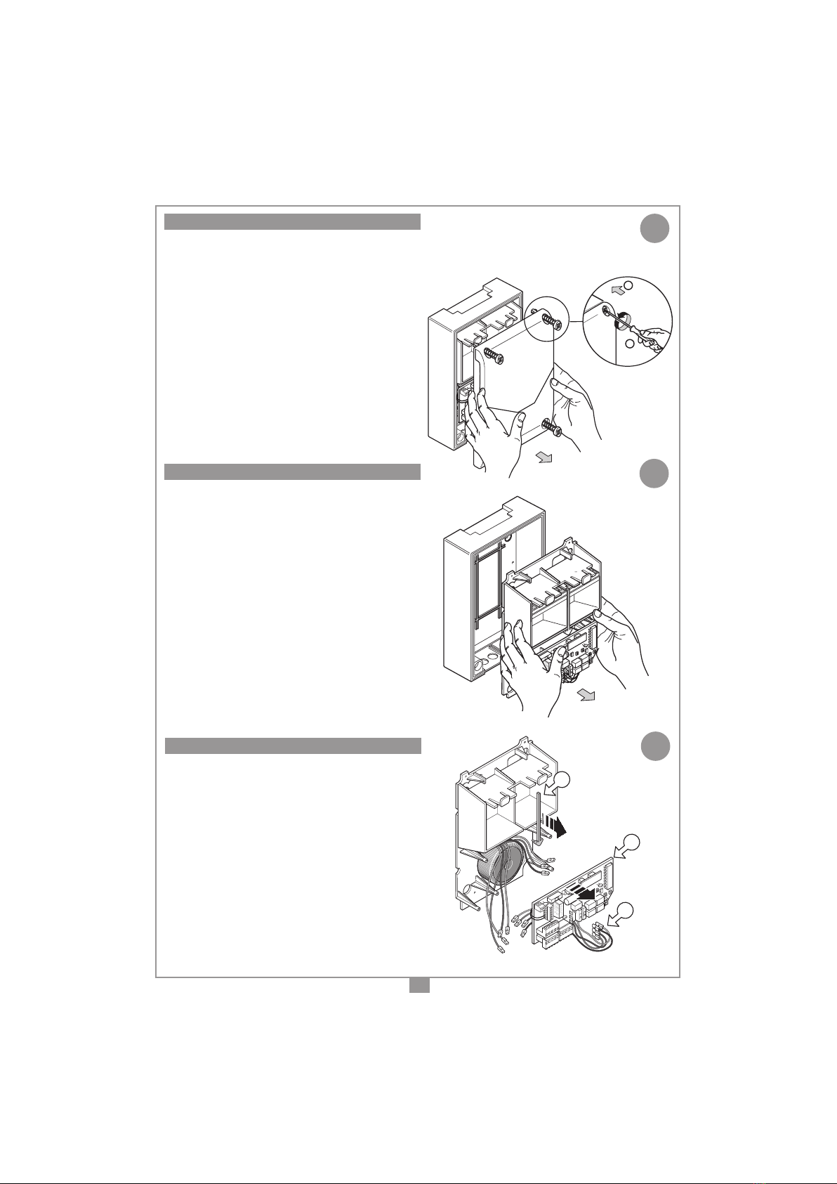
• Collegare i quattro li (muniti di faston)
provenienti dal circuito carica batterie
al circuito della centralina "M" (vedi g.
6-7).
• Inlare i cavi con cura dentro lo spazio
rimasto tra le due batterie "N", tenendo
piùinaltoilicollegatialtrasformatore.
• Reinserire il circuito "Q" nel contenitore
essarloconleappositeviti.Fareatten-
zionecheiliprovenientidalcarica-bat-
terie arrivino ai Faston del programmatore
passandogli sotto.
• Reinserireilcopricavo"P".
• Reinserireilbloccoportabatterie/scheda
essarloconleappositeviti.
• Rimettereilcoperchio.
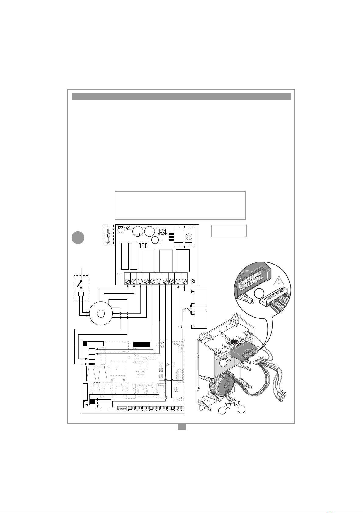
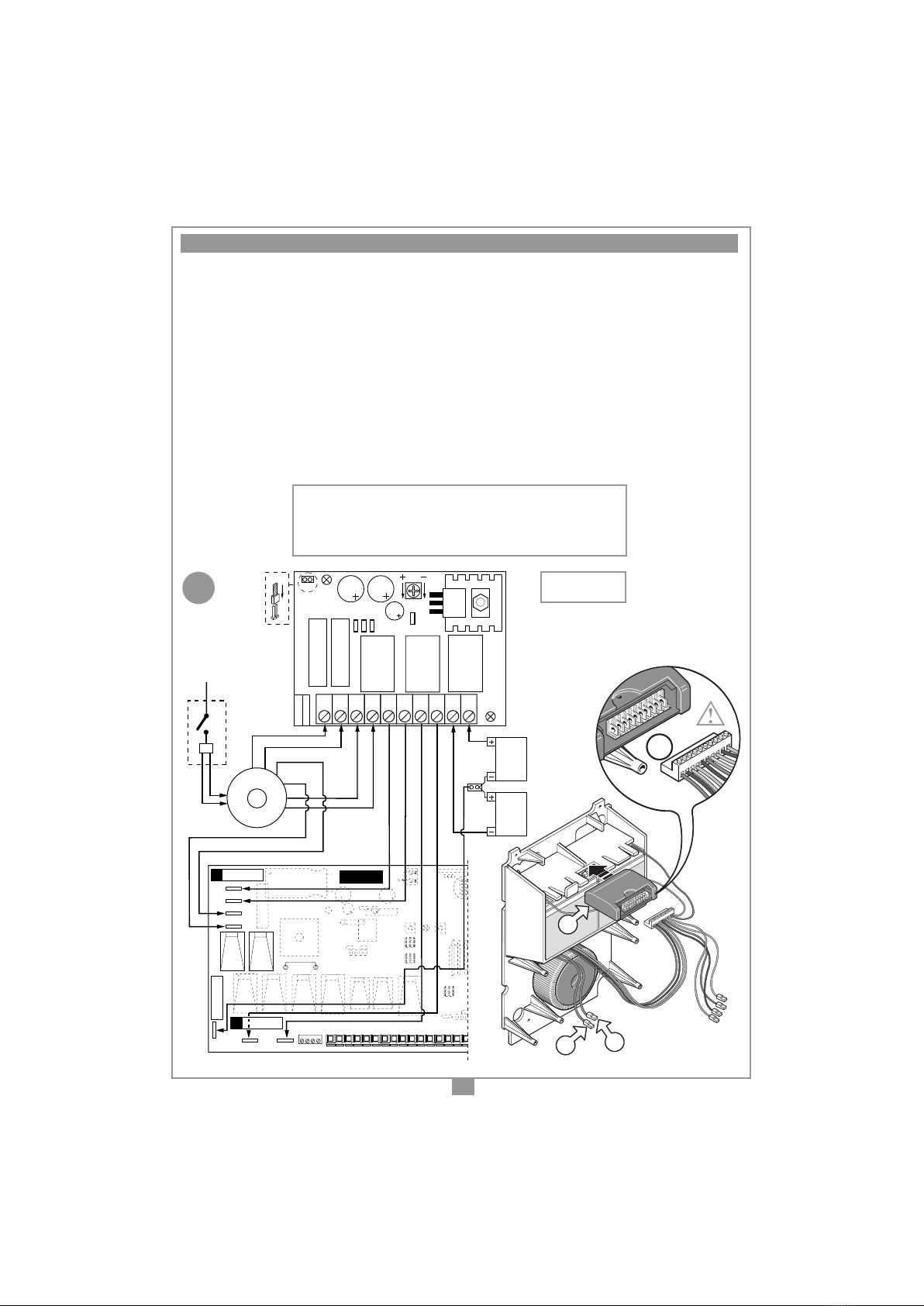
Quando la tensione di rete è presente, i relé del caricabatterie sono normalmente eccitati e i due
secondari del trasformatore vengono direttamente collegati ai faston della centralina. In assenza della
tensione di rete, i relé tornano alla condizione di riposo, e la tensione di batteria viene applicata alla
centralina,siaperquantoriguardalapartelogicacheperquelladicontrollodelmotore.
LED di segnalazione del circuito carica-batterie (g.6-7)
L1:accesoquandolabatteriaècollegatacorrettamente(conjumper"J1" inserito).
L2:accesoquandolacorrenteerogatadalcarica-batterieèsuperioreallacorrentedimantenimento
della batteria (60 mA circa per una batteria da 4 Ah): Batterie in fase di carica.
Protezione contro l’inversione della polarità batteria
Sulcircuitocarica-batterieèmessounfusibile"F4"aprotezionedellabatteria,perevitarechel’in-
versionepossadanneggiarla; selasicollega in modoerratoedil carica-batterie èalimentatoda
rete,ilfusibile"F4"salteràassiemealfusibilediprotezionedelcircuitomotore"F3"sullaschedadi
controllo motore.
Utilizzo di batterie di tipo differente
L’utilizzo di batterie diverseda quelle forniteèfattosotto la completa responsabilità dell’installa-
tore, in particolare riguardo ad un errato posizionamento delle stesse (non conforme alle normative
vigenti). È possibile adattare il carica-batterie ad un altro tipo di batteria regolando la tensione di
caricain uscita agendo sul trimmer"P1" (g. 6-7): la tensionein uscita, da misurarea vuoto sui
morsetti 9-10, è impostata in Fabbrica:
- 27 Vdc per un utilizzo con 2 batterie in serie da 12 Vdc (4 Ah).
Autonomia del sistema
L'autonomiadelsistemaquandoèalimentatoabatteriaèstrettamentelegataallecondizioniambien-
tali (temperatura), ed al carico connesso sull'uscita a 24 V della centralina (che anche in caso di
caduta di corrente risulta sempre alimentato). Nel caso l'assenza di rete a 230 V duri più di 10 ore,
ricordarsiditogliereilfusibile"F2"(protezionesulcircuitodialimentazionelogica,soloperPRG851)
dalla scheda di comando motore, in modo da scollegare la batteria dal circuito. In caso contrario
labatteriapotràscaricarsieccessivamenteealterarelesuecaratteristichediefcienza(laricarica
successiva potrebbe essere fatta solo in modo limitato).
Attenzione!Vericarechelaconnessionedeimorsetti7e8airelativifastondellacentralina
(g.6-7)siacorretta:invertendolaconnessionelacentralinarisultanonalimentata.
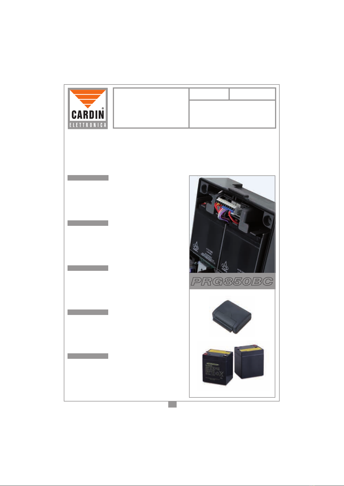
Montaggio CARICA BATTERIA
PRG851
02-02-2000
DM0477 Description :
Product Code :
Date :
Drawing number :
P.J.Heath
CARDIN ELETTRONICA S.p.A - 31020 San Vendemiano (TV) Italy - via Raffaello, 36 Tel: 0438/401818 Fax: 0438/401831
Draft :
All rights reserved. Unauthorised copying or use of the information contained in this document is punishable by law
FIG.6 (senza contenitore)
Q
MODALITÀ DI FUNZIONAMENTO
ASSEMBLAGGIO FINALE
MODALITÀ DI FUNZIONAMENTO
8