IVAC® Volumetric Pump (Models 571 & 572) 10/104 1000SM00018 Issue 2
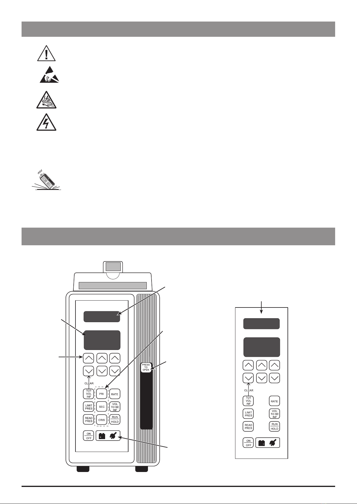
Introduction and Start Up
Changing the infusion rate
1. Press the RUN/HOLD switch to place the pump on hold.
2. Press the RATE switch.
3. Use the JK switches to set the new rate.
4. Restart the pump at the new rate by pressing the RUN/
HOLD switch.
Clearing the total Volume Infused
1. Press the RUN/HOLD switch to place the pump on hold.
2. Press and hold the TOT VOL INF switch and the K
switch directly above simultaneously for 2 seconds until
display shows 000.0.
3. Resume infusion by pressing the RUN/HOLD switch.
Changing the Volume To Be Infused
1. Press the RUN/HOLD switch to place the pump on hold.
2. Press the VOL TO BE INF switch.
3. Set new volume by pressing the JK switches. OFF can
also be selected when a flow sensor is in use, see Notes
below.
4. Restart the pump by pressing the RUN/HOLD switch.
Notes:
1) Without a flow sensor in use, a VTBI value must be entered,
otherwise, the pump will be unable to operate.
2) With a flow sensor in use, a VTBI value isn't required and
OFF can be selected if required.
Programming
Adjusting the maximum pressure limit
(Occlusion pressure alarm level)
1. Simultaneously press and hold the LIMIT PRES
switch whilst using the JK switches to adjust
the pressure limit.
2. Release the LIMIT PRES switch.
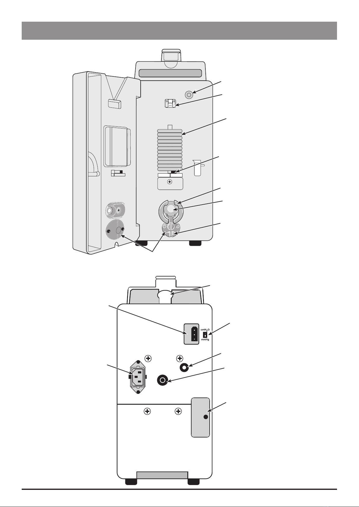
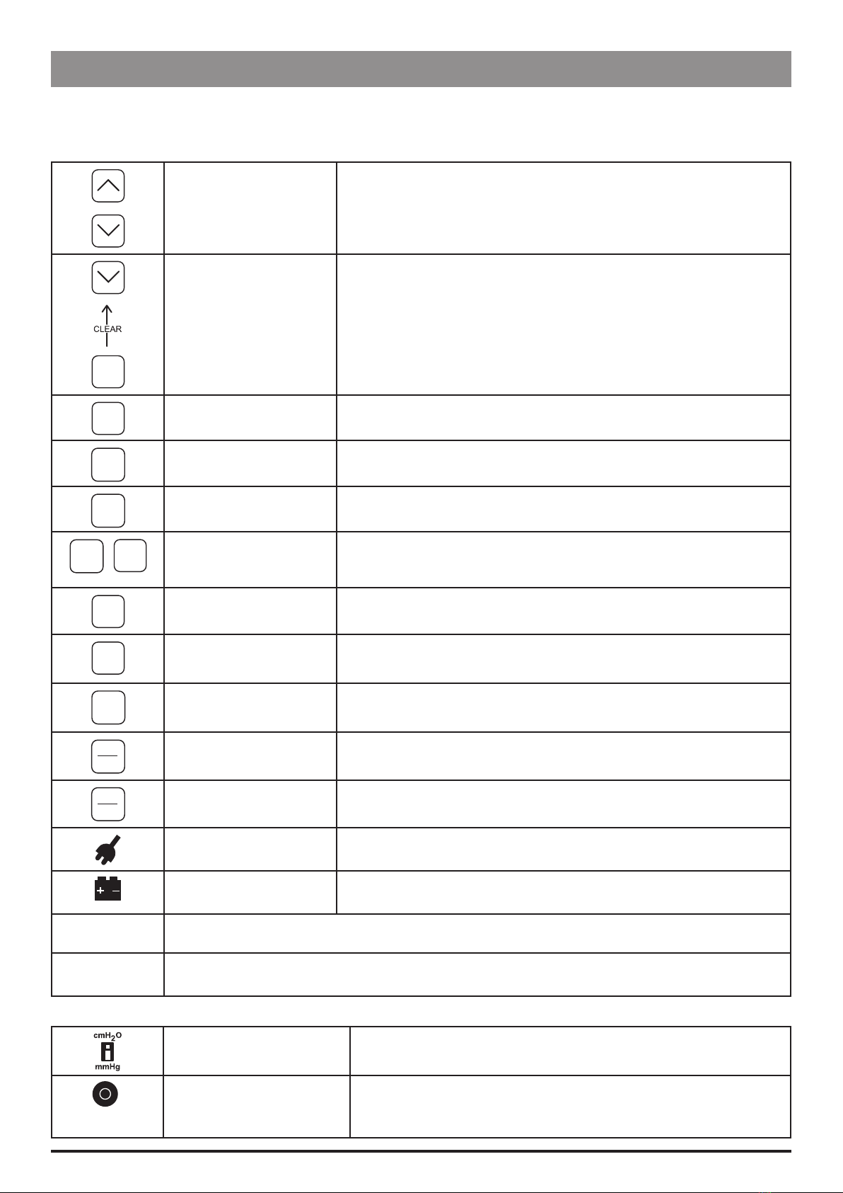
Note: Pressure value will be displayed in mmHg or in
cmH20 depending on unit selected. See 'Pressure
Unit Selector'.
Reading the pressure
1. Press and hold the READ PRES switch. Wait at least
10 seconds to allow reading to stabilize.
Note: Pressure value will be displayed in mmHg or
in cmH20 depending on unit selected. See 'Pressure
Unit Selector'.
Selecting alternating display of total
volume infused
1. Press and release the TOT VOL INF switch three
times within 2 seconds while the pump is infusing or
on hold.
On Model 572, the display will alternate between
primary or secondary infusion and total volume
infused.
On Model 571, the display will continuously
show the total volume infused.
Selecting alternating display of infusion
pressure
1. Press and release the READ PRES switch three times
within 2 seconds while the pump is infusing or on
hold.
On Model 572, the display will alternate between
primary or secondary infusion and infusion
pressure.
On Model 571, the display will continuously
show the infusion pressure.
Operating on Battery Power
The pump operates on battery power when it is disconnected from the AC power. The battery power indicator, the
Information and Numeric Displays will flash whenever the pump is on battery power. In the event of a power failure, the
pump will automatically continue to operate on battery power.
Two alarms indicate the condition of the pump's battery:
LOW BATT alternating with the selected volume or pressure status. This indicates that approximately 30 minutes of
operating time remains on battery power
LOW BATT (constant). This indicates that the battery is discharged. Connect the pump to an AC power supply to
recharge the battery.
Note: The pump's battery is designed for limited duration use. Wherever possible, the pump should be used connected
to an AC power supply. If the pump is to be taken out of service for an extended period, it is good practice to charge the
battery periodically to ensure full capacity.