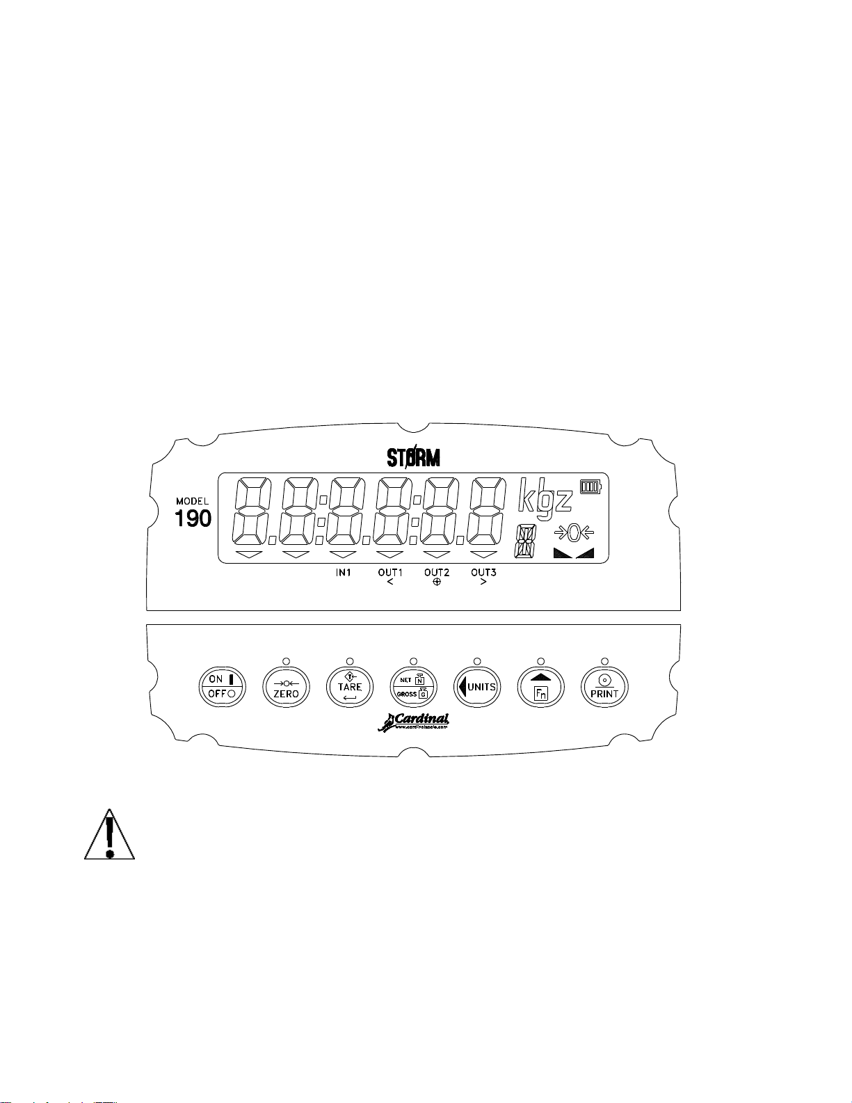
Cardinal Priefert 190P Specification sheet

Page 1
Priefert 190P
Digital Weight Indicator
Quick Set Up

Page 2

Page 1
Unpack
Unpack the box and check that you have each of the following:
190P Digital Weight Indicator
Data Cable (PN: 3502-B476-0A)
Cable Gland (PN: 6610-2248)
Mounting Gimbal (PN: 8400-C004-08)
Rubber Feet (x4) (PN: 6540-1004)
Manual on CD (PN: 8400-M022-01)
Charge Battery
To charge the battery pack, plug-in the power cord to an AC power outlet. It will take
approximately six (6) hours to fully recharge the battery pack in the indicator. The
indicator may be operated while the battery is charging.
The battery status indicator indicates the level of charge. When
charging the battery, the charge level status bars will scroll.

Page 2
OPERATION
The following sections give a quick overview of the 190P indicator and its operation.
For detailed information please refer to the 190 Installation, Technical and Operation
Manual (PN: 8400-M022-01) on the CD received with the indicator.
Keypad and Display
The Model 190 uses a capacitive touch keypad that requires a “finger
touch” to function. The keypad will not operate with other items such as
pen, pencil or tools.

Page 3
Key
Description
ON/OFF: The ON/OFF key is used to turn the
indicator on and off.
Press the ON/OFF key when the indicator is
off to turn the indicator ON. The 190 will
perform a display test (turn on all segments)
and then show the model number and
software version.
If the indicator is already on, press the
ON/OFF key and hold for 2 to 3 seconds.
When the display shows OFF, release the
key to turn the indicator OFF.
ZERO: The ZERO key is used to zero the weight
display. Up to the selected limit of 4% or 100%
of the scale’s capacity can be zeroed. This limit
is selected during the setup and calibration of the
indicator.
Note that the indicator will not respond to
pressing the ZERO key unless the weight display
is stable.
When displaying a Tare weight, pressing
the ZERO key will clear the Tare value and
set the display to Gross mode.
When displaying the Peak weight, pressing
the ZERO key will clear the Peak weight.
When displaying the Gross accumulator,
pressing the ZERO key will clear the Gross
accumulator.
When displaying the Net accumulator,
pressing the ZERO key will clear the Net
accumulator.

Page 4
Key
Description
TARE(Enter): The TAREkey is used during
normal operation to store the current Gross weight as
the new Tare weight. The display will change to the Net
weight and the Net annunciator will turn on.
Pressing the TAREkey when in the Net weight
mode will cause the display to show the Tare
weight.
During Setup, pressing the TAREkey will
display the current setting of the parameter.
Pressing the TAREkey a second time (after
changing parameter values or settings), signals
completion of the entry of data and causes the
indicator to process the data entered.
NET/GROSS: The NET/GROSS key is used to toggle
between the Gross and Net weight modes. The
selected mode is indicated by turning on the appropriate
annunciator on the display.
Note that if no valid tare weight has been entered,
pressing the NET/GROSS key will cause a momentary
display error (notArE) and the indicator will remain in
the Gross weight mode.
When in Hold, Count, Peak weight, Live weight, or
Accumulator display mode, press the NET/GROSS key
to return the display to normal weight display mode.
UNITS/(Left Arrow): The UNITS/key is used for
several functions.
In normal operation, the UNITS/key is used to
select the units in which the weight is to be
displayed. The available units of measure ("unit1",
“unit2” and "unit3") are selected in setup. The
available units include pounds, ounces, kilograms,
and grams.
During setup, the UNITS/key is used to advance the
cursor left to the next position when inputting setup
parameters.

Page 5
Key
Description
Fn/(Up Arrow): The Fn/key is used for
several functions.
During indicator setup, when a setup
parameter (not a parameter value or setting)
is displayed, pressing the Fn/key will
"backup" to the previous parameter prompt.
Also during setup, when a parameter value
or setting is displayed, pressing the Fn/
key will "toggle" between the different
available values or settings for that
parameter.
In normal operation, the Fn/key is used in
conjunction with the other keys on the keypad to
access additional indicator features.
PRINT: Pressing the PRINT key during a
weighing operation, will add the displayed Gross
weight, or Net weight to the associated
accumulator and send print ticket data to the
serial interface selected during setup (see
Port=).
NOTE: The indicator will not respond to
pressing the PRINT key unless the weight
display is stable.
If displaying Gross weight, the only weight
printed is Gross weight.
If displaying Net weight, the Gross, Tare,
and Net weights are printed.
When in Gross weight accumulator display
mode, pressing the PRINT key will print the
Gross weight accumulator.
When in Net weight accumulator display
mode, pressing the PRINT key will print the
Net weight accumulator.
When in Peak weight display mode,
pressing the PRINT key will print the Peak
weight.

Page 6
Fn/Key Functions
The Fn/key is used to select several additional functions that may have
been enabled during the setup and calibration of the indicator. Those
functions include: Hold, Count, Time and Date, Peak Hold, Checkweigher,
Live Weight, Weight Accumulation and Backlight Color.
IMPORTANT! The Hold, Count and Live Weight functions cannot
be enabled if the Legal-For-Trade option (LFt=yes) was selected
during setup.
In addition, only one of the functions Hold, Count, Peak Hold,
Checkweigher or Live Weight can be enabled at a time.
Description of Fn/Key Functions
Function
Display
Description or Setting
Hold
HoLd X
X will be 1 if enabled, 0 if disabled
Count
CoUnt X
X will be 1 if enabled, 0 if disabled
Time and Date
HH:MM A
HH=hours, MM=minutes,
A for AM, P for PM
MM.DD.YY
(usa=yes)
DD.MM.YY
(usa=no)
MM=month, DD=day, YY=last two
digits of year
Peak Hold
PhoLd X
X will be 1 if enabled, 0 if disabled
Checkweigher
Lo=
Minimum acceptable weight prompt
X*
= minimum acceptable weight value.
* When the value for Lo= is greater
than 0, the Checkweigher function
is enabled.
Hi=
Maximum acceptable weight prompt.
This prompt is displayed, when the
value for Lo= is greater than 0.
X
= maximum acceptable weight value
Live Weight
Act X
X will be 1 if enabled, 0 if disabled
Weight
Accumulation
ACCU X
X will be 1 if enabled, 0 if disabled
Backlight Color
Colors
Backlight Colors for normal operation
and Checkweigher results

Page 7
Annunciators
The Model 190 is equipped with annunciators that are turned on to
indicate that the display is in the mode corresponding to the annunciator
label or that the status indicated by the label is active. This section
describes each annunciator. Refer to Figure No. 13 for the location of the
annunciators.
Symbol
Name
Description
0
ZERO
This annunciator is turned on to
indicate that the weight displayed is
within ± 1/4 division of true zero.
STABLE
This annunciator is turned on when
the weight display is stable. When
off, it means that the change in
successive weight samples is
greater than the motion limits
selected during setup.
N
NET
This annunciator is turned on when
the displayed weight is Net weight
(Gross weight less Tare weight).
G
GROSS
This annunciator is turned on to
show that gross weight is displayed.
Gross weight will be displayed when
no tare weight is stored.
T
TARE
This annunciator is turned on to
show that the displayed weight is the
tare weight.
lb
pounds
This annunciator is located to the
right of the weight display and is
turned on to show that the displayed
weight unit is pounds.
oz
ounces
This annunciator is located to the
right of the weight display and is
turned on to show that the displayed
weight unit is ounces.

Page 8
kg
kilograms
This annunciator is located to
the right of the weight display
and is used to indicate that
the displayed unit of weight
measurement is kilograms.
g
grams
This annunciator is located to
the right of the weight display
and is used to indicate that
the displayed unit of weight
measurement is grams.
C
COUNT
This annunciator shows that
the display is in the Count
mode and the value displayed
is in pieces (the count
quantity) and not weight.
G and A
or
N and A
ACCUMULATOR
This annunciator shows that
the displayed value is the
content of the accumulator.
IN1
DIGITAL INPUT
This annunciator is used to
signal that a remote key
function has been activated.
Note that this annunciator is
active only when the Digital
Input feature has been
enabled. Refer to the d in
parameter in Setup.
OUT1
UNDER
This annunciator is used to
signal that the displayed
weight is less than the
minimum value of acceptable
weight used in the
Checkweigher feature or that
preset 1 is active.
Note that this annunciator is
active only when the
Checkweigher feature or the
preset feature has been
enabled. Refer to the d oUt
parameter in Setup.

Page 9
OUT2
ACCEPT
This annunciator is used to signal
that the displayed weight is within
the acceptable weight limits for the
Checkweigher feature.
That is, the weight is equal to or
greater than the minimum
acceptable weight and equal to or
less than the maximum acceptable
weight.
This annunciator is also used to
indicate that preset 2 is active.
Note that this annunciator is active
only when the Checkweigher feature
or the preset feature has been
enabled. Refer to the d oUt
parameter in Setup.
OUT3
OVER
This annunciator is used to signal
that the displayed weight is equal
to or greater than the minimum
value of overweight used in the
Checkweigher feature
This annunciator is also used to
indicate that preset 3 is active.
Note that this annunciator is active
only when the Checkweigher feature
or the preset feature has been
enabled. Refer to the d oUt
parameter in Setup.

Page 10
SETUP REVIEW
The 190 indicator allows several operational parameters to be reviewed
and changed without breaking the calibration seal.
Accessing Setup Review
1. With the indicator ON, press Fn/key and then the ZERO key.
2. The display will change to show td= (the prompt for selection of a
12 or 24 hour clock).
3. Press the TAREkey to show the current setting. If the setting
displayed is acceptable, press the TAREkey again to save it.
Otherwise, use the Fn/key to toggle to a new setting and then
press the TAREkey to save it and advance to the next prompt.
4. To exit Setup Review, press the TAREkey to step through the
remaining prompts OR at any time, cycle the power (press the
ON/OFF key twice).
Td=
Time and Date (Select 12 or 24 hour clock)
d in=
Digital Input (Disable or Select key function)
d out=
Digital Output (Disable or Select Preset/Checkweigher
function)
SLEEP=
Sleep Mode (Disable or Select number of minutes
before entering sleep mode)
A off=
Auto Shutoff (Disable or Select number of minutes
before automatic shutoff)
toUCH=
Key Touch Sensitivity (Select number of milliseconds
key must be touched before key press is acted upon)
Sio?
Serial Input/Output Configuration
(Select YES or NO)
baUd=
Select Serial Port Baud Rate
prty=
Select Serial Port Parity
Cont1=
Enable or Disable Continuous Output to the Serial Port
type=
If Cont1=YES
(Select Continuous Output Format, SMA or Cardinal
Scoreboard)

Page 11
print?
Print Tab Settings Configuration (Select YES or NO)
port=
Disable or Select Serial Interface for Printing
HoUr=
Time Print Location
date=
Date Print Location
gross=
Gross Weight Print Location
tare=
Tare Weight Print Location
net=
Net Weight Print Location
g aCC=
Gross Weight Accumulator Print Location
n aCC=
Net Weight Accumulator Print Location
CoUnt=
Count "number of pieces on the scale" Print Location
EACH=
Piece Weight Print Location
CRLF=
Carriage Return Line Feed (Data Format Termination)
EoP=
End-Of-Print Line Feeds
opt?
Options Configuration (Select YES or NO)
opt=
Select Option Card Installed
baUd=
Select Option Card Baud Rate when Opt= 0 or 1
Prty=
Select Option Card Parity when Opt= 0 or 1
Cont2=
Enable or Disable Continuous Output to the Option Port
type=
If Opt=1 and Cont2=YES
(Select Continuous Output Format, SMA or Cardinal
Scoreboard)
baUd=
Select Field Bus Option Baud Rate when Opt= 2
Addr=
Select Field Bus Option MAC Address when Opt= 2
Color?
Display Backlight Color Setup (Select YES or NO)
dflt=
Select Default Backlight Color
Under=
Select Checkweigher “Under“ Backlight Color
ACCPt=
Select Checkweigher “Accept“ Backlight Color
oEr=
Select Checkweigher “Over“ Backlight Color

Page 12
Ticket Format Selection
The 190 includes support for visual tickets. Visual tickets are designed
by the PC based programs Visual Print or nControl and then downloaded
to the indicator.
The 190 allows one programmable format in addition to the standard
print tab settings format.
1. Press the Fn/key then the PRINT key.
2. The display will change to show Prt=.
3. Press the TAREkey to show the current value.
4. If the setting displayed is acceptable, press the TAREkey again
to save it.
5. Otherwise, press the Fn/key to "toggle" between the different
available settings and then press the TAREkey to save it.
Allowable settings are:
0 = print tab settings
1 = visual ticket format
NOTE: When a print format is selected, it will remain active
until changed by the operator.
TICKET EXAMPLE
10:19 08/23/2013
100.00 lb G
20.00 lb T
80.00 lb N
0.00 lb GROSS ACCUM
272.00 lb NET ACCUM

Page 13
Time and Date Functions
With the Time and Date function enabled during setup of the indicator,
the function must be activated before it can be used.
Refer to section 4.14 Function Setup, the FUnC (FUnC?) parameter to
enable the Fn/key Time and Date function.
NOTE: With USA=yes, the date format is month-day-year. If USA=no,
the date format is day-month-year.
Set the Time
1. Press and hold the Fn/key until the display blanks.
2. Once the display blanks, release the Fn/key
3. Press the TAREkey until the display shows the time prompt,
HH:MM X. Note that X will be A for AM or P for PM.
4. If the time displayed is correct, press the TAREkey to save it.
5. Otherwise, press the Fn/key to toggle between A and P.
6. Next, press the UNITS/key to select the digit of the minutes or hour
to change.
7. Press the Fn/key to change the digit's value.
8. When the correct time is displayed, press the TAREkey to save it.
9. Repeatedly press the TAREkey to step through the remaining
function prompts until the indicator returns to the weight display.
Set the Date
1. Press and hold the Fn/key until the display blanks.
2. Once the display blanks, release the Fn/key.
3. Press the TAREkey until the display shows the date prompt.
4. If the date displayed is correct, press the TAREkey to save it.
5. Otherwise, use the UNITS/key to select the digit of the month, day
or year to change and then use the Fn/key to change the digit's
value.
6. When the correct date is displayed, press the TAREkey to save it.
7. Repeatedly press the TAREkey to step through the remaining
function prompts until the indicator returns to the weight display.

Page 14
Checkweigher
The Model 190 indicator has logic level outputs that can be used to
control peripheral devices used to signal when the weight is within preset
limits. The output state of the Checkweigher (before reaching the preset
weight) is defined in section 4.4 SETUP, the d out= (Digital Output)
parameter. Note that these outputs are at logic level and cannot drive
external devices directly. Solid-state relays can be used to accept the
logic level outputs from the 190 and in turn, drive the external device.
With the Checkweigher function enabled during setup of the indicator,
the function must be activated before it can be used.
Refer to section 4.14 Function Setup, the FUnC (FUnC?) parameter to
enable the Fn/key Hold function.
NOTE: Only one of the functions Hold, Count, Peak Hold, Checkweigher
or Live Weight can be active at a time.
Target Weight Setup
1. Press and hold the Fn/key until the display blanks.
2. Once the display blanks, release the Fn/key
3. The display will change to show the first function prompt.
4. Repeatedly press the TAREkey until the Lo 1= prompt is
displayed.
5. Press the TAREkey once again.
6. The display will show the current value for the minimum acceptable
weight for ID 1.
7. If the setting displayed is acceptable, press the TAREkey to save
it.
8. Otherwise, use the Fn/and UNITS/keys to enter a new value for
the minimum acceptable weight for ID 1.
9. When the desired weight value is displayed, press the TAREkey
to save it.

Page 15
10. The display will change to show the Hi 1= prompt.
11. Press the TARE key again.
12. The display will show the current value for the maximum
acceptable weight for ID 1.
13. If the setting displayed is acceptable, press the TARE key to
save it.
14. Otherwise, use the Fn/▲key and UNITS/◄key to enter a new
value for the maximum acceptable weight for ID 1.
15. When the desired value is displayed, press the TARE key to
save it.
16. The display will change to show the Lo 2= prompt.
17. Repeat steps 5-9 above to set the value for the minimum
acceptable weight for ID 2.
18. The display will change to show the Hi 2= prompt.
19. Repeat steps 11-15 above to set the value for the maximum
acceptable weight for ID 2.
20. Continue to enter minimum and maximum acceptable weights
for the remaining ID’s for up to ten (10) ID’s, or press the
UNITS/◄key at the Lo n= prompt or the Hi n= prompt to
skip the entry of the remaining weights.
21. Repeatedly press the TARE key to step through the remaining
function prompts until the indicator returns to the weight
display.
22. Note that if low weight for ID 1 is set to 0, the checkweigher
function will be disabled. The low and high weights must be
less than scale capacity and the high weight must be greater
than the low weight.

Page 16
Target Weight Selection
1. From the weight display, briefly press and then release the Fn/▲key.
2. The display will show the prompt id=.
3. Press the TARE key.
4. The display will show the ID of the currently selected target weight.
5. If the setting displayed is acceptable, press the TARE key to save it.
6. Otherwise, use the Fn/▲ key to enter a new value for the ID.
7. When the desired value is displayed, press the TARE key to save it.
8. The indicator will return to the weight display.
Checkweigher Operation
With the Checkweigher function enabled and activated, during operation
the indicator will compare the displayed weight with the preset values
and display the results as under, accept, or over.
When the displayed weight is less than the minimum acceptable weight,
the arrow over OUT1 < (the UNDER annunciator) will turn on and the
display will change to the color selected in section 4.15, Display
Backlight Color Setup.
When the displayed weight is greater than the maximum acceptable
weight, the arrow over OUT3 > (the OVER annunciator) will turn on
and the display will change to the color selected in section 4.15,
Display Backlight Color Setup.
When the displayed weight is within the range from minimum acceptable
weight to maximum acceptable weight, the arrow over OUT2 (the
ACCEPT annunciator) will turn on and the display will change to the
color selected in section 4.15, Display Backlight Color Setup.

Page 17

Page 18
8400-0154-0M 06/15
Table of contents
Other Cardinal Accessories manuals

Cardinal
Cardinal 210 User manual

Cardinal
Cardinal 185 User manual

Cardinal
Cardinal 225 User manual

Cardinal
Cardinal SMARTCELL 825D User manual

Cardinal
Cardinal 210-FE User manual

Cardinal
Cardinal 205 User manual

Cardinal
Cardinal 825 User manual

Cardinal
Cardinal Detecto 750C Manual instruction

Cardinal
Cardinal 748P User manual

Cardinal
Cardinal 748 User manual

Cardinal
Cardinal 210 User manual

Cardinal
Cardinal 220 User manual

Cardinal
Cardinal 204 User manual

Cardinal
Cardinal CN20 Series User manual

Cardinal
Cardinal 758 User manual

Cardinal
Cardinal 225D SmartCell User manual

Cardinal
Cardinal 204 User manual

Cardinal
Cardinal 210 User manual

Cardinal
Cardinal 205 User manual

Cardinal
Cardinal 200 User manual