Carefree 1050 Technical specifications

1
Installation and programming instructions
Owner's Manual
Now standard 2 Relay's with automatic voltage
Detector 10 to 30 volts AC or DC

2
Introduction
Carefree Security self-contained keypads are fully sealed and are ideal for adverse environment conditions due to the
electronics being potted in an epoxy, making the keypad impervious to water and moisture.
Carefree Security keypads are a digital keyless entry system designed for access control applications. The keypad is housed in a
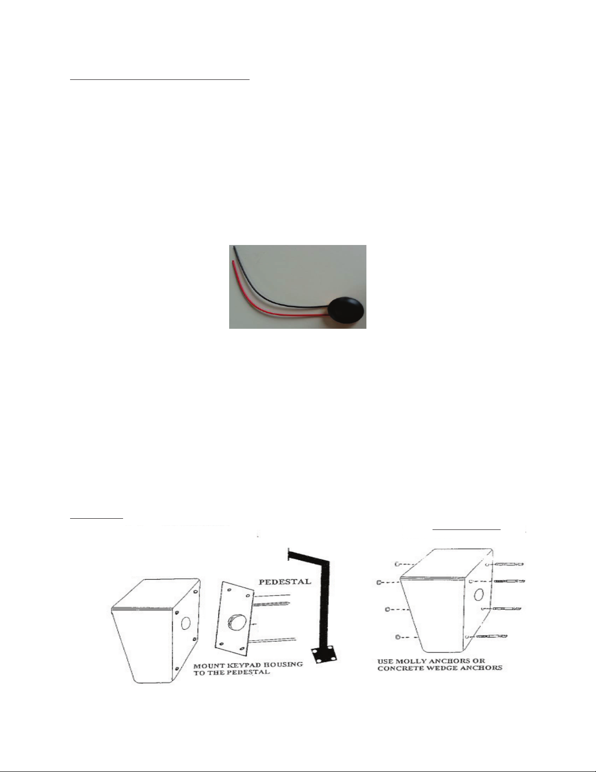
metal powder coated enclosure that can be mounted to a pedestal or directly to a wall. The keypad is available in two versions,
heavy duty metal die cast keyboard or with a heavy duty plastic polymer keyboard. The keyboards have bright, easy to read
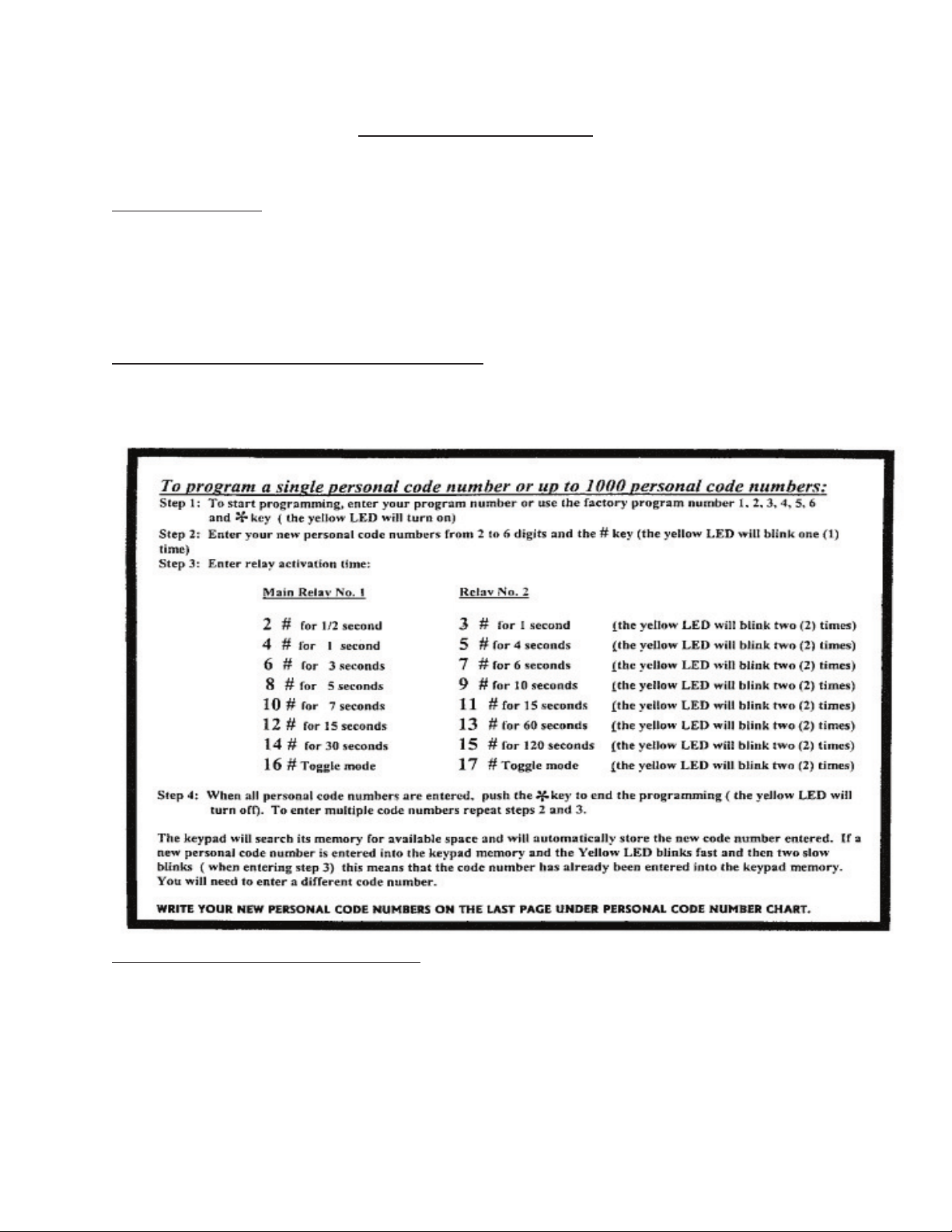
graphics. Single or up to 1000 entry codes (PIN) from 2 to 6 digits in length, can be programmed.
Two LED indicators show the status of the keypad system. The red LED indicates power on, green LED indicates access is
granted, yellow program LED light indicates that the keypad is in program mode or in a “lockout” condition. The keypad night
light illuminates the keys to a brighter state for the duration of If wrong number is entered during programming, pressing the *
key will end programming. Entering your code number, an internal sounder beeps when a key is pressed.
IMPORTANT- PLEASE NOTE
Please read all instructions before installing or programing this keypad. It is very important to apply and follow the procedures
described herein. Your keypad represents a new generation of keypad technology that is simple to use and operate.
TECHNICAL NOTES:
·The user of the keypad has up to 30 seconds to key in their entry code.
·All digits of the personal code number must be entered followed by # key. If the # key is not pressed, with correct
code entry, activation will be sent within ½ second after the last correct access code / digit is pressed.
·To avoid ESD (electrostatic discharge) interfering with the operation of the keypad, ground the housing.
·Lightning and Surge Protection is built into the keypad. However, if you install a keypad in an area where lightning can
damage the keypad, make sure to install a Model 306, Lightning & Surge Protector for extra protection. There is no
warranty if the keypad is damaged by lightning, static electricity or high voltage surges.
·The keypad has automatic voltage sensor from 10 to 30 volts AC or DC. Current 10 mA typical, 150 mA maximum.
·Output Relay #1, Form C, 5 Amp, Relay #2, Form C, 1 Amp.
·The keypad has a built in timer for remote exit, a door exit switch can be wired form the keypad to a N.O. push button
exit switch or to a fire access key switch to provide “codeless” entry for authorized personnel.
·When pressing any number on the keypad it will activate the Night Light to a brighter state for the duration of
entering your code numbers.
·Latching relay code (toggle mode) to hold gates or doors open.
·Too many incorrect code number entries, will cause a lockout condition and the yellow LED will blink
FEATURES:
·Programmable Keypad
·Up to 1000 Personal Code Numbers
·2 to 6 digital entry code length
·Microprocessor based memory
·Lightning and Surge protection built in
·2 LED status indicators
·Audio tone buzzer, shipped standard with feature but not required. Can be ordered without feature.
·Easy to program
·Built in timer for remote exit door switch or fire access key switch
·Latching Relay to hold gates or doors open
·Rugged Heavy Duty Metal Housing
·Powered from a 10 Volt to 30 Volt AC or DC source
·Highly vandal resistant
·Fully sealed metal push button or plastic keyboard
·No code number loss with power failure (EPROM MEMORY)
·Night light illuminates keys whenever keypad is used
·Timed anti-pass back; and keypad lockout

3
Warning
All illustrations and operating instructions should be read before the unit is connected to power and operated. The
installation and operating instructions should be retained for future reference. All operating and user instructions
should be followed. The housing should be mounted to a wall or as recommended by the manufacturer. The unit
should be connected to a power supply only of the type described in the operating instructions or as marked on
the unit. Regular testing by entering any valid Personal Code Numbers must be done to ensure proper operation.
Make sure that all necessary requirements, such as the proper placing of operating, warning and safety signs are
followed in accordance with all Local, State and Federal regulations to ensure the safety and wellbeing of all those
within the area of operation of this unit. Install this unit only on a gate or door operator with an automatic force
reverse action.
Typical Installation:
Red LED light (on left) shows power on and turns to
GREEN
when access is granted.
Yellow LED light will
be on during programming and in keypad lockout.
.mode.
If a wrong key is entered, press the * key, resetting
the keypad. Re
-enter correct code number.
Night light
Key lock for
installation of
keypad use.
Not used
during normal
operation.
Tactile
Keyboard
available in
metal as
shown or hard
black polymer
plastic
pushbutton.
Terminal strip left to right for Relay output #2
C, NO, NC, +,
-
. Connect exit switch to 4 & 5.
Buzzer
Main Relay #1,
utilize green &
white or yellow &
white wires based
on application.
Colored Coded Wires: Red & Black = Power,
White is common, Green is NO and Yellow is NC
Reset Switch
(Installer view inside keypad)
Door Switch
Remote
Timed Exit
Switch
From power
sup
ply
Carefree Controls
Access Keypad
Alarm Shunt
Electric Door Strike
Carefree Access Keypad
For Gate Operators &
Overhead Doors
2 Wires from Keypad to trigger gate
open and 2 wires from operator to
keypad power
Gate
Operator
Lock

4
Programming Instructions
For Model 1050 Series with 2 Relay
General Information:
1. After each programming step you must wait for the yellow LED light to finish blinking.
2. You can abort programming at any time by pressing the *key, the yellow LED light will turn off.
3. If an invalid code number is entered or access is denied, the keypad security lockout timer is activated and
the yellow LED light will blink 6 times; you must wait for the yellow LED light to stop blinking before re-
entering the correct code number.
To reset keypad to factory program number 1, 2, 3, 4, 5, 6: If the program number is not known, or you have
made a mistake when entering your new program number, you must reset the keypad. To reset the keypad push
the reset switch on the back of the keypad until the buzzer sounds and 2 long yellow LED lights will blink. This will
reset the keypad to factory program number 1, 2, 3, 4, 5, 6.
Example to program a single code number: Enter 1-2-3-4-5-6 *then the yellow LED will turn on.
Enter your code number a two (2) to six (6) digit number, then press the # key, the yellow LED light will blink one (1) time.
Enter 2 # for Relay No. 1 then the yellow LED light will blink two (2) times.
Enter *then the yellow LED light will turn off.
To operate gate or door, enter your code number and the # sign. The red LED light will turn to green for ½ seconds.
__________________________
Below relay activation time is REQUIRED during initial programming of a code. If in
doubt, set the relay activation time to 2# when using relay No. 1 and 3# on Relay No. 2

5
To remove or delete a single personal code number:
Step 1: To delete a code number, enter your program number or the factory program number 1, 2, 3, 4,
5, 6 and the * key (the yellow LED will turn on)
Step 2: Enter the personal code number to be deleted and the # key (the yellow LED will blink one “1”
time)
Step 3: Enter 20 # and the keypad will search its memory for the code number that needs to be erased,
when completed (the yellow LED will blink three “3” times)
Step 4: Enter *key (the yellow LED will turn off)
To delete multiple code numbers repeat steps 2 and 3
Erasing all personal code numbers:
***Warning: Performing this command will remove all personal code numbers from the memory.
Step 1: Enter your program number or the factory program number 1, 2, 3, 4, 5, 6 and the *key (the
yellow LED will turn on.)
Step 2: Enter 00 # (the yellow LED will blink one “1” time)
Step 3: Enter 00099 # to erase the memory, this may take up to 10 seconds; when completed (the
yellow LED will blink two “2” times)
Step 4: Enter *key (the yellow LED will turn off)
Change factory programming number (1, 2, 3, 4, 5, 6) to a new programming code:
For security reasons you should change the factory program number 1, 2, 3, 4, 5, 6 to a new program
number from 2 to 6 digits. Or you can use the factory program number 1, 2, 3, 4, 5, 6 (not
recommended) to enter into a programming mode. Your new program number or factory program
number allows you to enter into a programming mode only.
To program a new program number, follow the next 4 steps below. Write the new program number in
the space provided below. Remember, after you have programmed your new program number 1, 2, 3, 4,
5, 6 will no longer work.
Step 1: Enter factory program number 1, 2, 3, 4, 5, 6 and *key (the yellow LED will turn on)
Step 2: Enter your new program number from 2 to 6 digits and # key (the yellow LED will blink one “1”
time)
Step 3: Enter 22 # (the yellow LED will blink two “2” times)
Step 4: Enter *key (the yellow LED will turn off)
Write your new program number here: _________________________

6
Use for Electric Door Locking Devices
Circuit Diagrams for Special Applications
* Note Install Carefree Secure Relay Box Model 303 in above for C, N.O., N.C.
Check your internal numbers on
your operator for correct location
of wires
Wire to gate operator or overhead door
terminal block
To Open or Close the gate or overhead
door from the keypad
WIRE TO A 3 BUTTON STATION
Basic Wiring Diagrams
Connect the Green and White wire from
the keypad to the terminals where the
radio receiver N.O. Relay contacts are
connected.
Specially Designed for Gate Operators and Overhead Doors
Green
Terminals on operator for
Radio Receiver
White
Relay #2 which
is from
Carefree
terminal
White
Green
Red
Black
Power
Radio Door
Receiver Com Open Power
Red
Black
Antenna
Relay
Radio
Receiver
Green
White
N.O.
Use Model 305 with
Red Bli
nking LED
and Loud buzzer
with volume control
Relay Model 303
Use 2nd RELAY for
Shunting alarm, Relay
time up to Two (2)
Minutes
Relay Model 303
Use RELAY No. 1 to
Open Door or Gate
Use Carefree Secure
Relay
Model 303
SEND DURESS SIGNAL
DOOR OR GATE IS OPENING
WARNING DOOR OR GATE IS CLOSING
Power

7
Protect the keypad from lighting & power surges:
If you install a keypad that is in an area were lighting can damage a keypad:
1. Make sure the keypad metal housing is grounded.
2. Install a Model 306 Lighting & Surge Protector.
There is no warranty if the keypad is damaged due to lighting static electricity or high voltage power surges. The Model 306 will
help to protect the electronics in the keypad and is very easy to install.
Do not ground the housing to the fence, fence post or pedestal. Ground the keypad mental housing to an electrical ground
(operator) or install a ground rod.
Model: 306
Lighting and Surge Protector
·Low voltage- 35V (max)
·Install inside keypad metal housing
Trouble Shooting: If Lighting or High Voltage Surge strikes the keypad the micro-processor may go into a self-protection mode
causing one or more of the following condition:
1. The YELLOW light will stay on.
2. The GREEN LED light will stay on (relay latched)
3. The buzzer will not turn off or on
4. Some of the push buttons on the keypad will work and others may not or
5. The keypad will not work at all.
To reset the keypad, disconnect the power to the keypad and wait at least two (2) minutes, then re- connect the power to the
keypad ad enter your code number. If the keypad still does not work, then a high voltage surge has damaged the micro-
processor. Return the keypad to the manufacturer for evaluation.
Installation:
1. Remove the keypad from the housing.
2.
Complete all installation and wiring of keypad
3. Then place keypad into the housing.
Model 204
Pedestal Keypad
Mounting Plate
Keypad Housing
WALL MOUNTING:

8
Personal Code # Chart
Personal Code Number (#)
User Number (#)
Name
Two (2) Year Limited Warranty
This Carefree product is warranted against defects in material and workmanship for up to two (2) years from the date of
shipment. Warranty expiration date is tied into the serial number which is wrapped around the internal box on the product,
removal of this label will void the warranty. Carefree Security, Inc., at its option either repairs or replaces defective products
that have been returned to Carefree Security, Inc., with freight prepaid back to customer when shipped to Carefree within the
warranty period.
The foregoing warranty shall not apply to defects resulting from abuse, misuse, accident, alteration, neglect, normal wear and
tear, lighting and high voltage surges and act of God or unauthorized repair or installation. Carefree Security, Inc., has the right
of final determination as to the existence and cause of the defect.
THE WARRANTY SET FORTH IS EXCLUSIVE AND NO OTHER WARRANTY, WHETHER WRITTEN, ORAL OR EXPRESSED WILL BE
VALID.CAREFREE SECURITY, INC., SPECIFICALLY DISCLAIMS THE IMPLIED WARRANTIES OR MERCHANTABILITY AND FITNESS FOR
A PARTICULAR PURPOSE. The remedies provided herein are Buyer’s sole and exclusive remedies. In no event shall Carefree
Security, Inc., be liable for direct, indirect, special, incidental or consequential damages, (including loss of property, revenue,
profit, cost of removal, installation or reinstallation) whether based on contract, tort or any other legal theory.
Table of contents
Other Carefree Keypad manuals
Popular Keypad manuals by other brands

Crestron
Crestron HTT-B10EX Operations & installation guide

urmet domus
urmet domus 1057/025 quick start guide

AMX
AMX MIO-ELITE-D Dimensional drawing

Crestron
Crestron Cameo C2N-CBD-P Operation and installation guide

GE
GE NX-148E - Security NetworX LCD Keypad user manual

Chamberlain
Chamberlain EL Series Visitor Instructions