Carefree Freedom WM User manual

052563-301r5 Printed in USA July, 2016
S
ERVICE
M
ANUAL
Freedom WM
RV

TABLE OF CONTENTS
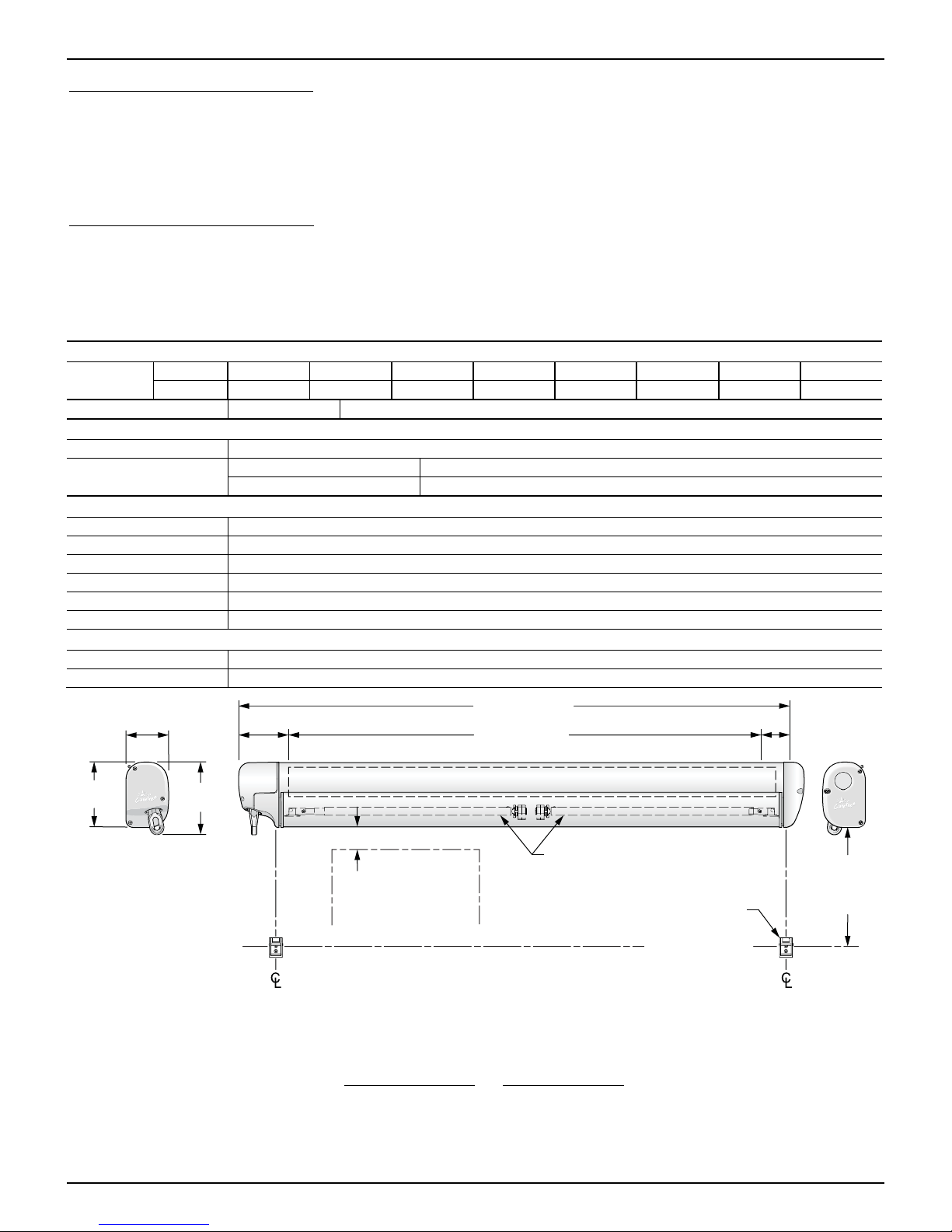
Product Overview.......................................................................................................................... 1
Canopy Replacement - Manual Crank ......................................................................................... 2
Canopy Replacement - Motorized................................................................................................ 4
Replacing the Lead Rail ................................................................................................................ 6
Installing the New Lead Rail. ..................................................................................................................6
Arm Replacement.......................................................................................................................... 7
Replacing the Lead Rail Connector........................................................................................................8
Replacing the Case Connector...............................................................................................................8
Pitch Adjustment – Freedom WM ...........................................................................................................8
Motor Replacement ....................................................................................................................... 9
Remove Old Motor..................................................................................................................................9
Install the New Motor............................................................................................................................10
Adjusting the Motor Limits ....................................................................................................................11
Out Limit Switch ................................................................................................................................11
IN Limit Switch ..................................................................................................................................11
Switch Wiring Freedom WM(motorized only) .......................................................................................12
Replacing the Crank.................................................................................................................... 13
Optional LED Lighting................................................................................................................. 14
Switch Installation.................................................................................................................................14
Replacing the LED Strip .......................................................................................................................15
Harness Replacement ..........................................................................................................................16
Standard Maintenance ................................................................................................................ 17
Fabric Care...........................................................................................................................................17
Mildew ...............................................................................................................................................17
Pooling ..............................................................................................................................................17
Leaking..............................................................................................................................................17
Motor Maintenance...............................................................................................................................17
Support Arm Care.................................................................................................................................17
Arm Noise.............................................................................................................................................18
Manual Override (motorized versions only) ..........................................................................................18
Part Number Listing .................................................................................................................... 19
Serial Number/Part Number Location ...............................................................................................19
Freedom WM Illustrated Parts List .......................................................................................................20
Freedom OtD Illustrated Parts List .......................................................................................................22
Freedom WMNL Illustrated Parts List...................................................................................................23
Optional LED Lighting...........................................................................................................................24

052563-301r5 Printed in USA July, 2016
PROPRIETARY STATEMENT
The Freedom WM Awning is a product of Carefree of Colorado, located in Broomfield, Colorado, USA. The
information contained in or disclosed in this document is considered proprietary to Carefree of Colorado.
Every effort has been made to ensure that the information presented in the document is accurate and
complete. However, Carefree of Colorado assumes no liability for errors or for any damages that result
from the use of this document.
The information contained in this manual pertains to the current configuration of the models listed on the
title page. Earlier model configurations may differ from the information given. Carefree of Colorado
reserves the right to cancel, change, alter or add any parts and assemblies, described in this manual,
without prior notice.
Carefree of Colorado agrees to allow the reproduction of this document for use with Carefree of Colorado
products only. Any other reproduction or translation of this document in whole or part is strictly prohibited
without prior written approval from Carefree of Colorado.
SAFETY INFORMATION
This is the safety alert symbol. It is used to alert individuals to potential
personal injury hazards. Obey all safety messages that follow this sysmbol
to avoid possible personal injury or death.
WARNING Indicates a hazardous situation, which if not avoided, could result in death or
serious bodily injury.
CAUTION Indicates a hazardous situation, which if not avoided, may result in minor or
moderate bodily injury.
NOTICE Indicates a situation that may result in equipment-related damage.
General Safety:
WARNING Shock Hazard. Always disconnect battery or power source before
working on or around the electrical system.
WARNING Always wear appropriate safety equipment (i.e. goggles).
CAUTION Always use appropriate lifting devices and/or helpers when lifting or
holding heavy objects.
NOTICE When using fasteners, do not over tighten. Soft materials such as fiberglass and
aluminum can be "stripped out" and lose the ability to grip and hold.
CALIFORNIA PROPOSITION 65
WARNING This product contains chemicals known to the state of California to cause
cancer or birth defects or other reproductive harm. California’s Proposition 65 requires this
warning to be given to customers in the state of California.
Reference Publications located @ www.carefreeofcolorado.com:'
052563-001 Freedom WM Installation Manual
052563-201 Freedom WM Owner's Manual
052573-001 Freedom Freestyle Installation Manual
052576-201 Freedom Freestyle Owner's Manual
052563-301 Service Manual
Carefree of Colorado 2145 W. 6
th
Avenue Broomfield, CO 80020
aScott Fetzer company 303-469-3324 ♦www.carefreeofcolorado.com


Carefree of Colorado Service Manual FREEDOM WM
052563-301r5 1
PRODUCT OVERVIEW
Freedom Awnings are state of the art lateral arm awnings. When retracted, the housing provides
protection against the elements while the streamlined styling blends in with the coach sidewall. The full
tension canopy fabric allows the awning to be partially or fully extended for best shade coverage.
Each unit is equipped with lateral support arms. No vertical arms interfere with coach sidewalls, custom
graphics or equipment that may be mounted on the sidewalls.
Freedom Awning Specifications:
Fully retractable and self-storing;
Available as manual or motorized;
The sealed awning motor operates on standard 12VDC (range 10VDC to 14VDC);
Case and frame are constructed of high-strength aluminum extrusions, protected with a polyester paint finish;
Stainless steel fasteners and hardware.
SPECIFICATIONS
Widths: centimeters 220 244 257 300 350 400 450 500
inches 87 96 101 118 138 157 177 197
Extension: 200cm (80") 250cm (98")
LEADING EDGE POSITION ACTUATION AND CONTROL
Power: Lateral Arm Spring Minimum Tension Open
Position Control: Motorized: Roll Out/In Controlled by Electrical Motor
Manual: Roll Out/In Controlled by Manual Crank
MOTOR SPECIFICATIONS
Motor Type: Tubular
Power: 12VDC Minimum: 10VDC Output: 30 Watts
Nominal Current: 2.5Amps Max Current: 14Amps (stall @ min voltage)
Power Source: Motor and controls are routed and hardwired into the vehicle’s 12V system
Torque Continuous: 6Nm/4.5 ft-lbs. Tightening: 18Nm/13.2 ft-lbs.
Speed 24 rpm
COLORS AVAILABLE
Case Satin, White or Black
Fabric:
1
Vinyl
wm001
Awning Width
Fabric Width
3.8”
[9.7cm]
5.8”
[14.8cm]
6.5”
[16.5cm]
4.25”
[10.8cm]
2.25”
[5.7cm]
Pivot
30”-38”
(optimum)
50”
(maximum)
Pivot
Support Legs
Stored Inside Lead Rail
Top of Door to
Bottom of Case
Clearance:
3” Minimum
Wall Mount
Bottom Bracket for
Support Legs
1 3/8” x 2 1/8”
Figure 1. General Dimensions.
Special Note: Dimensions are provided in centimeters. Conversion formulas are provided below;
Inches = Centimeters =Millimeters
2.54 25.4
Centimeters = Inches x 2.54 Millimeters = Inches x 25.4

FREEOM WM Service Manual Carefree of Colorado
2 052563-301r5
CANOPY REPLACEMENT -MANUAL CRANK
This procedure requires two people.
1. Open the awning 18"-24".
2. Carefully push the lead rail toward the case so that the arms collapse and
the fabric is slack. While holding the lead rail in this position, firmly tie the
elbows of the spring arms together. Use a minimum 1/2" rope - do not use
bungee cords. When tying the rope, use a non-slip knot such as a square
knot or equivalent.
CAUTION Failure to secure the lead rail as described
will allow the spring arms to unexpectedly extend out possibly
causing personal injury and damage to the awning.
WM023
Outer
End Cap
Fabric Retaining Screw
LH End Plate
LH End Cap
Roller Tube
Retaining Screw
Hem Rolls
Against Roller Tube
Pull and Hold
Polycord While
Placing Screw
DETAIL
B
View of RH (Idler) Plug
DETAIL
A
View of LH (Motor) Bearing
#10 x 2
Screw
Figure 3. Fabric Replacement - Manual Crank.
1. Remove the LH outer end cap.
2. Remove the roller tube retaining screw and washer from the center of the crank assembly.
3. Remove the fabric retaining screw from the left lead rail end plate.
4. Remove the RH lead rail end plate and the RH end cap.
5. Slide the roller tube and fabric out of the case and lead rail.
6. (Detail A) Remove the fabric retaining screws located through the end plug on each end of the roller tube.
7. Unroll the old fabric and slide off the roller tube.
8. Unfold the replacement fabric.
NOTICE While the awning fabric is fairly robust, care must be taken not to snag it while sliding the
new fabric into the roller tube or lead rail.
Tip: Lightly spraying the slots with a dry silicone lubricant will help the fabric slide into the slot without
staining the material.
9. (Detail A & B) Slide the black polycord of the fabric into the fabric slot. Orient the fabric with the hem
on the top (the hem will then roll against the roller tube). Center the fabric in the roller tube.
Marquee012
Spring Arms
Firmly Tie
Elbows Together
Figure 2. Tying the Arms.

Carefree of Colorado Service Manual FREEDOM WM
052563-301r5 3
10. (Detail B) After the fabric is centered, pull and hold the excess polycord to one side of the fabric slot.
Place one (1) #10 x 2 PHSD screw through the fabric slot hole and polycord. The screw must be
positioned to thread into the metal of the roller tube slot and the edge of the polycord. The screw action
will pull the polycord further into the slot hole. DO NOT OVERTIGHTEN,maximum torque 16 in-lbs.
11. After the screw is installed, trim the excess polycord.
12. (Detail B) After tightening the fabric in the slot from one end of the roller tube to the other end, repeat
step 5 and 6 to secure the fabric on the opposite end of the roller tube.
13. Roll the fabric onto the roller tube. Note the direction of the wrap as shown. Allow adequate fabric to extend
past the roller tube to cover the distance to the lead rail..
14. Lift the roller tube and fabric up and slide the fabric polycord into the slot of the lead rail while sliding the
roller tube into the case.
15. At the crank, align the square shaft with the crank assembly. Attach using the roller tube retaining
screw removed previously.
16. Align the roller tube and RH end cap and attach the end cap to the case.
17. Center the fabric in the lead rail. Trim any excess polycord flush with the inside of the lead rail end plates.
18. Attach the RH end plate and the fabric retaining screws (both ends).
NOTE: The top screw secures the fabric in the lead rail. The screw should be positioned to thread into the
metal of the lead rail and the edge of the polycord.

FREEOM WM Service Manual Carefree of Colorado
4 052563-301r5
CANOPY REPLACEMENT -MOTORIZED
This procedure requires two people.
1. Open the awning 18"-24".
2. Disconnect power to the awning.
3. Carefully push the lead rail toward the case so that the arms collapse and
the fabric is slack. While holding the lead rail in this position, firmly tie the
elbows of the spring arms together. Use a minimum 1/2" rope - do not use
bungee cords. When tying the rope, use a non-slip knot such as a square
knot or equivalent.
CAUTION Failure to secure the lead rail as described
will allow the spring arms to unexpectedly extend out possibly
causing personal injury and damage to the awning.
WM024a
Outer
End Cap
Fabric Retaining Screws
12-16 in-lbs.
RH End Plate
RH End Cap
Inner
End Cap
15 in-lbs.
Hem Rolls
Against Roller Tube Pull and Hold
Polycord While
Placing Screw
View of RH (Idler) Plug
#10 x 2
Screw
Figure 5. Fabric Replacement - Motorized.
1. Remove the two (2) screws holding the outer end cap. Set the cap and screws aside.
2. On the motor side, remove the fabric retaining screw. It may be necessary to rotate the roller tube to align the
screw with the access hole in the inner cap.
3. Remove the fabric retaining screw from the left lead rail end plate.
4. Remove the RH lead rail end plate and the RH end cap.
5. Slide the roller tube and fabric out of the case and lead rail.
6. Remove the fabric retaining screw located through the RH end plug.
7. Unroll the old fabric and slide off the roller tube.
8. Unfold the replacement fabric.
NOTICE While the awning fabric is fairly robust, care must be taken not to snag it while sliding the
new fabric into the roller tube or lead rail.
Tip: Lightly spraying the slots with a dry silicone lubricant will help the fabric slide into the slot without
staining the material.
Marquee012
Spring Arms
Firmly Tie
Elbows Together
Figure 4. Tying the Arms.

Carefree of Colorado Service Manual FREEDOM WM
052563-301r5 5
9. Slide the black polycord of the fabric into the fabric slot. Orient the fabric with the hem on the top (the
hem will then roll against the roller tube). Center the fabric in the roller tube.
10. After the fabric is centered, on the RH end plug, pull and hold the excess polycord to one side of the fabric slot.
Place one (1) #10 x 2 PHSD screw through the fabric slot hole and polycord. The screw must be positioned to
thread into the metal of the roller tube slot and the edge of the polycord. The screw action will pull the polycord
further into the slot hole. DO NOT OVERTIGHTEN,maximum torque 16 in-lbs.
11. After the screw is installed, trim the excess polycord.
12. Roll the fabric onto the roller tube. Note the direction of the wrap as shown. The view is of the RH plug. Allow
adequate fabric to extend past the roller tube to cover the distance to the lead rail..
13. Slide the fabric into the lead rail and the roller tube into the case.
14. Align the roller tube with the motor drive and bearing. Press the roller tube into the case.
15. Align the RH end cap with the roller tube and case and attach using the screws and spacer removed
previously. Torque screws 15 in-lbs.
16. On the motor side, align the fabric slot of the roller tube and the access slot through the inner end cap.
17. Attach the fabric retaining screw through the motor bearing and into the roller tube.
18. Open and close the awning to confirm that the fabric rolls and unrolls squarely. Adjust the fabric
position in the lead rail as required.
19. Center the fabric in the lead rail. Trim any excess polycord flush with the inside of the lead rail end plates.
20. Attach the RH end plate and the fabric retaining screws (both ends).
NOTE: The top screw secures the fabric in the lead rail. The screw should be positioned to thread into the
metal of the lead rail and the edge of the polycord.
21. Reattach the outer end cap on the LH side. Torque screws to 15 in-lbs.
22. After installing the canopy, it may be necessary to adjust the motor limits for motorized awnings. Refer
to "Adjusting the Motor Limits" on page 11.

FREEOM WM Service Manual Carefree of Colorado
6 052563-301r5
REPLACING THE LEAD RAIL
This procedure requires a minimum of two people. This can be done while the awning is mounted on the vehicle.
If being done before the awning is mounted, set the awning on a clean hard surface such as the floor of the shop.
3. Open the awning completely. There should be some slack in the fabric. If necessary, adjust the motor limits
so that the motor can extend far enough to create slack in the fabric (refer to page 11).
Remove
End Plate
Remove
End Plate
Remove Vertical Support
From Rail, Mark as RH
Remove Vertical Support
From Rail, Mark as LH
Ramp Arm
Connector RampArm
Connector
Center Ramp
(centered in lead rail)
Measure Locations Measure Locations
View of Back of Lead Rail
(arms and fabric not shown for clarity) WM033
Figure 6. Replacing the Lead Rail.
4. Remove the LH and RH end plates and set aside.
5. Remove the vertical supports from the lead rail. Be sure to mark or note which is LH and which is RH.
6. Carefully measure and record the locations of the ramps and arm connectors.
7. Loosen and slide out the outer ramps.
NOTE: It will be necessary to hold and support the lead rail during the removal and assembly.
8. Loosen the arm connector screw for one arm and slide the arm and connector out of the lead rail.
Allow the arm to extend fully and support the arm with a ladder or scaffolding.
9. Repeat for the second arm.
NOTE: If the unit has a center arm, loosen the screw. The arm connector is moved as the lead rail is
slipped from the canopy.
10. Loosen and slide out the center ramp.
11. Slide the lead rail off the canopy fabric. If the unit has a center arm, slide the arm out of the lead rail
while sliding the lead rail off the fabric.
INSTALLING THE NEW LEAD RAIL.
1. Mark the new lead rail with the dimensions and locations measured previously.
NOTICE While the awning fabric is fairly robust, care must be taken not to snag it while sliding
the new fabric into the roller tube or lead rail.
Tip: Lightly spraying the slots with a dry silicone lubricant will help the fabric slide into the slot without
staining the material.
2. Lift the lead rail up and slide onto the fabric. Center the fabric in the lead rail. If the unit has a center
arm, begin sliding the arm into the lead rail at the same time.
3. Slide the center ramp into the lead rail. Do not tighten at this time.
4. Slide one arm connector into the lead rail.
5. Slide the other arm connector into the lead rail.
6. Align the arm connectors with the measurement marks made previously and tighten the screws.
7. Slide the outer ramps onto the lead rail and align with the measurement marks. Align the center ramp in the
center of the lead rail. Tighten all screws to 25-30 in-lbs.
8. Attach the end plates. The top screws are the fabric retaining screws.
NOTE: The top screw secures the fabric in the lead rail. The screw should be positioned to thread into
the metal of the lead rail and the edge of the polycord.
9. After installing the lead rail, it may be necessary to adjust the motor limits for motorized awnings. Refer
to "Adjusting the Motor Limits" on page 11.

Carefree of Colorado Service Manual FREEDOM WM
052563-301r5 7
ARM REPLACEMENT
CAUTION The spring arm is under tension to open. Use extreme care to firmly hold the
spring arms during assembly and disassembly to avoid any sudden or unexpected movement by
the arm. Serious personal injury and/or property damage could occur.
1. Open the awning to the maximum extension or as wide as possible. Adjust the motor limits (see page
11) to allow the lead rail to over extend and create slack in the fabric. This is to minimize the spring
tension in the arms during this procedure.
2. Disconnect power to the awning.
3. Use a scaffold or ladder to firmly support the lead rail.
4. At the lead rail, firmly hold the spring arm and remove the
clip and pin that secures the arm to the lead rail connector.
Set parts aside to be reused.
5. Allow the arm to extend below the lead rail. Support the end
of the arm.
6. Remove the bolt, washer and shim from the case connector.
NOTE: The securing nut floats inside the knuckle. Use care to not lose the nut.
Set Screw
Shim
Arm Stop
Nut
Pin
Knuckle
Case Connector
Shim
Washer
Bolt
WM037
7. Remove the arm from the awning.
If replacing the rail connector, go to page 8 then return here.
If replacing the case connector, go to page 8 then return here.
8. Remove the knuckle from the arm by removing the set screw, pin and arm stop.
9. Install the knuckle and arm stop on the new arm using the pin and set screw removed previously.
Torque set screw to 15-20 in-lbs.
10. Using two people firmly hold the new arm assembly and remove the shipping ties. Allow the arm to
slowly open to its maximum extension.
CAUTION When the arm is closed, it can open with significant force. Use care when
opening the arm.
Tip: Use a floor or ground cover and place one knuckle and arm half on the ground. Have one person
firmly hold the arm half on the ground while the second person carefully opens the other arm half.
11. Lift the arm assembly into position.
Tip: The securing nut floats in the arm knuckle. Wedge a piece of foam, tape or similar material under
the nut to temporarily hold it in line with the hole in the knuckle. This will aid when starting the bolt.
12. Attach the arm to the case connector using the bolt, washer and shim removed previously. Torque bolt
to 30-35 in-lbs.
13. Slide the arm onto the lead rail connector and secure using the pin and clip removed previously.
14. Remove the supports from the lead rail.
15. After replacing the arm, it will be necessary to adjust the pitch to align the lead rail and case. See page 8.
16. Adjust the motor limits as required. See page 11.
Lead Rail Connector
Pin
Clip
Arm
WM036

FREEOM WM Service Manual Carefree of Colorado
8 052563-301r5
REPLACING THE LEAD RAIL CONNECTOR
1. Remove the arm according to the instructions on page 7.
2. Remove the lead rail end plate.
3. Carefully measure and mark the location of the existing
connector and ramp.
4. Loosen the securing screw and slide the existing connector
from the lead rail.
5. Insert the new connector assembly into the lead rail and position at the marks made previously.
NOTICE Failure to position the connector correctly can cause the arm and lead rail to not close
properly.
6. Tighten the outer securing screw.
7. Attach the lead rail end plate.
8. Return to Replacing the Arm on page 7.
REPLACING THE CASE CONNECTOR
1. Remove the arm according to the instructions on page 7.
2. Carefully measure and mark the location of the existing connector.
3. Loosen the clamping screw then slide the wedge from the housing. Lift
both parts from the case.
4. Remove the knuckle and bolt from the new connector and separate the
new wedge and new housing.
5. Slide the housing into the upper channel of the case and the wedge
into the lower channel of the case.
6. Slide the wedge into the housing and position the housing at the marks
made previously. Tighten the clamping screw to 25-30 in-lbs.
NOTICE Failure to position the connector correctly can cause
the arm and lead rail to not close properly.
7. Return to Replacing the Arm on page 7.
PITCH ADJUSTMENT –FREEDOM WM
The Freedom WM provides minor pitch adjustment for aligning the lead rail with the case. This adjustment
is only for fine-tuning the installation. It is not intended as an operational pitch adjustment.
NOTICE When the pitch of the awning is adjusted, it is
important that the lead rail is parallel to the awning housing.
1. Open the awning to access the adjustment screw located on
the arm case knuckle.
2. Have a second person lift up on the lead rail to relieve the
pressure on the adjustment screw.
3. Using a 5mm allen wrench, turn the adjustment screw clockwise
to raise the lead rail; turn the adjustment screw counterclockwise
to lower the lead rail.
4. Repeat for the other side as necessary.
WM013
Raise
Lower
Pitch Adjustment Screw
A
rm Case Knuckle
Figure 7. Pitch Adjustment.
Remove
End Plate
Ramp
Arm
Connector WM039
Wedge
Housing
Clamping
Screw
WM038
Case Connector
Housing

Carefree of Colorado Service Manual FREEDOM WM
052563-301r5 9
MOTOR REPLACEMENT
1. Disconnect power to the awning.
2. If the awning is extended: Carefully push the lead rail toward the case
so that the arms collapse. While holding the lead rail in this position,
firmly tie the elbows of the spring arms together. Use a minimum 1/2"
rope - do not use bungee cords. When tying the rope, use a non-slip
knot such as a square knot or equivalent.
3. If the awning is closed: Firmly brace the lead rail in the closed
position. A second person can hold the lead rail steady during the
disassembly process.
CAUTION Failure to secure the lead rail as described will allow the spring arms to
extend out suddenly possibly causing personal injury and damage to the awning.
REMOVE OLD MOTOR
Fabric Slot
Retaining Screw
Motor
Inner Endcap
Motor Wire
PlugOuter Endcap
Disconnect
Motor Wires
Motor
Screws
Endcap
Screws
(x3)
Spacer
Inside View
Inner Endcap
Spacer
Cut Wire 2" From
Motor and Remove
From Endcap
WM020a
1. Remove the two (2) screws holding the outer end cap. Set the cap and screws aside.
2. Remove the three (3) screws and spacer holding the inner end cap to the case. Remove the two (2) motor
screws.
CAUTION If the awning is closed when the inner end cap is detached, the spring arms will
try to open. Continue to hold the lead rail closed.
3. Carefully pull the inner end cap away from the case.
4. Cut the motor wire approximately 2" from the motor and remove the wire from the end cap. . Set the end cap
aside.
5. Remove the fabric retaining screw.
6. Pull the motor out of the roller tube and set aside.
CAUTION If the awning is closed when the motor is removed, the spring arms will try to
open. Support the roller tube and allow the awning to open slowly then secure the arms by tying the
elbows together as described previously.
Marquee012
Spring Arms
Firmly Tie
Elbows Together

FREEOM WM Service Manual Carefree of Colorado
10 052563-301r5
INSTALL THE NEW MOTOR
“B”
#10 x 2 Screw
12-16 in-lbs.
M4 x 25mm Screw (x3)
25-30 in-lbs.
WM031
Bearing One-Way Drive
Spacer (x1) Plug
Outer End Cap
Route Motor Wire
Thru Hole in End Cap
Route Wire From Vehicle
Thru Hole in End Cap
Inner End Cap
Motor
Screws
Cut & Splice Wires
Match Colors
1. Check that the one-way drive is installed on the new motor assembly with the "B" pointing toward the motor.
CAUTION The one-way drive must be oriented with the "B" facing the motor. If the
drive is not oriented the awning not to operate and the arms will spring out when released.
2. Align the motor with the inner endcap and attach using the motor screws removed previously.
3. Route the new motor wire through the hole in the end cap.
4. Align the one-way drive with the roller tube and start sliding the new motor into the roller tube.
5. Route the wire from the vehicle through the hole in the end cap.
6. Align the bearing on the motor and slide into the roller tube.
7. Align the screw holes in the inner end cap and attach to the awning case using three (3) M4 x 25
screws and 1 spacer in the front attach hole.
8. Through the access hole in the inner end cap, attach the retaining screw through the bearing and into the
fabric slot. The screw must be positioned to thread into the metal of the roller tube slot and the edge of the
polycord. It may be necessary to rotate the roller tube to align the access hole and fabric slot.
9. Trim the excess wire from the motor and vehicle then splice the motor wires to the vehicle wires. Match
the wires (Blue to Blue and Brown to Brown). Fold and tuck the wires and splices to fit inside the outer
end cap.
10. While holding the lead rail, carefully remove any roller tube supports and arm ties. Allow the lead rail to
extend until the fabric is taut. If the lead rail continues to extend after the fabric is taut, the one way
drive was installed backwards. Retie the arms, remove the motor and orient the one way drive as
shown.
11. To test, restore power then extend and retract the awning.
12. After replacing the motor, it will be necessary to adjust the motor limits (page 11).
13. After testing and adjusting the motor limits, attach the outer end cap.

Carefree of Colorado Service Manual FREEDOM WM
052563-301r5 11
ADJUSTING THE MOTOR LIMITS
Endcap Plug
WM011a
“OUT”
“IN”
4mm Hex
4mm Hex
Increase Run Time
Decrease Run Time
Increase Run Time
Decrease Run Time
Out Limit Switch
The “OUT” limit switch stops the motor when the awning is fully extended
1. Extend the awning out completely.
2. Confirm that the arms are fully extended. The motor should stop and the fabric should be tight. If the
motor continues to run, the fabric will sag; or, if the motor quits before the arms are fully extended, it
will be necessary to adjust the “OUT” limit switch.
3. Using a 4mm Allen wrench turn the “OUT” limit switch. CLOCKWISE increases time the motor runs
during extension, COUNTERCLOCKWISE reduces the time the motor runs.
NOTE: It is best to make the adjustments in increments of a single turn. 3 full turns of the screw
equals approximately 2” of fabric extension.
4. Extend and retract the awning several times to confirm that the adjustment is correct.
5. Repeat steps 3 and 4 as required until the awning extends correctly.
IN Limit Switch
The “IN” limit switch stops the motor when the awning is fully retracted.
NOTICE The in-limit switch must be set to shut off the motor when the awning is closed. The
motor must not continue to run after the awning is closed otherwise damage to the motor will occur
if the motor continues to run after the awning is closed.
1. Retract the awning in completely.
2. Confirm that the arms are fully retracted. The motor must stop when the awning is fully retracted. If the motor
continues to run; or, if the motor quits before the arms are fully retracted, it will be necessary to adjust the “IN”
limit switch.
3. Using a 4mm Allen wrench turn the “IN” limit switch. Clockwise increase time the motor runs during
retraction, counter clockwise reduces the time the motor runs.
NOTE: It is best to make the adjustments in increments of a single turn. 3 full turns of the screw
equals approximately 2” of fabric extension.
4. Extend and retract the awning several times to confirm that the adjustment is correct.
5. Repeat steps 3 and 4 as required until the awning retracts correctly.

FREEOM WM Service Manual Carefree of Colorado
12 052563-301r5
SWITCH WIRING FREEDOM WM(MOTORIZED ONLY)
SK002d
1.25”
[3.2cm]
1.88” [4.8cm]
(ref)
#6 x 3/4 Screw
(2 plcs)
1.88”
[4.8cm]
2.88”
[7.3cm]
(ref)
1.25”
[3.2cm]
Min. Clearance
From Mounting Face to
Rear of Switch Connector
Left Side Orientaion
SK002a
CONNECTOR
WIRE COLOR
SK003b
To Ground
To +12VDC
BROWN Motor Wire
BLUE Motor Wire
RED
BLACK
WHITE
BLUE
SK003a
To Ground
To +12VDC
BROWN Motor Wire
BLUE Motor Wire
RED
BLACK
WHITE
BLUE
RH CONNECTOR ORIENTATION LH CONNECTOR ORIENTATION
RED→+12VDC +12VDC
WHITE→BROWN BLUE
BLUE→BLUE BROWN
BLACK→Ground Ground

Carefree of Colorado Service Manual FREEDOM WM
052563-301r5 13
REPLACING THE CRANK
WM026a
Outer End Cap Inner End Cap
with Crank Assy
Spindle Shaft
1. Remove the 2 screws and outer end cap and set aside.
2. Remove the center screw and washer from the crank assy.
3. Remove the 3 screws and spacer from the inner end cap.
4. Slide the old crank assembly off the spindle shaft.
5. Slide the new crank assembly onto the spindle shaft.
6. Attach the inner end cap and crank assembly with the screws and spacer removed previously.
7. Attach the outer end cap with the screws removed previously.

FREEOM WM Service Manual Carefree of Colorado
14 052563-301r5
OPTIONAL LED LIGHTING
Optional LED lighting may be mounted in the lead rail. The wiring runs along the top of the arm.
For motorized awnings: Route the LED wire harness with the motor cable.
For manual crank awnings: The harness is routed through the end of the case, then through the vehicle
wall.
NOTICE The wire should be secured to the wall of the vehicle where it is exposed on the outside of
the vehicle. Use a quality silicone sealant/adhesive.
NOTICE Do not route the wire over sharp edges or heat sources that can cut or fray the wires or
wire insulation.
Damage that is a result of improper routing may void warranty.
SWITCH INSTALLATION
NOTE: Installers may choose to furnish the control switch. The installation requires that the power line
(+12VDC) be attached to a dedicated 2A circuit breaker or a 2A in-line fuse must be installed between the
switch and power source. For easy access, locate the fuse close to the switch.
1. Determine the location of the switch.
2. At the switch location, cut a 1 1/8" x 1
1/2" hole.
3. Wire the switch as shown below. Wire
terminals at the switch are .187, 18-24
awg female disconnects.
NOTE: Allow adequate slack in the
12VDC power line so that the in-line fuse
(installed in step 4) can be accessed from
behind the switch.
4. Install the in-line fuse:
4.1. Near the switch, cut the red
12VDC power line to the switch.
Do not strip the insulation.
4.2. Insert a wire end into one of the
wire channels until it butts up
against the stop.
4.3. Fold that half of the connector
body over until the element
contacts the wire. Use pliers to
crimp the connector closed.
4.4. Repeat for the second wire end.
4.5. Slide the fuse into the fuse port.
Ensure that is firmly seated.
5. Press the in-line fuse, wires and switch
into the mounting hole. Secure the
switch using two (2) #6 x 1/2" screws.
6. Snap the switch bezel over the switch
frame.
LED002c
Vehicle Wall
Red
+12VDC
GND
Single Pole
Single Throw Switch
18awg Wire
(minimum)
Connector at
Lead Rail
LED Strip in Lead Rail
Red
Black
Wire Routed
in Arm
18-24awg
Female Disconnect (x2)
ON
OFF
1.13"
1.5"
1.88"
2.9"
#6 x 1/2” Screw (x2)
2A In-line Fuse
2A In-line Fuse
(+12VDC Line)

Carefree of Colorado Service Manual FREEDOM WM
052563-301r5 15
REPLACING THE LED STRIP
Previous installations placed the LED strip on the inside of the lead rail. In later installations, the LED strip is
mounted on the outside of the lead rail. Outside installations require the LED slot on the outside of the lead rail.
WM043d
Cut Between Pads
to Adjust Length
LED Slot in Bottom
of Lead Rail
LED Strip
HarnessTie Strap Connector
LED Slot
LED Strip
Harness
Tie Strap
Connector
Attached w/
Double Sided Tape
LED Inside Lead Rail
LED Outside Lead Rail Slot Cover
Wire Channel
Wire Channel
1. Extend the awning out completely.
2. Disconnect power to the awning and the LED strip.
3. Use a non-permanent marker to mark the location of the ends of the LED strip.
4. Inside the lead rail, disconnect the strip connector.
5. LED strip inside the lead rail:
5.1. Remove the lead rail end cap.
6. LED strip outside the lead rail:
6.1. Remove the slot covers from the ends of the strip.
6.2. Pull the lead wires and connector out through the hole in the lead rail.
7. Remove the existing LED strip.
8. Clean the slot to remove any dirt and tape residue.
9. Starting at the reference mark on the harness end, press the new strip into the LED slot.
Tip: For inside mount strips, thread the LED strip behind the connectors before pressing the strip into the slot.
10. At the end of the lead rail, cut the LED strip to match the mark made previously. To trim the LED strip,
always cut between the 4-pad cluster as shown.
11. Route the new LED wires as shown and connect to the harness.
11.1. LED strip inside the lead rail: the connector is fixed to the lead rail with double sided tape.
Replace the tape if necessary.
11.2. LED strip outside the lead rail: The wire and connector goes in the empty slot as shown.
12. LED strip inside the lead rail: Attach the lead rail end plate. Ensure that the wire is in the cavity of the
end plate and the wires are not pinched.
13. LED strip outside the lead rail: Press the slot covers into the LED slot.
14. Restore power and test.

FREEOM WM Service Manual Carefree of Colorado
16 052563-301r5
HARNESS REPLACEMENT
(refer to the figure on the previous page)
1. Extend the awning out completely.
2. Separate the LED connectors at the lead rail. Carefully pull the harness from the wire channel at the
top of the arm.
3. At the awning case:
3.1. Freedom WM: The wire is routed with the motor wire. To access the wire, it will be necessary to
remove the outer end cap from the motor side.
3.2. Clip the harness.
3.3. Clamp the harness going into the vehicle to prevent it from falling in the vehicle wall.
4. Connect the new harness to the LED strip.
5. Route the harness through the wire channel. At the arm joints, arch the cable slightly to avoid binding.
Tip: Use a small tool, such as a flat bladed screwdriver, to gently spread open the channel then insert
the cable into the channel. Do this for the entire length of the channel until the cable is fully inserted.
6. At the vehicle wall:
6.1.Route the new harness through the wall to the switch or dimmer module.
Tip: Tie the new harness to the old harness that was cut previously. Use the old harness to pull the
new harness through the wall to the desired location.
6.2.Seal the wall entrance hole and harness with a quality silicone sealant.
6.3.Connect the new harness to the switch. Two (2) .187, 18-24 awg female disconnects are provided if
connecting to a switch.
6.4.Alternate method: At the wall, splice the new harness to the existing harness using 24 awg butt
connectors. Push the connectors into the vehicle wall. Seal the wall entrance hole and wires with a
quality silicone sealant.
NOTE: Be sure to allow enough harness from the arm to provide a slack in the harness and adequate
length for the connectors to be pushed inside the wall before sealing the hole and harness with a quality
silicone sealant.
Other manuals for Freedom WM
2
Table of contents
Other Carefree Tent manuals

Carefree
Carefree Buena Vista+ User manual

Carefree
Carefree PIONEER LITE User manual

Carefree
Carefree Travel'r Arms and Canopy User manual

Carefree
Carefree RV User manual

Carefree
Carefree ASCENT User manual

Carefree
Carefree Eclipse User manual

Carefree
Carefree SPIRITFX User manual

Carefree
Carefree TRAVEL'R User manual