Carefree RV User manual

070026-020 Printed in USA August, 2018
A
FTERMARKET
I
NSTALLATION
M
ANUAL
ALTITUDE ARMS AND CANOPY
THIS MANUAL PROVIDES INSTRUCTIONS FOR THE BASIC INSTALLATION OF THE AWNING.
RV
Read this manual before installing or using this product. Failure to follow the instructions
and safety precautions in this manual can result in personal injury and/or cause the
product to not operate properly.
T
ABLE OF
C
ONTENTS
Product Overview.......................................................................................................................... 1
Component Checklist..............................................................................................................................2
Required Pre-Installation Preparation ......................................................................................... 3
Upgrades to Existing Awnings................................................................................................................3
Installing an Awning Rail.........................................................................................................................4
Roller Tube Endcaps..............................................................................................................................4
Top Mounting Brackets...........................................................................................................................4
Installation ..................................................................................................................................... 5
Attaching the Roller Tube.......................................................................................................................5
Cable Routing at the Top of the Arm..............................................................................................5
Routing LED Harness to Bottom of the Arm...................................................................................5
Mounting the Awning..............................................................................................................................6
Mounting the Arms .........................................................................................................................6
Securing the Fabric.................................................................................................................................7
Switch and Wiring Installation ..................................................................................................... 8
Wire Routing...........................................................................................................................................8
Carefree Connects Power Cable............................................................................................................8
Awning Control Switch............................................................................................................................9
Optional LED’s............................................................................................................................. 10
Switch Installation for LED's.................................................................................................................10
Optional Wire Covers.................................................................................................................. 11

P
ROPRIETARY
S
TATEMENT
The Altitude Awning is a product of Carefree of Colorado, located in Broomfield, Colorado, USA. The
information contained in or disclosed in this document is considered proprietary to Carefree of Colorado.
Every effort has been made to ensure that the information presented in the document is accurate and
complete. However, Carefree of Colorado assumes no liability for errors or for any damages that result
from the use of this document.
The information contained in this manual pertains to the current configuration of the models listed on the
title page. Earlier model configurations may differ from the information given. Carefree of Colorado
reserves the right to cancel, change, alter or add any parts and assemblies, described in this manual,
without prior notice.
Carefree of Colorado agrees to allow the reproduction of this document for use with Carefree of Colorado
products only. Any other reproduction or translation of this document in whole or part is strictly prohibited
without prior written approval from Carefree of Colorado.
S
AFETY
I
NFORMATION
This is the safety alert symbol. It is used to alert individuals to potential
personal injury hazards. Obey all safety messages that follow this symbol to
avoid possible personal injury or death.
WARNING
Indicates a hazardous situation, which if not avoided, could result in death or
serious bodily injury.
CAUTION
Indicates a hazardous situation, which if not avoided, may result in minor or
moderate bodily injury.
NOTICE
Indicates a situation that may result in equipment-related damage.
General Safety:
WARNING
Shock Hazard. Always disconnect battery or power source before
working on or around the electrical system.
WARNING
Always wear appropriate safety equipment (i.e. goggles).
CALIFORNIA PROPOSITION 65
WARNING
This product contains chemicals known to the state of California to cause
cancer or birth defects or other reproductive harm. California’s Proposition 65 requires this
warning to be given to customers in the state of California.
CAUTION
Always use appropriate lifting devices and/or helpers when lifting or
holding heavy objects.
NOTICE
When using fasteners, do not over tighten. Soft materials such as fiberglass and
aluminum can be "stripped out" and lose the ability to grip and hold.
Carefree of Colorado www.carefreeofcolorado.com a Scott Fetzer company

Carefree of Colorado Aftermarket Installation Manual Altitude
070026-020 1
PRODUCT OVERVIEW
The adjustable pitch Altitude provides motorized awning
comfort with Carefree's standards for looks, strength and
dependability with a successful blend of style, quality and
economy.
The variable pitch offers 6 settings from flat (3˚) to steep (16˚).
The awning roller tube and arms are made from light weight,
no-rust aluminum. The awning fabric is heavy weight vinyl.
White and RGB LED lighting is available with the strip
mounted in the roller tube or at the awning rail.
Specifications:
MAXIMUM EXTENSION: 90 inches MAXIMUM LENGTH: 20 feet
PITCH: FLAT 3˚DROP:approximately 6 inches
STEEP 16˚approximately 26.5 inches
Angle is Canopy vs horizontal Measurement is from centerline of Awning Rail to centerline of roller tube
MOTOR: Power: 10VDC–14VDC Circuit Rating: 15 amp motor mounted in arm
POWER SOURCE: Motor and controls are routed and hardwired into the vehicle’s 12V system
EXTEND ACTUATION: Gas Shock
POSITION CONTROL: Motorized roll out/in
CONTROLLER: Standard: 3 position, momentary
ON, center OFF; DC polarity reversing switch with
dynamic brake.
Optional: BT12 Wireless Awning Control System
COLOR: Frame: White, Black
Canopy: Vinyl with Weatherguard or FLXguard. Refer to sales literature for options.
LED LED strip mounted in roller tube
Power: 1A, 12VDC
Control Single pole, single throw switch (SR0101) Note: The Switch kit is ordered
separately. Kit includes in-line fuse holder and 2A spade type fuse. For an installer
furnished control switch, see note under "Switch Installation".
* Fabric Width is measured at Awning Rail. Tapered canopy will
measure approximately 5" shorter at Roller tube.
Awning Length
Centerline
of Motorized Arm
Centerline
of Idler Arm
6” min.
Clearance
from top of
door
Fabric Width at Awning Rail* 2.5"2.5"
90o
Typ.
2.8" 3.5"
5.75"
58.4" 53.875"
Alt034
Flat Pitch
Steep Pitch
Alt002

ALTITUDE Aftermarket Installation Manual Carefree of Colorado
2 070026-020
COMPONENT CHECKLIST
ITEM DESCRIPTION QTY NOTE
1 Arm Assembly, LH 1 1
2 Arm Assembly, RH 1 1
3 Roller tube Assembly Ordered Separately 1 1
4 Endcap, Roller Tube 2
5 Top Bracket 2
6 Hole Plug 4
7 Screw, Truss Head endcap attach #10 x 5/8 6
8 Screw, Phillips top bracket attach #10 x 2 1/4 2
9 Nut, Nylock top bracket attach #10 2
10 Screw, Lag arm attach #14 x 1 1/2 12
11 Moly Rivet arm attach – alternate 3/16 8
12 Screw, Lag arm attach – top #14 x 2 ½ 4
13 Screw, Hex Washer Head canopy #6 x 3/8 2
14 Switch Kit 1 2
15 Wire Cover, Upper, Optional 1 3
16 Wire Cover, Lower, Optional 1 3
Notes: 1. Awning configuration is specified at time of order, including awning length, fabric, color etc. Check awning
assembly against original purchase order. Arms are configuration specific and are not interchangeable.
2. Installers may choose to furnish the control switch. The switch must be a DC polarity reversing switch
with dynamic brake. Not used with the BT12 Wireless Awning Control System.
3. Wire Covers (15, 16) are optional and must be specified at time of order.
4
14
5
1 2
Alt033
15
16
3
4
6
12111098 137

Carefree of Colorado Aftermarket Installation Manual Altitude
070026-020 3
REQUIRED PRE-INSTALLATION PREPARATION
1. Park the vehicle on a flat surface and level the unit.
2. Check where the awning arms will be installed. The arms fit snug to the side of the vehicle and must not
cover or interfere with exhaust vents, lights etc.
3. If there is an awning rail installed, check that the awning rail runs the full length of the awning. Please
refer to the note under "Installing an Awning Rail" before proceeding.
UPGRADES TO EXISTING AWNINGS
NOTICE If the existing awning canopy has a metal wrap (Uniguard, Alumaguard), it will be
necessary to replace the existing canopy with a new canopy that has FLXguard or vinyl weatherguard.
1. Carefully mark the centerline location of the existing arms.
2. Extend the awning per the awning manufacturer’s instructions.
3. Remove the canopy retaining screws in the awning rail.
4. For motorized awnings, disconnect power to the awning.
Upgrades for a Manual Awning
Manual awnings contain springs in the roller tube. Follow the manufacturer’s service procedures to safely
remove the springs.
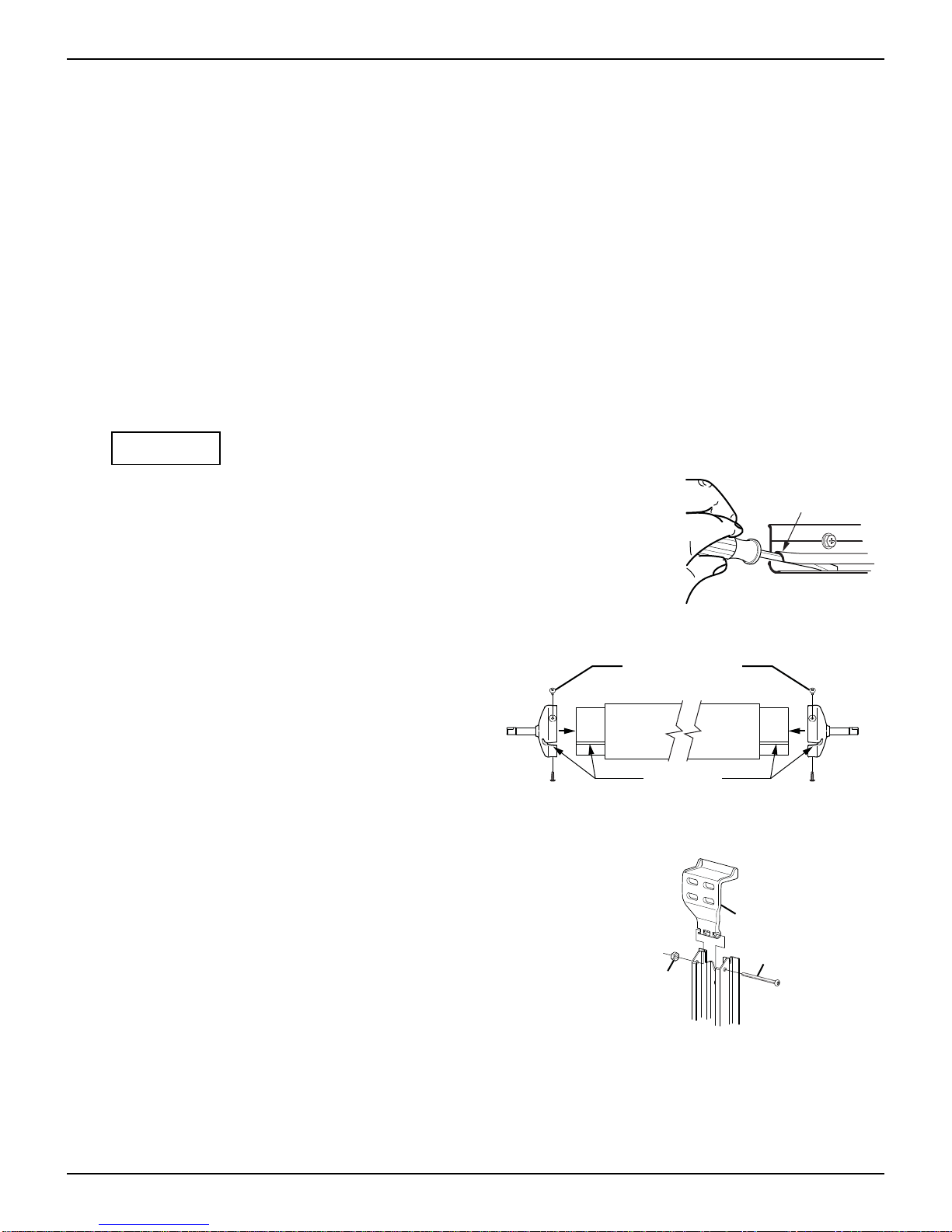
CAUTION This procedure requires working with the roller tube springs. When removed
from the arm, the spring is under extreme tension and will unwind quickly. Keep hands and
clothing clear! Do not try to hold the end plug by hand, use vice grips or similar tools. Failure to
follow the instructions can result in personal injury and property damage.
1. On one arm, remove the end plug, endcap and spring from the arm.
1.1. It will be necessary to hold the arm and move it out of the way when the
end plug is removed.
1.2. It will be necessary to support the roller tube until the other side is
disconnected.
2. Repeat for other side.
3. Allow the roller tube and canopy to hang down the side of the vehicle.
4. Remove the arms from the vehicle.
5. Remove any existing brackets.
6. Remove the springs, end plugs and endcaps from the roller tube.
7. Plug and seal all mounting holes. The mounting holes of the new arms may not match the old awning arms.
Upgrades for a Motorized Awning
1. Determine the existing wiring configuration:
1.1. If the existing installation uses an external wall plug, the installer must furnish the mating plug for
the new motor wires or remove the wall connector and wires. Plug and seal the hole then follow
the standard wiring instructions.
1.2. Configuration A –Motor wires connect directly to a control switch. It is not necessary to remove the
existing switch. The switch must be a DC polarity reversing switch with dynamic brake. If unsure of the
switch type, replace the switch with the included switch.
1.3. Configuration B – Control box electronics (including auto-retract). . Disconnect and remove the
existing control box, wiring and switches. The system is replaced with the single switch control or
the Carefree BT12 Wireless Awning Control System.
2. On one arm, disconnect the roller tube from the arm.
2.1. The arm will extend out when the roller tube is disconnected.
2.2. It will be necessary to support or hold the roller tube until the
other side is disconnected.
SF017a
Unwind
End
Plug
ViceGrips
Travelr014e
Roller Tube Assembly
End CapEnd Cap

ALTITUDE Aftermarket Installation Manual Carefree of Colorado
4 070026-020
3. Repeat for other side.
4. Allow the roller tube and canopy to hang down the side of the vehicle.
5. Remove the arms from the vehicle.
6. Remove any existing brackets.
7. Plug and seal all mounting holes. The mounting holes of the new arms may not match the old awning arms.
INSTALLING AN AWNING RAIL
NOTE: If the vehicle already has a full-length awning rail installed, skip to step 5. The awning rail and arms must
be positioned so that any existing trim does not interfere with the awning arm when in the closed position.
1. Determine the optimum positioning of the awning so that the arms will not interfere with the door frame or
light fixtures. The centerline of the awning rail should be above the door opening a minimum of 6". After
determining mounting position, mark the position with a chalk line.
2. Awning rail must be level.
3. Seal the back of the rail with silicone sealant or putty tape.
4. Align the awning rail onto the wall and secure with #10 x 3/4” screws. Use all the attach holes in the rail.
NOTICE Make sure the screws are securely mounted to the structural frame of the vehicle.
5. Use a screwdriver to spread open one end of the awning rail on the
installation side.
6. File any sharp edges or burrs from the end of the rail. This will help
protect the awning fabric from damage during installation.
7. Spray inside the awning rail track with a dry silicone lubricant.
ROLLER TUBE ENDCAPS
1. Press the endcaps onto the ends of the roller
tube.
1.1. The slots in the endcaps must line up with
the slots in the roller tube
1.2. The cap must be fully inserted onto the
roller tube. The endcap must seat squarely
over the end of the roller tube.
2. Attach each endcap with three (3) #10 x 5/8 truss head screws.
TOP MOUNTING BRACKETS
On each arm attach the top mounting bracket to the channel
using one (1) #10 x 2 ¼ screw and nylock nut.
Spread open
the end of the
awning rail
SF030
Align Slots
#10 x 5/8 Screw
(3 per endcap)
EndcapEndcap
Alt030
Top Mounting Bracket
#10 x 2.25 Screw
#10 Nylock Nut
Alt031

Carefree of Colorado Aftermarket Installation Manual Altitude
070026-020 5
INSTALLATION
ATTACHING THE ROLLER TUBE
FOR AWNING UPGRADES WITH THE CANOPY ALREADY INSTALLED ON THE VEHICLE, start at “Mounting the Arms” on
page 6.
1. On the RH (motor) arm, press the roller tube shaft into the hole in the motor head. It may be necessary
to twist the roller tube to align the flats on the roller tube shaft with the flats in the motor head bearing.
NOTE: The retaining clips are factory installed in the rear head cover as shown.
2. Press the retaining clip in until it is firmly
seated in the groove of the shaft. It may be
necessary to shift the roller tube shaft until the
clip aligns with the groove of the shaft.
NOTICE The roller tube must be fully
inserted into the head for the clip to align
with the groove on the shaft. The roller
tube can disengage if the clip does not
seat in the groove of the shaft.
3. On the LH (idler) arm, press the roller tube
shaft into the hole in the idler head.
4. Press the retaining clip in until it is firmly
seated in the groove of the shaft. It may be
necessary to shift the roller tube shaft until the
clip aligns with the groove of the shaft.
5. On the back of the motor and idler heads,
remove the plastic retaining clip covers.
6. Rotate the access covers up and snap into
the retaining clip openings.
7. Decide on the location of the switches to
determine the cable routing.
Cable Routing at the Top of the Arm
1. Remove the cable tie at the top of the motorized arm. Partially open the arm being careful to not let the
arm extend more than 6”.
CAUTION The arm is under tension from the gas shock located in the arm.
2. Pull the cables from the back of channel and out the pass-thru hole in the top of the channel.
3. Close the arm.
4. Secure the top of the arm in the closed position using a
plastic wrap or equivalent.
Routing LED Harness to Bottom of the Arm
1. On back of the motor arm, carefully pull the Connects
cable from the channel.
2. Route the LED harness through the routing slot on the
side of the arm and down the rear channel.
NOTE: Allow enough slack to create a 3" loop between
the canopy and rail.
3. Press the Connects cable into the channel on top of the
LED harness.
Motor Cable Connects Cable
LED Harness
Route LED Harness
in Channel Press the Cable
into Channel over
the LED Harness
Alt027b
Routing
Slot
Allow Slack for a
3" Loop Between
Canopy and Rail
Back of
Idler Head
Alt035
Retaining Clip Retaining Clip
Groove Groove
Back of
Motor Head
Clip Cover
Access
Cover
Access
Cover
Clip Cover

ALTITUDE Aftermarket Installation Manual Carefree of Colorado
6 070026-020
MOUNTING THE AWNING
NOTICE It is recommended that at least three people install the awning due to its size and weight.
1. On the awning rail, mark the location of the centerline of the idler and motor arm assemblies.
FOR AWNING UPGRADES WITH THE CANOPY ALREADY INSTALLED ON THE VEHICLE, go to step 4 “Mounting the Arms”.
2. Unroll the canopy one wrap.
NOTE: While the awning fabric is fairly robust, care must be taken not to snag it on the awning rail.
3. With one person holding each arm, the third person should thread the polyrod (the plastic rod on the
edge of the fabric) into the awning rail. Carefully move across the vehicle, gently pulling the fabric into
the rail, until the awning is in the desired location.
NOTICE During assembly and installation, the arm assemblies must remain perpendicular to
the roller assembly. Failure to handle the arm assemblies carefully can bend the drive shaft.
Mounting the Arms
4. Position the motor arm on the coach: Align the center of the arm with the centerline marked in step 2.
Butt the top of the rear channel against the awning rail as shown.
5. Hold the arm in position and drive a screw through
the upper access hole and rear channel into the
vehicle wall.
6. Confirm that the arm is perpendicular to the
awning rail then drive a screw through the lower
access hole and rear channel into the vehicle wall.
7. Hold the idler arm assembly perpendicular to the
awning rail and drive a screw through the upper
access hole and rear channel into the vehicle wall.
8. Confirm that the arm is perpendicular to the
awning rail then drive a screw through the lower
access hole and rear channel into the vehicle wall.
9. Hold the awning closed and carefully remove the
cable ties at the top of the arms. The awning will
open a few inches.
10. Open the awning to access the remaining
mounting holes. To open:
10.1. Temporarily connect the ends of the
motor wires to a 12V-14V source (i.e. drill
battery). If the awning does not begin to
move, reverse the leads.
10.2. Remove the battery.
11. Attach each arm through the top brackets using
two (2) each #14 x 2 1/2" lag screws. Requires a
5/32" pilot hole.
12. Attach each arm in the additional positions
(marked with an *) shown (4 places per arm).
Butt Rear Channel
Against Awning Rail
*
NOTE:
If mounting into structure: Use #14 x 1 1/2" lag screws.
Requires a 5/32" pilot hole.
If mounting to the outer skin only: Use 3/16" moly rivets.
Requires a 7/32" (#4) hole. Alt032
#14 x 1 1/2" Lag Screw
(2 per arm)
#14 x 2 1/2"
Lag Screw
(2 per arm)

Carefree of Colorado Aftermarket Installation Manual Altitude
070026-020 7
13. Install the hole plugs in the front channel:
13.1. From the back of the channel, insert the plug into the hole.
13.2. Twist to lock into place.
FOR AWNING UPGRADES WITH THE CANOPY ALREADY INSTALLED ON THE VEHICLE, go to “Attaching the Roller
Tube” on page 5.
SECURING THE FABRIC
1. Roll the awning in and out several times to make sure that the fabric rolls up straight.
2. Attach the canopy in the awning rail using one #6 x 3/8" hex head
screw on one side of the awning. Place screw through awning rail,
fabric and polyrod approximately 1” in from the end of the fabric.
3. On the opposite side, pull the fabric tight in the awning rail place one
#6 x 3/8" hex head screw on one side of the awning. Place screw
through awning rail, fabric and polyrod approximately 1” in from the
end of the fabric.
Fabric
1"
#6 x 3/8
Screw
Polyrod
LG008
Awning Rail
Hole Plug
(2 per arm)
Place Plug
in Hole
Twist to
Lock in Place
View Inside of Arm Channel
Alt005

A
LTITUDE
Aftermarket Installation Manual Carefree of Colorado
8 070026-020
SWITCH AND WIRING INSTALLATION
WARNING
Shock Hazard. Always disconnect battery or power source before
working on or around the electrical system.
Notes: 1. Failure to follow the wiring instructions in this publication may void the motor warranty.
2
. DO NOT wire two or more motors to one switch—No parallel wiring.
3. All wiring must conform to NEC (National Electrical Code) and local codes.
4
. OEM's may choose to furnish the control switch. The switch must be a DC polarity reversing
switch with dynamic brake.
W
IRE
R
OUTING
1. Determine the final location of the switches.
NOTE: There is approximately 8 feet of wire from the wall entry point for upper wire routing, approximately 4
feet of wire from the wall entry point for lower wire routing. Controls should be located within this distance.
1.1. If the distance from point of entry to the switch location is greater than stated above, the installer
must furnish a splice between the cables and switch location.
For motor wires use 14awg wire.
For Connect wires use 16awg wire.
For LED wires use 18awg wire.
2. On the motor side:
2.1 For top routing, drill two (2) 5/16"
holes through the pass through slots
at the top of the arm.
2.2 For bottom routing drill one 7/16" hole
as shown.
3. On the idler side, drill a 5/16" hole through
the vehicle wall to route the Connects
cable into vehicle.
4. Route the cables through the hole to the
switch location.
5. For the LED harness:
5.1 For installations with upper cable
routing, route the LED harness into
the vehicle with the motor cable.
5.2 For lower cable routing, refer to the
wire routing preparation on page 5.
6. Seal the cables and entrance hole(s)
using a quality filler and sealant.
C
AREFREE
C
ONNECTS
P
OWER
C
ABLE
An accessory power cable is installed in the motor and idler arms and routed in the back of the mounting
rail. These are for optional Carefree Connects.
NOTE: If the installer chooses not to connect the cables, they can be trimmed flush at the bottom of the rail.
The cables should be connected
to a single 5A circuit.
Route the cables into the vehicle
and connect to power and
ground as shown.
+12VDC
(recommended 5A Circuit)
GND
Red
Black
Red
Black
Carefree Connects Cable
in Idler Arm
(Connector Located in Arm Elbow
)
Carefree Connects Cable
in Motor Arm
(Connector Located in Arm Elbow
)
Alt015
Connects
Cable
Motor
Cable
5/16" Hole
(x2)
Cable Routing at Top of Arm
Cable Routing at Bottom of Arm Alt008b
LED
Harness
Idler Arm Motor Arm
Motor
Cable
Connects
Cable
LED
Harness
7/16" Hole
Connects
Cable
5/16" Hole
Connects
Cable
5/16" Hole

Carefree of Colorado Aftermarket Installation Manual Altitude
070026-020 9
If installing the BT12 Wireless Awning Control System use the instructions in 070029-001
“BT12 Installation Manual” for the controls wiring and setup.
AWNING CONTROL SWITCH
1. At the switch location, cut a rectangular hole 1.25" [3.2cm] x 1.88" [4.8cm].
2. Determine the switch orientation:
2.1. The wires of the connector extend from the
side of the switch with 3 terminals on the
back.
2.2. For wire routing on the right side of the
switch as shown orient the switch with the 3
terminals on the right.
2.3. For wire routing on the left side of the switch
as shown in Detail C, orient the switch with
the 3 terminals on the left.
2.4. Push the switch into the faceplate until the
tabs on the switch “click” into place behind
the faceplate. Ensure that the switch and
faceplate are oriented so that the lettering is
up and the wires are oriented as desired.
2.5. Set switch aside.
3. Route the awning motor wires through the switch hole and attach to the switch connector:
CONNECTOR
WIRE COLOR LH CONNECTOR ORIENTATION RH CONNECTOR ORIENTATION
RED→+12VDC +12VDC
WHITE→RED (motor wire) BLACK (motor wire)
BLUE→BLACK (motor wire) RED (motor wire)
BLACK→Ground Ground
4. Run a minimum 14 awg wire from the power distribution panel (auxiliary battery circuit) or equivalent.
The circuit should be protected by a 15-amp fuse.
5. Run a minimum 14 awg wire to system ground.
NOTE: If the wire run is 30 feet or longer, use 12awg wire to prevent voltage drop.
6. Route the two wires through the mounting hole. Butt splice the 12VDC wire to the RED connector wire.
Butt splice the ground wire to the BLACK connector wire.
7. Attach the connector to the switch.
8. Restore power and test the switch operation. If the awning operates opposite to the switch plate markings:
Shut off power;
Reverse motor wires connected to the blue and white connector wires;
Restore power and test.
9. Push the wires, connector and switch into the mounting hole and secure the switch plate. Use two (2)
#6 x 3/4" flat head screws.
SK003a
To Ground
To +12VDC
BLACK Motor Wire
RED Motor Wire
RED
BLACK
WHITE
BLUE
SK003d
To Ground
To +12VDC
BLACK Motor Wire
RED Motor Wire
RED
BLACK
WHITE
BLUE
SK002d
1.25"
[3.2cm]
1.88" [4.8cm]
#6 x 3/4 Screw
(2 plcs)
1.88"
[4.8cm]
2.88"
[7.3cm]
(ref)
1.25"
[3.2cm]
Min. Clearance From Mounting
Face to Rear of Connector
Left Side Orientaion

ALTITUDE Aftermarket Installation Manual Carefree of Colorado
10 070026-020
OPTIONAL LED’S
LED options available on the Altitude:
1) White LED strip mounted in the roller tube with the power harness routed through the canopy.
2) White LED strip mounted at the awning rail (strip holder is sewn to the canopy).
SWITCH INSTALLATION FOR LED'S
A single pole switch and 2A fuse is required for the white LED installations and is optional for RGB
installations. For RGB lights, the single pole switch is used as an optional power on/off control allowing the
lights to be shut off if the awning is retracted with the lights on.
NOTES:
a) Installers may choose to furnish the control switch. The installation requires that the power line
(+12VDC) be attached to a dedicated 2A circuit breaker or a 2A in-line fuse must be installed
between the switch and power source. For easy access, locate the fuse close to the switch.
b) Per RVIA Low Voltage Systems in Conversion and Recreation Vehicles Chapter 3, Section 3-1: For
Carefree LED strip lighting near the awning rail: when the 24AWG power harness is spliced or
connected 10" or less from the harness connector using a heavier gauge wire, the fuse size is
determined by the heavier wire gauge.
1. Determine the location of the switch.
2. At the switch location, cut a 1 1/8" x 1 1/2" hole.
3. Wire the switch as shown below. Wire terminals at the switch are .187, 18-24 awg female disconnects.
NOTE: Allow adequate slack in the 12VDC power line so that the in-line fuse (installed in step 4) can be
accessed from behind the switch.
4. Install the in-line fuse:
4.1. Near the switch, cut the red 12VDC power line to the switch. Do not strip the insulation.
4.2. Insert a wire end into one of the wire channels until it butts up against the stop.
4.3. Fold that half of the connector body over until the element contacts the wire. Use pliers to crimp
the connector closed.
4.4. Repeat for the second wire end.
4.5. Slide the fuse into the fuse port. Ensure that is firmly seated.
5. Press the in-line fuse, wires and switch into the mounting hole. Secure the switch using two (2) #6 x
1/2" screws.
6. Snap the switch bezel over the switch frame.
LED020
LED Strip
Vehicle Wall
Red
+12VDC
GND
Switch
18awg Wire
(minimum)
Red
Black
2A In-line Fuse
See Switch Detail
ON
OFF
2A In-line Fuse
(+12VDC Line)
Red
+12VDC
Single Pole, Single Throw Switch
18awg Wire
(minimum)
Red (from power harness)
18-24awg
Female Disconnect (x2)
2A In-line Fuse
GND
Red
+12VDC
Lighted Single Throw Switch
18awg Wire
(minimum)
Red (from power harness)
2A In-line Fuse
18-24awg
Female Disconnect (x2)
1.13"
1.5"
#6 x 1/2" Screw (x2)

Carefree of Colorado Aftermarket Installation Manual Altitude
070026-020 11
OPTIONAL WIRE COVERS
Two optional wire covers are available for the Altitude.
For upper wire routing use the upper wire cover. The cover slides
into the channel from the top and over the wires.
For lower wire routing use the lower wire cover. The cover snaps
onto the bottom of the rear channel. The lower cover is purchased
in sets of two (2). These can be applied to both arms for a
balanced aesthetic appearance.
Slide Upper Wire Cover
into Channel and
Over Wires
Push Lower Cover Over End
of Channel. Pins on Cover
Snap into Holes in Channel
Optional Upper Wire Cover
Optional Lower Wire Cover Alt011b
Other manuals for RV
1
Table of contents
Other Carefree Tent manuals

Carefree
Carefree Travel'r Arms and Canopy User manual

Carefree
Carefree Eclipse User manual

Carefree
Carefree Freedom WM User manual

Carefree
Carefree SPIRITFX User manual

Carefree
Carefree TRAVEL'R User manual

Carefree
Carefree ASCENT User manual

Carefree
Carefree PIONEER LITE User manual

Carefree
Carefree Buena Vista+ User manual