manuals.online logo
Brands
  1. Home
  2. •
  3. Brands
  4. •
  5. Carel
  6. •
  7. Humidifier
  8. •
  9. Carel compactSteam Guide

Carel compactSteam Guide

+050000164 - rel 1.1 - 20 Apr. 2010
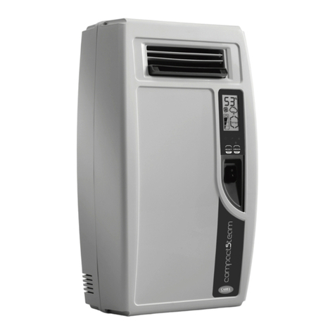
compactSteam
: Cylinder replacement instructions /
Cylinder replacement instructions
The humidier and the cylinder contain live electrical components and
very hot surfaces. All service and maintenance operations must be carried
out by qualied personnel who are aware of the necessary precautions.
Before performing any operations on the cylinder, make sure that the
humidier is disconnected from the power supply. Remove the cylinder
from the humidier only after having drained it completely. Check that
the model number of the new cylinder corresponds with the unit
you are servicing.
Conductivity
Conductivity is a measure of the amount of minerals in the water and the
cylinders are designed to be used with a particular conductivity level. The
cylinder should be matched to the proper conductivity range in the below
table to allow the cylinder to operate to its maximum number of hours.
Steam cylinder reference chart
cylinder conductivity compactSteam
CY0S1A0000 350-1250 µS/cm CH*01*1*** (1.6 kg/h – 3.5 lbs/hr 110 Vac 1-phase)
CY0S1A0000 100-350 µS/cm CH*01*1*** (1.6 kg/h – 3.5 lbs/hr 110 Vac 1-phase)
CY0S1A0000 350-1250 µS/cm CH*02*1*** (2.5 kg/h – 5.5 lbs/hr 110 Vac 1-phase)
CY0S1A0000 100-350 µS/cm CH*02*1*** (2.5 kg/h – 5.5 lbs/hr 110 Vac 1-phase)
CY0S1B0000 350-1250 µS/cm CH*01*2*** (1.6 kg/h – 3.5 lbs/hr 230 Vac 1-phase)
CY0S1C0000 100-350 µS/cm CH*01*2*** (1.6 kg/h – 3.5 lbs/hr 230 Vac 1-phase)
CY0S1B0000 350-1250 µS/cm CH*03*2*** (3.2 kg/h – 7 lbs/hr 230 Vac 1-phase)
CY0S1C0000 100-350 µS/cm CH*03*2*** (3.2 kg/h – 7 lbs/hr 230 Vac 1-phase)
CY0S1C0000 350-1250 µS/cm CH*05*2*** (5.4 kg/h – 12 lbs/hr 230 Vac 1-phase)
CY0S1D0000 100-350 µS/cm CH*05*2*** (5.4 kg/h – 12 lbs/hr 230 Vac1-phase)
Measuring Supply Water Conductivity
Water sample should be taken from the humidier supply connection.
The water sample can be tested on site by available portable cup, or dip
style testers.Tester Manufactures: Hanna instruments, Oakton Instruments,
Myron L. Company, Mettler-Toledo, Denver Instrument Company, and
Electro-Chemical Devices, Inc.
REMOVING AND CLEANING COMPONENTS
WARNING: The cylinder may reach high temperatures. Let it cool down
before touching it or wear protective gloves.
1) To remove the Cylinder
a) Remove the cover
b) Completely drain the cylinder, holding the “drain”button until
the cylinder is empty
c) Turn the humidier o and disconnect the main power supply
2) A: Duct injection units
a) Remove the steam hose from the cylinder
b) Disconnect the wiring from the top of the cylinder
c) Lift up the cylinder support bracket and lift the cylinder out of the
unit, and into a bucket to catch residual water from the cylinder.
2) B: Built-in fan units
a) Unscrew the two bolts on the built-in fan
b) Disconnect the wiring from the top of the cylinder
c) Disconnect the blower from the cylinder and lift the cylinder
out of the unit, and put it into a bucket to catch residual water
from the cylinder.
3) Cleaning the ll, drain tempering valve, drain pump or drain valve,
and drain pan;
a) With power disconnected, turn water supply o and disconnect
water supply hose
b) Remove valves and drain pump/valve by removing screws; check
the condition of inlet lter of the valves
c) Clean with solution of vinegar or diluted acetic acid and a soft brush
d) Rinse parts with fresh water
e) Replace any components that show excessive wear or could not
be completely cleaned. Ensure that the washer and spring are
properly reassembled in the drain valves.
L’umidicatore e il cilindro contengono componenti elettrici sotto tensione
e superci molto calde. Le operazioni di assistenza e manutenzione devono
essere eseguite solamente da personale qualicato, che sia a conoscenza
delle precauzioni necessarie. Prima di eettuare qualsiasi operazione sul
cilindro, assicurarsi che l’umidicatore sia scollegato dall’alimentazione
elettrica. Rimuovere il cilindro dall’umidicatore solo dopo averlo svuotato
completamente dell’acqua contenuta. Vericare che il numero del
modello del nuovo cilindro corrisponda all’apparecchio sul quale si
sta eseguendo il servizio di assistenza.
Conducibilità
La conducibilità è una misura della quantità di minerali nell’acqua e i cilindri
sono stati progettati per essere usati con un livello particolare di conducibilità.
Perché possa funzionare per il numero massimo di ore possibile, il cilindro
deve essere abbinato all’intervallo di conducibilità adeguato riportato in tab.
Tabella di riferimento cilindri vapore
cilindro conducibilità compactSteam
CY0S1A0000 350-1250 µS/cm CH*01*1*** (1.6 kg/h – 3.5 lbs/hr 110 Vac 1-fase
CY0S1A0000 100-350 µS/cm CH*01*1*** (1.6 kg/h – 3.5 lbs/hr 110 Vac 1-fase)
CY0S1A0000 350-1250 µS/cm CH*02*1*** (2.5 kg/h – 5.5 lbs/hr 110 Vac 1-fase)
CY0S1A0000 100-350 µS/cm CH*02*1*** (2.5 kg/h – 5.5 lbs/hr 110 Vac 1-fase)
CY0S1B0000 350-1250 µS/cm CH*01*2*** (1.6 kg/h – 3.5 lbs/hr 230 Vac 1-fase)
CY0S1C0000 100-350 µS/cm CH*01*2*** (1.6 kg/h – 3.5 lbs/hr 230 Vac 1-fase)
CY0S1B0000 350-1250 µS/cm CH*03*2*** (3.2 kg/h – 7 lbs/hr 230 Vac 1-fase)
CY0S1C0000 100-350 µS/cm CH*03*2*** (3.2 kg/h – 7 lbs/hr 230 Vac 1-fase)
CY0S1C0000 350-1250 µS/cm CH*05*2*** (5.4 kg/h – 12 lbs/hr 230 Vac 1-phase)
CY0S1D0000 100-350 µS/cm CH*05*2*** (5.4 kg/h – 12 lbs/hr 230 Vac1-phase)
Misurazione della conducibilità dell’acqua di
alimentazione
Prendere dei campioni di acqua di alimentazione dell’umidicatore per
poterli testare in loco tramite un tester portatile. Produttori dei tester: Hanna
Instruments, Oakton Instruments, Myron L. Company, Mettler-Toledo,
Denver Instrument Company ed Electro-Chemical Devices, Inc.
RIMOZIONE E PULIZIA DEI COMPONENTI
AVVERTENZA: il cilindro potrebbe essere caldo.
Lasciarlo rareddare prima di toccarlo od utilizzare guanti protettivi.
1) Per rimuovere il cilindro
a) Togliere il frontale dell’unità
b) Eliminare completamente l’acqua contenuta all’interno del cilindro
tenendo premuto l’apposito pulsante (‘drain’) nché il cilindro non
è vuoto
c) Spegnere l’umidicatore e scollegarlo dall’alimentazione elettrica.
2) A: Unità per condotta:
a) Rimuovere il tubo del vapore dal cilindro
b) Scollegare i cavi nella parte superiore del cilindro
c) Sollevare la staa di supporto del cilindro, estrarre quest’ultimo
dall’apparecchio e deporlo in un secchio per raccogliere l’acqua
residua contenuta al suo interno.
2) B: Unità con ventilatore a bordo
a) Svitare i due bulloni sul ventilatore
b) Scollegare i cavi nella parte superiore del cilindro
c) Scollegare il ventilatore dal cilindro ed estrarre quest’ultimo
dall’apparecchio sollevandolo e deponendolo in un secchio per
raccogliere l’acqua residua contenuta al suo interno.
3) Pulizia della valvola di alimentazione, miscelazione, la pompa di
drenaggio o la valvola di drenaggio
a) Con l’alimentazione elettrica scollegata, chiudere l’alimentazione
dell’acqua e scollegare il relativo tubo
b) Rimuovere le valvole e la pompa/valvola di drenaggio togliendo le
apposite viti; vericare la condizione del ltro di ingresso delle valvole
c) Pulire con una soluzione di aceto o acido acetico diluito utilizzando
un pennello a setole morbide
d) Sciacquare le parti con acqua fresca
e) Sostituire eventuali componenti che mostrano segni di eccessiva
usura o che non possono essere puliti completamente. Assicurarsi
che la guarnizione sia montata adeguatamente nelle valvole di
drenaggio.
CAREL INDUSTRIES HQs
Via dell’Industria, 11 - 35020 Brugine - Padova (Italy)
Tel. (+39) 049.9716611 - Fax (+39) 049.9716600 e-mail: [email protected] - www.carel.com +050000164 - rel 1.1 - 20 Apr. 2010
REASSEMBLYING AND RESTARTING
The following operations shall be performed with a COLD cylinder.
1) Replace any components that were removed for servicing.
2) To install the Cylinder:
a) Install the new cylinder in the humidier, performing the same
operations in the reverse order.
b) Connect wire ring connectors to cylinder electrodes.
See WARNING label.
c) Replace the blower, and/or the steam hose to the cylinder.
Warning: ensure that the components, hoses and cylinder are
replaced with correct O-rings, and gaskets. Open water supply
and check for leaks. Ensure that the steam hose clamp is snug,
but not over-tightened.
d) Reconnect the power supply.
3) Start with the new cylinder:
a) Switch the unit o. While pressing and holding both the
“reset” and “drain” buttons, switch the unit on.
When the wrench blinks release the two buttons.
b) Press and hold “reset” until the display shows 04.
Warning: DO NOT conrm any value higher than 04. If 05 or
higher is displayed, press “reset” until the display goes back to
the normal operating mode and restart from step a).
c) Press “drain”(minimum 1 second). The cleaning cycle starts. During
the cylinder cleaning cycle, the electrodes are powered and the
cylinder is lled with water until one of the following conditions
occurs:
 •thelevelofthewaterreachesthemaximumlevelsensor;
 •thephasecurrentisequalto20A.
The cylinder will empty. Carel recommends two cleaning cycles.
Go back and repeat from step a). After the second cleaning cycle
has ended, the humidier will start normally.
4) Resetting the cylinder hour counter:
a) Switch unit o. While pressing and holding both the“reset” and
“drain” buttons, switch the unit on. When the wrench blinks
release the two buttons.
b) Press and hold “reset” until the display shows 03
c) Press “drain”(minimum 1 second) to conrm.
The hour counter will be reset once the unit goes back to
normal operation.
5) Final Check:
a) Turn unit o and disconnect power supply.
b) Recheck for water leaks, and replace unit cover.
c) Reconnect power and turn unit on.
RIASSEMBLAGGIO E RIAVVIO
Le seguenti operazioni devono essere eseguite con il cilindro a temperatura
ambiente.
1) Sostituire eventuali componenti diettosi
2) Per installare il cilindro:
a) Installare il nuovo cilindro nell’umidicatore, eseguendo a ritroso le
stesse operazioni eettuate precedentemente.
b) Collegare i cavi di potenza agli elettrodi dei cilindri.
Vedere etichetta di AVVERTENZA.
c) Ricollegare il ventilatore e/o il tubo del vapore al cilindro.
Avvertenza: assicurarsi che i componenti, i tubi ed il cilindro
siano riposizionati con gli O-ring e le guarnizioni corrette.
Aprire l’alimentazione dell’acqua e vericare che non vi siano
perdite. Accertarsi che la fascetta stringi tubo del vapore sia stretto
ma non eccessivamente serrato.
d) Ricollegare l’alimentazione elettrica
3) Avvio con il nuovo cilindro:
a) Spegnere l’apparecchio. Mentre si tengono premuti i due pulsanti
‘reset’ e ‘drain’, accendere l’apparecchio.
Quando il simbolo della chiave inglese lampeggia,
lasciare i due pulsanti.
b) Tenere premuto il pulsante‘reset’ nché sul display non
compare la cifra 04.
Avvertenza: NON confermare nessun valore superiore a 04. Se viene
visualizzata una cifra pari o superiore a 05, premere il tasto‘reset’
nché il display non torna alla normale modalità operativo, e
ripartire dal punto a).
c) Premere il tasto ‘drain’(minimo 1 secondo). Il ciclo di pulizia si
avvia. In questa fase gli elettrodi vengono alimentati e il cilindro
si riempie di acqua nché non si verica una delle seguenti
condizioni:
 •illivellodell’acquaraggiungeilsensorediriempimentomassimo;
 •lacorrentedifaseèparia20A.
Il cilindro si svuota. Carel consiglia due cicli di pulizia.
Tornare indietro e riprendere dal punto a). Una volta terminato il
secondo ciclo di pulizia, l’umidicatore si riavvia normalmente.
4) Azzeramento del contatore orario del cilindro:
a) Spegnere l’apparecchio. Mentre si tengono premuti i pulsanti ‘reset’
e ‘drain’, accendere l’apparecchio. Quando il simbolo della chiave
inglese lampeggia, lasciare i due pulsanti.
b) Tenere premuto il tasto ‘reset’ nché il display non mostra
la cifra 03
c) Premere il tasto‘drain’ (minimo 1s) per confermare.
Il contatore orario verrà azzerato una volta che l’apparecchio tornerà
a funzionare normalmente.
5) Controllo nale:
a) Spegnere l’apparecchio e scollegare l’alimentazione elettrica..
b) Vericare nuovamente che non ci siano perdite d’acqua e
riposizionare il coperchio dell’apparecchio.
c) Ricollegare l’alimentazione elettrica e riaccendere l’apparecchio.
WARNING: RISK OF BURNING/FIRE HAZARD!
Firmly tighten the cable (22-29 in- lbs / 2.5-3.3 Nm)
using the nut and washer supplied.
See diagram below for proper installation.

Other manuals for compactSteam

6

Other Carel Humidifier manuals

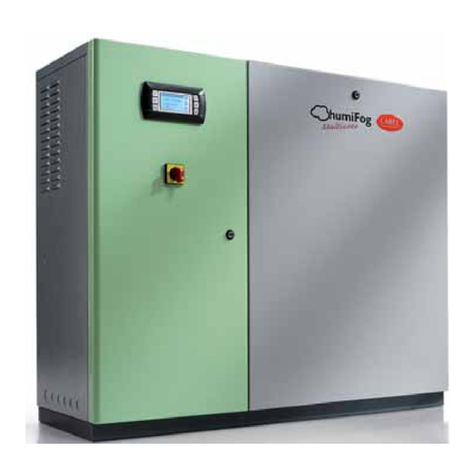
Carel humiFog direct User manual

Carel

Carel humiFog direct User manual

Carel humiSteam Basic User manual

Carel

Carel humiSteam Basic User manual

Carel UE001-065 humisteam User manual

Carel

Carel UE001-065 humisteam User manual

Carel humiSonic User manual

Carel

Carel humiSonic User manual

Carel humiSteam x-plus User manual

Carel

Carel humiSteam x-plus User manual

Carel humiSonic UU04 User manual

Carel

Carel humiSonic UU04 User manual

Carel ultimateSAM Series Guide

Carel

Carel ultimateSAM Series Guide

Carel humiSonic Compact User manual

Carel

Carel humiSonic Compact User manual

Carel KUE OEM User manual

Carel

Carel KUE OEM User manual

Carel humiSonic Compact User manual

Carel

Carel humiSonic Compact User manual

Carel GASTEAM User manual

Carel

Carel GASTEAM User manual

Carel humiFog direct User manual

Carel

Carel humiFog direct User manual

Carel gaSteam-UG User manual

Carel

Carel gaSteam-UG User manual

Carel humiSteam Basic User manual

Carel

Carel humiSteam Basic User manual

Carel humiSonic UU01F User manual

Carel

Carel humiSonic UU01F User manual

Carel heaterStream-UR User manual

Carel

Carel heaterStream-UR User manual

Carel heaterSteam User manual

Carel

Carel heaterSteam User manual

Carel gaSteam 45 User manual

Carel

Carel gaSteam 45 User manual

Carel ultimateSAM User manual

Carel

Carel ultimateSAM User manual

Carel compactSteam CH002V1000 User manual

Carel

Carel compactSteam CH002V1000 User manual

Carel compactSteam User manual

Carel

Carel compactSteam User manual

Carel humiSonic User manual

Carel

Carel humiSonic User manual

Carel compactSteam User manual

Carel

Carel compactSteam User manual

Carel humiFog Multizone User manual

Carel

Carel humiFog Multizone User manual

Popular Humidifier manuals by other brands

Aprilaire 550 owner's manual

Aprilaire

Aprilaire 550 owner's manual

Aroma Sai AHU-4002 instruction manual

Aroma

Aroma Sai AHU-4002 instruction manual

Condair RM Series installation manual

Condair

Condair RM Series installation manual

Hunter 31206 owner's guide

Hunter

Hunter 31206 owner's guide

Crane EE-864 instruction manual

Crane

Crane EE-864 instruction manual

weewell WHC730 user manual

weewell

weewell WHC730 user manual

HoMedics UHE-CM15 quick start guide

HoMedics

HoMedics UHE-CM15 quick start guide

Bionaire BCM6100 Instruction leaflet

Bionaire

Bionaire BCM6100 Instruction leaflet

Boneco W2055A Instructions for use

Boneco

Boneco W2055A Instructions for use

DriSteem VAPORFAN Installation instructions & maintenance operations manual

DriSteem

DriSteem VAPORFAN Installation instructions & maintenance operations manual

Ravanson UH-7015 manual

Ravanson

Ravanson UH-7015 manual

Honeywell Enviracaire Elite HE365A manual

Honeywell

Honeywell Enviracaire Elite HE365A manual

miniland humitop connect Instruction manual, quick guide, and warranty

miniland

miniland humitop connect Instruction manual, quick guide, and warranty

Honeywell HWC775 Series owner's manual

Honeywell

Honeywell HWC775 Series owner's manual

Pro Breeze PB-07-UK/EU instruction manual

Pro Breeze

Pro Breeze PB-07-UK/EU instruction manual

Aprilaire 448 owner's manual

Aprilaire

Aprilaire 448 owner's manual

weewell WHC660 user manual

weewell

weewell WHC660 user manual

Everlasting Comfort S-HUM manual

Everlasting Comfort

Everlasting Comfort S-HUM manual

manuals.online logo
manuals.online logoBrands
  • About & Mission
  • Contact us
  • Privacy Policy
  • Terms and Conditions

Copyright 2025 Manuals.Online. All Rights Reserved.