manuals.online logo
Brands
  1. Home
  2. •
  3. Brands
  4. •
  5. Carel
  6. •
  7. Measuring Instrument
  8. •
  9. Carel AS Series User manual

Carel AS Series User manual

Thank you for your choice. We trust you will be satisfied with your purchase.
General characteristics
CAREL electronic air quality probes, in the versions for duct and environment, have been designed for use in Heating,
Refrigeration and Air-Conditioning sectors. The main applications are in ventilation and air handling systems in homes and
commercial areas.
On the basis of a mixed gas sensor VOC (Volatile Organic Compounds) and a photo-acoustic selective sensor, the air
quality probes allow the qualitative analysis of the air in offices, hotels, meeting rooms, houses, shops, restaurants, etc.
and the quantitative analysis of the contamination caused by polluting gases.
Detected gases
The main gases detected are, for what concerns the volatile organic compounds, a mixture of the following gases: carbon
monoxide CO, sulphur water H2S, solvent vapours, alkane vapours, cigarette smoke, car exhaust, air produced by human
breathing, combustion smoke from wood, paper and plastics. Moreover, the probe detects the concentration of CO2from
350 up to 2000 ppm.
Duct probes (ASD*)
These are used in ducted heating and air-conditioning systems to detect the air quality and the CO 2level present in the
air (only models ASDQ300000 e ASWQ300000).
Code Output description Range Signals
ASDQ100000 VOC 0 to 100% 0 to 10 V o 0 to 20 mA o 4 to 20 mA
ASDQ300000 VOC + CO20 to 100% e 350 to 2000 ppm 0 to 10 V
Environment probes (ASW*)
They are used in heating and air-conditioning systems, installed on the wall in the room, to measure the air quality and the
level of CO2in the air (models ASDQ300000 and ASWQ300000 only).
Code Output description Range Signals
ASWQ100000 VOC 0 to 100% 0 to 10 V o 0 to 20 mA o 4 to 20 mA
ASWQ300000 VOC + CO20 to 100% e 350 to 2000 ppm 0 to 10 V
Installation
Connection
Fig. 2 shows the connection wiring diagrams to the terminal, as well as the pin-strip position for the possible configuration
of the output signal under voltage (default) or current.
Warnings
• The device is calibrated for use in rooms with a stable mixture. The zero and the range of measurement are set by the
manufacturer, using synthetic air with a pre-established quantity of hydrogen. This device is used to measure the
changes in air quality in reference to the zero point established. In some cases, there may be a sudden increase, due to
high loads (new carpets, fresh paint…).
• The average lifetime of the VOC sensor, in the working environments indicated, is 36 months.
• The CO2sensor works correctly if in contact with clean area (400 ppm) for at least 10 minutes, during which time the
auto-calibration procedure is performed.
• The air quality sensor cannot be used for safety applications!
• It is recommended to use shielded cables for the connections, keeping the signal cables separate from the 230/380 V
power cables and the various loads (e.g. contactors), so as to avoid interference and/or faults
• The probes can be integrated in Class I or II appliances, considering the following warnings:
Class I: the G0 power ground must be earthed;
Class II: power to the probe and the control to which it is connected must have double or reinforced insulation.
If the above is not possible, it is necessary, under normal use, to impede user access to the zone where the sensors are
installed.
Wiring
All wiring operations should be performed using multi-pole shielded cables, with 3 or 5 leads, according to the model.
The maximum cable cross-section accepted by the terminals is 1.5 mm2.
0 to 1 Vdc signal: in case of single probes, the voltage output 0 to 10 Vdc can be enabled.
To avoid errors in measurement due to the current from the power supply, a supplementary power supply with external
transformer may be used (e.g.: CAREL code TRA12VDE00 or TRA2400001), and should be connected as described in Fig. 7.
Warning: the transformer must not be earthed, and can be installed in the control’s electrical panel.
The connection cable used should be a 4- or 5-lead multi-pole cable. In this situation, power will not flow to the M-AVSS
connection. In installations with more than one probe, each probe must be powered by its own transformer.
With this configuration, the maximum distance for remote installation is 100 m for the models with one signal (see Fig. 7).
4 to 20 mA signal: for distances greater than 30 m, current outputs should be selected where the systems allows,
properly configuring the jumpers as shown in Fig. 2.
The maximum remote-control distance for current outputs is 200 m.
In case of alternating current power supply the cables used must have a 1.5 mm2cross-section, to reduce noise due to
the current from the power supply.
This noise may cause, in some cases, unstable measurements that can be prevented by using a direct current power
supply or a supplementary power supply, as described in Fig. 7.
Vi ringraziamo della scelta fatta, sicuri che sarete soddisfatti del vostro acquisto.
Caratteristiche generali
Le sonde elettroniche CAREL di qualità dell’aria, sono state sviluppate per essere applicate nei settori del riscaldamento,
della refrigerazione e del condizionamento. Le principali applicazioni sono nei sistemi di ventilazione e trattamento d’aria
in aree domestiche e commerciali.
Utilizzando un sensore a gas misto VOC (Volatile Organic Compounds) ed un sensore fotoacustico selettivo, le sonde di
qualità dell’aria permettono l’analisi qualitativa dell’aria in uffici, hotel, sale riunioni, abitazioni, negozi, ristoranti, ecc. e
l’analisi quantitativa della contaminazione da parte di gas inquinanti.
Gas rilevati
I principali gas rilevati, per quanto riguarda i componenti organici volatili in una miscela di gas, sono: monossido di
carbonio CO, acqua solfurea H2S, vapori di solventi, vapori di alcanoli, fumo di sigaretta, gas di scarico delle automobili,
aria prodotta dal respiro umano, fumo di combustione di legno, carta e materie plastiche.
Il modello combinato misura anche la concentrazione di CO2con un range da 350 fino a 2000 ppm.
Sonde da condotta (ASD*)
Vengono utilizzate negli impianti di riscaldamento e condizionamento che fanno uso di condotte, per rilevare la qualità
dell’aria e il livello di CO2presente nell’aria (solo modelli ASDQ300000 e ASWQ300000).
Codice Descrizione Uscite Range Segnali
ASDQ100000 VOC 0...100% 0...10 V o 0...20 mA o 4...20 mA
ASDQ300000 VOC + CO20...100% e 350...2000 ppm 0...10 V
Sonde da Ambiente (ASW*)
Vengono utilizzate negli impianti di riscaldamento e condizionamento con installazione a muro in ambiente, per rilevare la
qualità dell’aria e il livello di CO2presente nell’aria (solo modelli ASDQ300000 e ASWQ300000).
Codice Descrizione Uscite Range Segnali
ASWQ100000 VOC 0...100% 0...10 V o 0...20 mA o 4...20 mA
ASWQ300000 VOC + CO20...100% e 350...2000 ppm 0...10 V
Installazione
Collegamenti
Nella Fig. 2 vengono riportati gli schemi delle connessioni alla morsettiera e la posizione dei pin-strip per l’eventuale
configurazione del segnale di uscita in tensione (default) o in corrente.
Avvertenze
• Il dispositivo è calibrato per l’utilizzo in ambienti con miscela stabile. Lo zero e il range di misura vengono stabiliti dal
costruttore utilizzando aria sintetica e una quantità prestabilita di idrogeno. Questo dispositivo viene utilizzato per
rilevare i cambiamenti della qualità dell’aria rispetto al punto zero stabilito. In alcuni casi, si può verificare un aumento
improvviso, a causa di un carico elevato del dispositivo (tappeti nuovi, tintura fresca…).
• Il tempo di vita medio per il sensore di VOC, applicato negli ambienti di lavoro indicati, è di 36 mesi.
• Il sensore di CO2lavora correttamente se investito da aria pulita (400 ppm) per almeno 10 minuti, durante i quali viene
effettuata una procedura di autocalibrazione.
• Il sensore di qualità dell’aria non può essere utilizzato per applicazioni ai fini della sicurezza!
• Per i collegamenti si consiglia di usare cavi schermati, separando i cavi di segnale dai cavi di tensione 230/380 V e dai
carichi vari (es. Teleruttori), per evitare interferenze e/o guasti
• Le sonde sono integrabili in apparecchiature di Classe I o II, con le seguenti avvertenze:
Classe I: il riferimento G0 di alimentazione deve essere collegato a terra;
Classe II: si deve prevedere un doppio isolamento o un isolamento rinforzato per l’alimentazione della sonda e del
controllo a cui è collegato. Nel caso ciò non sia possibile, è necessario, nell’utilizzo normale, rendere inaccessibile
all’utilizzatore la zona sensori.
Cablaggio
Per effettuare il cablaggio si consiglia un cavo multipolare schermato da 3 a 5 fili, in funzione dei modelli, con sezione
massima di 1,5 mm2.
Segnale 0...10 Vdc: nel caso delle sonde singole, è possibile abilitare l’uscita in tensione 0...10 Vdc.
Per evitare gli errori di misura dovuti alla corrente di alimentazione si può utilizzare un’alimentazione supplementare da un
trasformatore esterno (ad es.: cod. CAREL TRA12VDE00 o TRA2400001), da collegarsi come riportato in Fig. 7.
Avvertenza: il trasformatore non deve essere collegato a terra e può essere posizionato nel quadro del regolatore.
Il cavo di collegamento sarà un multipolare da 4 o 5 fili. In tale situazione non scorre corrente di alimentazione sulla
connessione M - AVSS. In installazioni con più sonde, ognuna deve essere alimentata dal proprio trasformatore.
Con tale configurazione la distanza massima di remotazione è di 100 m per i modelli a singolo segnale (vedi Fig. 7).
Segnale 4...20 mA: per distanze maggiori di 30 m si consiglia di selezionare, qualora il sistema lo permetta, l’uscita in
corrente, configurando opportunamente i ponticelli come descritto in Fig. 2.
La distanza massima di remotazione per l’uscita in corrente è di 200 m.
Nel caso di alimentazione in alternata è indispensabile utilizzare cavi aventi sezione di 1,5 mm2per ridurre il rumore
dovuto alla corrente di alimentazione.
Tale rumore può provocare, in qualche caso, instabilità di misura che può essere eliminata con alimentazione in continua
o con un’alimentazione supplementare, come riportato in Fig. 7.
cod. +050000630 - rel. 3.2 - 14.03.2007
AS*Q*00000:
sonde da condotta (ASD*) e da ambiente (ASW*) /
duct (ASD*) and environment (ASW*) probes
4 3 2 1
LG GND UB GND
U I
current (mA)
voltage (V)
default
manual
button
manual calibration
LED - calibration
cali brat ion
air qu ality
4.. .20mA
0.. .20mA
U I
curr ent
output 0/4
setting output
current (mA)
voltage (V)
default
manual
button
manual calibration
LED - calibration
cali bratio n
air qu ality
4.. .20mA
0.. .20mA
U I
U I
current
outpu t 0/4
setting output
J1
J2
J3
setting
output
J3
J1
J2
auto
GND UB GND LG
Power
supply
AC DC
10VGND
2 24V~ 15...36V DC
output
3 GND / 0V GND
4 (LQ) 0 10V 0...10V
ground (1) and (3) are electrically
connected on the PCB.
ASDQ100000
ASWQ100000
LQ
LQC
O2 UBGN
D
43 21
CO2
calibration
carbon dioxide CO2
LED - calibration
manual
button manual
calibration CO2
manual
button manual
alibration air quality
LED - calibration
calibrtion
air qualityLQ
power
supply
AC DC
1 0V GND
2 24V~ 15...36V DC
output
3 (CO2)0…10V0
...10V
4 (LQ) 0…10V 0…10V
manual manual
button manual
calibration CO2
button manual
alibration airquality
LED - calibrat ionLED- calibr at ion
calibration
carbon dioxideC
O2
CO2 LQ calibrtion
air qualityLQ
LQ CO2 UB GND
4321
ASWQ300000
ASDQ300000
Dimensioni (mm) /
Dimension (mm)
Collegamenti elettrici /
Elettrical wiring
Fig. 1
Fig. 2
Ø16
84
64
242
36
58
ASDQ100000
CAREL S.p.A.
Via dell’Industria, 11 - 35020 Brugine - Padova (Italy)
Tel. (+39) 0499716611 – Fax (+39) 0499716600
http://www.carel.com – e-mail: [email protected]
CAREL si riserva la possibilità di apportare modifiche o cambiamenti ai propri prodotti senza alcun preavviso.
CAREL reserves the right to modify the features of its products without prior notice.
cod. +050000630 - rel. 3.2 - 14.03.2007
Caratteristiche tecniche
Alimentazione 15...36 Vcc; 24 Vca +/- 10%; 50-60 Hz
Alimentazione gas al sensore* diffusione
Assorbimento (uscite attive) • ASDQ100000: max. circa 120 mA
• ASDQ300000: max. circa 130 mA
Condizioni di immagazzinamento -20T60°C; 95% U.R. non condensante
Condizioni di funzionamento -10T50°C; 95% U.R. non condensante
Sensore VOC SnO2
Sensore CO2SnO2 sensore NDIR*
Range di misura CO2350...2000 ppm
Precisione misura CO2*+/- 30 ppm +/- 5% e.v.
Dipendenza dalla pressione* +/- 1,6% / kPa in relazione alla pressione standard
Stabilità a lungo termine* +/- 1% e.v./anno
Tempo di preriscaldamento per lettura valida* VOC: 5h (circa); CO2: 5 min. (circa)
Segnali d’uscita per VOC range di riferimento 0...100%
Tensione 0...10 V lineari per 0...100% di aria inquinata
corrente 0/4...20 V lineari per 0...100% di aria inquinata
Segnali d’uscita per CO2range di misura 350...2000 ppm
tensione 0...10 V lineari nel range di misura
Morsettiera morsetti a vite per cavi di sezione max. 1,5 mm2- min. 0,2 mm2
Grado di protezione versione da ambiente (ASWQ*) IP30 secondo DIN40050
versione da condotta (ASDQ*) IP65 secondo DIN40050
Normative CE: EN 60335-1: sicurezza
EN 60529: grado di protezione IP
EN 60730: dispositivi domestici
*: Caratteristiche valide solo per sonda ASWQ300000.
Misura e calibrazione della qualità dell’aria da parte del cliente
La vita dei sensori è limitata, basata sul loro modo di utilizzo in particolaredal tipo e dalla concentrazione dei gas presenti.
La misura della qualità dell’aria rivela la condizione generale dell’aria. Il segnale di uscita 0...10 Vcc è influenzato da gas differenti.
Esempi sono il fumo di sigaretta, spray deodoranti, detergenti, adesivi ecc.
L’apparecchio è fabbricato e calibrato per l’uso in stanze dove non ci siano esalazioni di gas. Il punto zero e la scala sono fissati in fabbrica tramite l’uso di aria sin-
tetica e una quantità fissa di idrogeno, rispettivamente. L’uso tipico dell’apparecchio è il rilevamento di cambiamenti della qualità dell’aria rispetto ad un punto zero
fissato. In alcuni casi (nuovi tappeti, pittura fresca...) la scala di misurazione può essere oltrepassata o si può verificare un carico eccessivo di gas sul sensore. In
questi casi il cliente deve calibrarsi l’apparecchio a seconda dell’ambiente circostante (in caso di calibrazione da parte del cliente reclami in garanzia non sono più
accettati).
Autocalibrazione della qualità dell’aria (default, jumper J2 per sensore VOC+CO2 e J3 per sensore VOC in posizione “AUTO“, vds.
collegamenti elettrici)
Il valore misurato si mantiene per 4 settimane. Dopo questo tempo il minore dei valori salvati è impostato al punto zero (uscita 1,0 V). La massima correzione è
limitata a 1 V ad ogni intervallo di 4 settimane. Gli effetti della deriva a lungo termine e dell’invecchiamento dell’elemento sensibile sono eliminati quasi
completamente. L’autocalibrazione funziona solo se si fornisce aria fresca al sensore almeno una volta in un intervallo di 4 settimane.
Calibrazione manuale della qualità dell’aria
La calibrazione manuale può iniziare premendo il pulsante “manual calibration” indipendentemente della posizione del jumper J2.Lo strumento deve funzionare con
“aria normale” per almeno 2 ore prima di inziare la calibrazione manuale. Premere il pulsante “manual calibration” per circa 5 s finchè il led non inizi a lampeggiare.
Ora l’uscita è automaticamente impostata a 1 V alle condizioni ambientali attuali. Durante la fase il led è acceso. Dopo aver concluso con successo la calibrazione,
il led si spegnerà. La calibrazione automatica è disattivata se il jumper J2 è in posizione “manual”.
Autocalibrazione del CO2 (default, jumper J3 in posizione “AUTO”, vds. collegamenti elettrici
L’apparecchio non ha bisogno di manutenzione perché è munito di un algoritmo di auto-correzione. Quest’ultimo mantiene in memoria il valore più basso rilevato
dal sensore durante 7,5 giorni ed effettua una lenta correzione in caso di importanti scostamenti rispetto al valore corrispondente all’aria fresca (400 ppm di CO2).
La procedura funziona bene solo se l’apparecchio riceve aria fresca (concentrazione di CO2 vicina a 400 ppm) per almeno 10 minuti ogni 7,5 giorni..
Calibrazione manuale di CO2
Dopo messa in tensione, l’apparecchio deve ricevere aria fresca (concentrazione di CO2 da 300 a 400 ppm) per almeno 10 minuti. La calibrazione manuale può
iniziare indipendentemente dalla posizione del jumper J3 premendo il tasto “Manual calibration CO2”. Premere il tasto “Manual calibration CO2” per almeno 5
secondi finché il led lampeggia, l’uscita viene allora settata a 1.75 V (350 ppm = punto zero) ed il led rimane acceso. Dopo aver concluso con successo la
calibrazione, il led viene spento.
Installazione
Per proteggere l’apparecchio contro collegamenti scorretti, si è utilizzato un diodo di protezione. Ciò permette di far funzionare l’apparecchio con un’alimentazione
24 Vca. Il segnale di uscita dev’essere misurato con strumento idoneo.Il segnale di uscita viene misurato rispetto allo zero del segnale d’ingresso. Se lo strumento
è alimentato in tensione continua, collegare l’ingresso 15...36 Vcc al terminale UB e la massa al terminale GND.
Se si alimentano a 24 Vca più apparecchi, tutti gli ingressi devono essere collegati alla stessa fase. Altrimenti si possono danneggiare. Tutte le uscite si devono
misurare allo stesso potenziale.
Smaltimento del prodotto
L'apparecchiatura (o il prodotto) deve essere oggetto di raccolta separata in conformità alle vigenti normative locali in materia di smaltimento.
AVVERTENZE IMPORTANTI
Il prodotto CAREL è un prodotto avanzato, il cui funzionamento è specificato nella documentazione tecnica fornita col prodotto o scaricabile, anche
anteriormente all’acquisto, dal sito internet www.carel.com.
Il cliente (costruttore, progettista o installatore dell’equipaggiamento finale) si assume ogni responsabilità e rischio in relazione alla fase di configurazione
del prodotto per il raggiungimento dei risultati previsti in relazione all’installazione e/o equipaggiamento finale specifico.
La mancanza di tale fase di studio, la quale è richiesta/indicata nel manuale d’uso, può generare malfunzionamenti nei prodotti finali di cui CAREL non potrà esse-
re ritenuta responsabile.
Il cliente finale deve usare il prodotto solo nelle modalità descritte nella documentazione relativa al prodotto stesso.
La responsabilità di CAREL in relazione al proprio prodotto è regolata dalle condizioni generali di contratto CAREL editate nel sito www.carel.com e/o da specifici
accordi con i clienti.
Technical specifications
Power supply 15 to 36 Vdc; 24 Vac +/- 10%, 50/60 Hz
Gas supply to the sensor* diffusion
Power input (active outputs) • ASDQ100000: around 120 mA max.
• ASDQ300000: around 130 mA max.
Storage conditions -20T60°C; 95% rH non-condensing
Operating conditions -10T50°C; 95% rH non-condensing
VOC sensor SnO2
CO2sensor SnO2 NDIR sensor*
CO2range of measurement 350 to 2000 ppm
CO2measurement precision* +/- 30 ppm +/- 5% e.v.
Pressure dependence* +/- 1.6% / kPa in relation to standard pressure
Long-term stability* +/- 1% e.v./year
Preheating time for valid reading* VOC: 5h (approx.); CO2: 5 min. (approx.)
Output signals for VOC range of reference 0 to 100%
voltage 0 to 10 V linear for 0 to 100% of polluted air
current 0/4 to 20 V linear for 0 to 100% of polluted air
Output signals for CO2range of measurement 350 to 2000
voltage 0 to 10 V linear in the range of measurement
Terminal block screw terminals for wires with max. cross-section 1.5 mm2, - min. 0.2 mm2
Index of protection room version (ASWQ*) IP30 as per DIN40050
duct version (ASDQ*) IP65 as per DIN40050
CE standards: EN 60335-1: safety
EN 60529: IP index of protection
EN 60730: household devices
*: Characteristics valid only for sensor code ASWQ300000.
Measurement and calibration of air quality by the customer
The lifetime of the sensors is limited based on their working principle. It depends from kind and concentration of the gas effects on the sensor.
The measurement of air quality detects the general condition of air. The output signal of 0…10V is influenced by different gases.
Examples are cigarette smoke, deodorant sprays, detergents, adhesives etc.
The apparatus is made and calibrated for use in rooms where gas-phase stripping has finished. The zero point and the measurement range are fixed by factory by
use of synthetic air and a fixed amount of hydrogen, respectively. The standard use of the apparatus is the detection of changes of the air quality related to the
fixed zero point. There can appear an overstep of the measurement range or a high base-load of the apparatus in some cases (new carpets, fresh paint etc.).
The customer himself has to calibrate the apparatus according to the circumstances of use in those cases. (Notice, all claims under guarantee will be null and void
after customers calibration of the unit).
Automatic self-calibration of air quality (default, jumper J2 in position “AUTO“, see electrical wirings)
The measurement value of air quality is saved about 4 weeks. After that time the minimum of the saved values is set to zero point (output 1,0V). The maximum
correction is limited to 1V at each interval of four weeks. Long term drift and aging effects of the sensor element are eliminated almost completely.
The autocalibration only works if fresh air is supplied to the sensor at least once in an interval of four weeks.
Manual calibration of air quality
The manual calibration can be started by pressing the button “manual calibration“ at each position of jumper J3. The instrument should have been operated for at
least 2 hours at “normal air“ before starting the manual calibration. Press the button “manual calibration“ for about 5 sec until the LED starts to flash. Now the
output is automatically set to 1V at the actual environmental conditions. During that process the LED is on. After finishing the calibration succesfully, the LED will
be shut off. The automatic selfcalibration is deactivated if jumper J3 is in position “manual“.
Automatic self- calibration of CO2 (default, jumper J3 in position „AUTO“ , see electrical wirings)
The sensor unit is maintenance free in normal environments because of an implemented automatically running selfcorrecting algorithm. This algorithm keeps track
of the sensor’s lowest reading over a 7.5 days interval and slowly corrects for any long term drift detected as compared to the expected fresh air value of 400ppm
CO2. The procedure works well only if the apparatus is supplied with fresh air (CO2 - concentration about 400ppm) for at least ten minuts in the self-calibration
time interval of 7.5 days.
Manual calibration of CO2
Manual calibration can be started independently from the position of jumper J3 by pushing the button. After connecting the device, a period of at least 10 minutes
of continuous operation of the device at fresh air (CO2 content 300ppm … 400ppm) is to be ensured. Manual calibration of the output signal to 1,75V
(350ppm = zeropoint) is started by pressing the button “Manual calibration CO2” (for ca. 5 seconds). Preparing for calibration is indicated by a blinking LED.
Setting the output to 1,75V at actual ambient conditions follows automatically there after. During this phase, the LED is permanently activated.After calibration is
completed, the LED is deactivated.
Installation
To protect the instrument against incorrect polarity, a protection diode is used. This allows to run the instrument with a 24 Vac power supply. Its output signal has to
measured with a suitable measuring instrument. The ouput signal is measured against the zero potential of the input voltage.If the instrument is operated with
DC-power supply, connect the15…36 Vdc input to the UB terminal and the ground to the GND terminal.
If several instruments are supplied by a 24 Vac power supply, all inputs have to be connected in the same phase. Otherwise all instruments could be damaged.
All outputs have to be measured against the same potential.
Disposal of the product
The appliance (or the product) must be disposed of separately in compliance with the local standards in force on waste disposal.
IMPORTANT WARNINGS
The CAREL product is a state-of-the-art device, whose operation is specified in the technical documentation supplied with the product or can be downloaded, even
prior to purchase, from the website www.carel.com.
The customer (manufacturer, developer or installer of the final equipment) accepts all liability and risk relating to the configuration of the product in order to
reach the expected results in relation to the specific installation and/or equipment. The failure to complete such phase, which is required/indicated in the
user manual, may cause the final product to malfunction; CAREL accepts no liability in such cases.
The customer must use the product only in the manner described in the documentation relating to the product.
The liability of CAREL in relation to its products is specified in the CAREL general contract conditions, available on the website www.carel.com and/or by specific
agreements with customers.
Esempi di collegamento /
Examples of connection
J1
J2
J1
J2
LG 4
3
2
1
UB
GND
GND
SYNC
B1
B2
B3
B4
GND
+5VREF
+24VDC
G
G0
built-in terminal
xs
CLOCK CARD
SERIAL CARD
ASWQ100000
pCOxs ASDQ100000
GND
UB
GND
LG
AnalogUB
ausgang24V =/~
- +- +
Fig. 4
Fig. 6
Fig. 7
Montaggio /
Mounting
Fig. 3

Other manuals for AS Series

1

Other Carel Measuring Instrument manuals

Carel NTC*HP* Series User manual

Carel

Carel NTC*HP* Series User manual

Carel WS01E02M00 Operator's manual

Carel

Carel WS01E02M00 Operator's manual

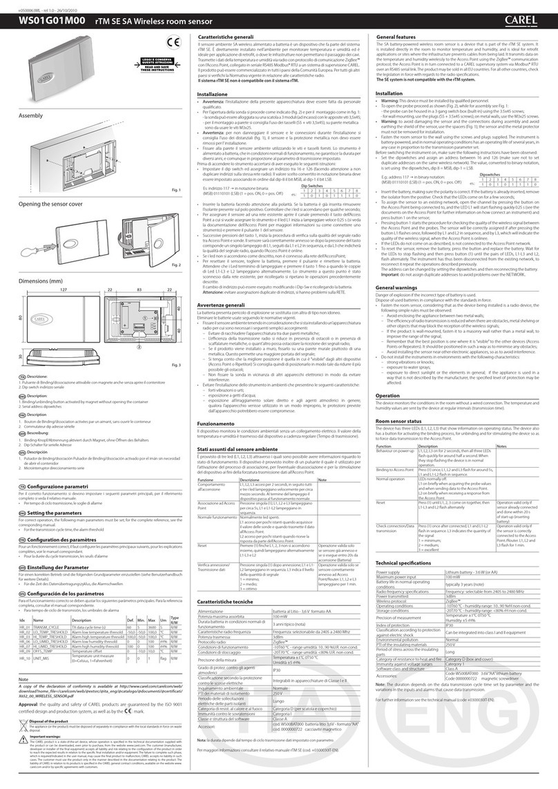
Carel WS01G01M00 User manual

Carel

Carel WS01G01M00 User manual

Carel uboss Manual

Carel

Carel uboss Manual

Carel boss micro BMBST00DP0 Installation instructions

Carel

Carel boss micro BMBST00DP0 Installation instructions

Carel uC2 User manual

Carel

Carel uC2 User manual

Carel PlantVisor Embedded Manual

Carel

Carel PlantVisor Embedded Manual

Carel PlantVisorPRO User manual

Carel

Carel PlantVisorPRO User manual

Carel emeter1 User manual

Carel

Carel emeter1 User manual

Carel mboss User manual

Carel

Carel mboss User manual

Carel PGD1000F 0 Series User manual

Carel

Carel PGD1000F 0 Series User manual

Carel WS01F01M00 User manual

Carel

Carel WS01F01M00 User manual

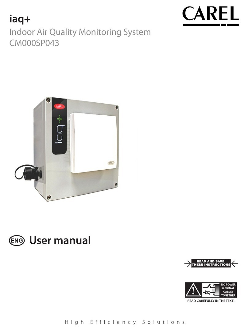
Carel iaq+ User manual

Carel

Carel iaq+ User manual

Carel iaq+ User manual

Carel

Carel iaq+ User manual

Carel HYPA 3 Series User manual

Carel

Carel HYPA 3 Series User manual

Popular Measuring Instrument manuals by other brands

Tenma 72-7800 user manual

Tenma

Tenma 72-7800 user manual

ICP DAS USA PMC-523 Series user manual

ICP DAS USA

ICP DAS USA PMC-523 Series user manual

Ceyear 4957D quick start guide

Ceyear

Ceyear 4957D quick start guide

PIE piecal 334 operating instructions

PIE

PIE piecal 334 operating instructions

Fisher Scientific accumet XL150accumet XL200accumet XL250accumet XL500accumet... reference guide

Fisher Scientific

Fisher Scientific accumet XL150accumet XL200accumet XL250accumet XL500accumet... reference guide

Hanna Instruments HI 96812 instruction manual

Hanna Instruments

Hanna Instruments HI 96812 instruction manual

Dranetz HDPQ-DN-MZP Quick reference guide

Dranetz

Dranetz HDPQ-DN-MZP Quick reference guide

Sartorius MA150C-000115V1 operating instructions

Sartorius

Sartorius MA150C-000115V1 operating instructions

Tecfluid LS Series instruction manual

Tecfluid

Tecfluid LS Series instruction manual

koban KRB-01 manual

koban

koban KRB-01 manual

Lovato DME D120 T1 instruction manual

Lovato

Lovato DME D120 T1 instruction manual

Megger torkel 820 user manual

Megger

Megger torkel 820 user manual

Pessl METOS CLIMA LoRa user manual

Pessl

Pessl METOS CLIMA LoRa user manual

Endress+Hauser Prosonic M Series manual

Endress+Hauser

Endress+Hauser Prosonic M Series manual

LUDLUM 14C manual

LUDLUM

LUDLUM 14C manual

NARDA RadMan 2LT operating manual

NARDA

NARDA RadMan 2LT operating manual

OPW Counterbalance 788 Series manual

OPW

OPW Counterbalance 788 Series manual

Master Meter Sonata user manual

Master Meter

Master Meter Sonata user manual

manuals.online logo
manuals.online logoBrands
  • About & Mission
  • Contact us
  • Privacy Policy
  • Terms and Conditions

Copyright 2025 Manuals.Online. All Rights Reserved.