CareRay CareView 750Cw User manual

Page 1 of 57
RD-OI-20 A/3
X-ray Flat Panel Detectors
CareView 750Cw/
CareView 750C
Operation Manual
Before using this detector, be sure to review this manual, as well as the manuals
of other devices in the system. Store the manual in an easily accessible location.

Page 2 of 57
RD-OI-20 A/3
Revision History
Version
Date
Description
A/0
2016.03.07
Initial release
2016.11.21
Add the typical patient doses
A/1
2017.08.24
Adjust the structure and update the description
2018.7.19
Update company name
A/2
2019.5.9
Update the chapter 11.5 EMC and EU information
A/3
2019.10.18
Update to add two power box CP- S304A and CP- S305A

Page 3 of 57
RD-OI-20 A/3
Attention
Copyright by CareRay Digital Medical Technology Co., Ltd. All rights reserved.
No part of this document may be reproduced, translated, or transmitted without the express written
permission of CareRay Digital Medical Technology Co., Ltd.
CareRay reserves the right to change the specifications, configuration and appearance of the product
without prior notice.
CareRay is not liable for errors or omissions contained in this manual or for any damages incurred in
connection with furnishing or use of this manual.
This manual is intended to help Original Equipment Manufacturers (OEM) in the installation and its
first operation. It also provides information for service and safety operation. The figures and data given
in this manual can’t be considered to be a contractual specification.
CareRay does not distribute the detector to the end-users but only to OEM or retrofitters who are
responsible of the installation of the detector into the radiography system. The system manufacturer or
retrofitter is also responsible of the validation of the detector performance for the foreseen application.
Please read this manual carefully before performing any installation or use of the detector. Consult
CareRay for additional information.

Page 4 of 57
RD-OI-20 A/3
General Safety Information
Follow all safety protocol in this manual and all warnings printed on warning labels. Ignoring such
protocol while handling the detector may result in accident or injury. Be sure to read and fully
understand the manual before operating the detector to avoid any unnecessary damage or personal
harmful.
Caution: Federal law restricts this product to sale by or on the order of a physician or a licensed
practitioner.
Warning: Users are responsible for the use and maintenance of the product. The product must only be
used by qualified personnel who are familiar with the operation of electrical equipment.
Warning: X-ray imaging, image processing, image acquisition, and data storage must be performed in
accordance with the law of the country in which the product is used. The user is responsible for
maintaining the privacy of image data.
Warning: This product may malfunction when exposed to electromagnetic waves. Keep away from
the environments with strong magnetic fields.
Warning: This product must be connected to an appropriate power source recommended by CareRay
to avoid unnecessary risks.
Warning: To avoid the risk of electric shock, this product must only be connected to supply mains
with protective earth.
Warning: This product should only be used with the original power cords. Inspect power cords and
connectors regularly. Cord and connector repairs should only be serviced by qualified personnel.
Warning: The SIP/SOPs (Signal input/output part) are to connect to certified IEC60601-1and IEC
60950-1equipment only.
Warning: In the event of any abnormal phenomenon such as smoke, fumes, strange sounds, an
accident or malfunction; immediately turn off the power of each device, unplug the power cable from
the AC outlet, and contact your dealer, distributor, or CareRay support. Further use may be dangerous.
Warning: Install the detector on a flat, stable surface. If the detector is installed vertically or tilted, the
detector must be securely fastened in that position. It may cause injury if dropped.
Warning: Ensure that the built-in foldable handle is secured tightly when the detector is fixed into the
bucky.
Warning: Do not hold the detector by hand during normal use.
Warning: No modification of this product is allowed.
Warning: Do not modify this product without authorization from the CareRay.
Warning: If this product is modified, appropriate inspection and testing must be conducted to ensure
continued safety of the product.

Page 5 of 57
RD-OI-20 A/3
Warning: Incorrect disposal of this product may adversely affect personal health and local
environment. When disposing, be sure to follow disposal protocol in compliance with local laws and
regulations.
Battery and Charging Dock Safety Information
Before using the battery and charging dock dedicated to CareRay wireless detector, read all applicable
warnings and cautions. Not following these instructions could result in electrical shock, fire, explosion
or other conditions which may cause death, injury or property damages.
Warning: Do not use other batteries that are not the dedicated battery for the detector.
Warning: Do not use other charging docks that are not the dedicated charging dock. Use of
nonstandard charging dock may result in battery explosion or leak.
Warning: Do not operate the charging dock using any type of power supply other than the one
indicated on the rating label.
Warning: This detector configures a plug-in battery. Do not modify or change the inner battery,
otherwise the battery may damage or ignite.
Warning: The change of battery must be operated by a qualified engineer.
Warning: Use the dedicated charging dock. Otherwise, a battery explosion or a battery leak may occur,
resulting in fire or electrical shock.
Warning: Stop using the battery immediately if it emits smoke, a strange smell, or otherwise behaves
abnormally.
Warning: Do not expose the battery or charging dock to water or other liquids.
Warning: Do not attempt to use a battery that has deteriorated. Using a battery that has exceeded its
life cycle may lead to overheating, fire or explosion.
Warning: Remove the battery from the detector if the detector is not likely to be used for an extended
period of time.
Warning: Be sure to charge the battery periodically (once three month) if it is not used for an extended
period of time. The battery cannot be charged if it has been over discharged.
PediatricApplication
Caution: Use of equipment and exposure settings designed for adults of average size can result in
excessive radiation exposure for a smaller patient. Studies have shown that pediatric patients may be
more radiosensitive than adults (i.e., the cancer risk per unit dose of ionizing radiation is higher).
Unnecessary radiation exposure may be harmful to pediatric patients.
Warning: Each request should be reviewed by a pediatric radiologist prior to examination to ensure
the correct study is performed.
Warning: The technologist should adjust the radiation dose for the patient’s size accordingly when
acquiring diagnostic images.

Page 6 of 57
RD-OI-20 A/3
Table of Contents
Attention……………………………….………………………………………...………………....3
General Safety Information……………………….…………………………………………..........4
1Overview..........................................................................................................................................8
1.1 Features.........................................................................................................................................8
1.2 Intended Use.................................................................................................................................8
1.3 Typical Patient Doses ...................................................................................................................8
1.4 Configuration................................................................................................................................9
2Product Description......................................................................................................................10
2.1 Components................................................................................................................................10
2.2 Detector....................................................................................................................................... 11
2.3 Power Box ..................................................................................................................................14
2.4 Charging Dock............................................................................................................................15
2.5 Li-Polymer Battery.....................................................................................................................16
3System Integration........................................................................................................................17
3.1 System Components ...................................................................................................................17
3.1.1 Typical Generator Specifications........................................................................................17
3.1.2 Detector Operation Conditions...........................................................................................18
3.1.3 Workstation (Recommended).............................................................................................19
3.2 X-ray Sync Mode........................................................................................................................19
3.2.1 External Sync Mode ...........................................................................................................19
3.2.2 Software Sync Mode...........................................................................................................20
3.2.3 Manual Sync Mode............................................................................................................. 21
3.2.4 F2AED.................................................................................................................................23
3.3 Network Connection and Power Supply.....................................................................................23
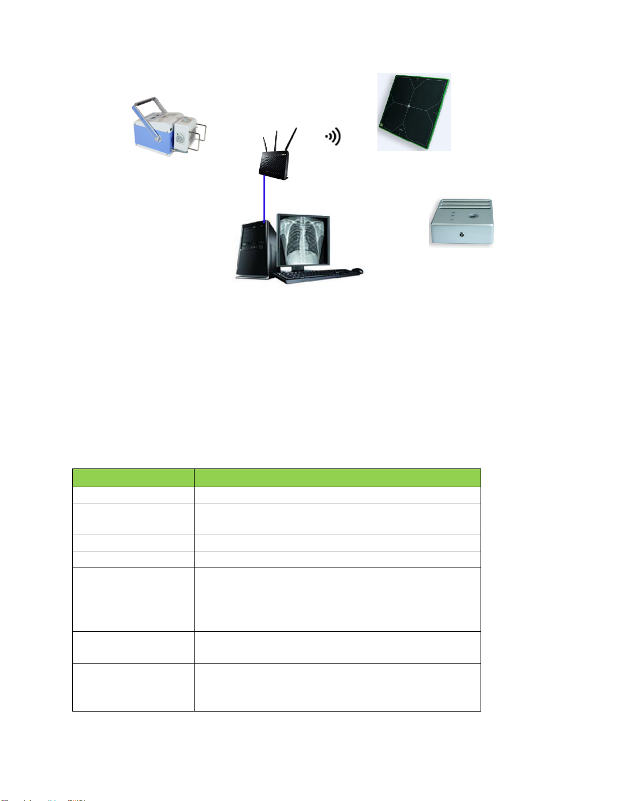
3.3.1 Wireless Connection Powered by Battery ..........................................................................23
3.3.2 Wireless Connection Powered by Power Box....................................................................24
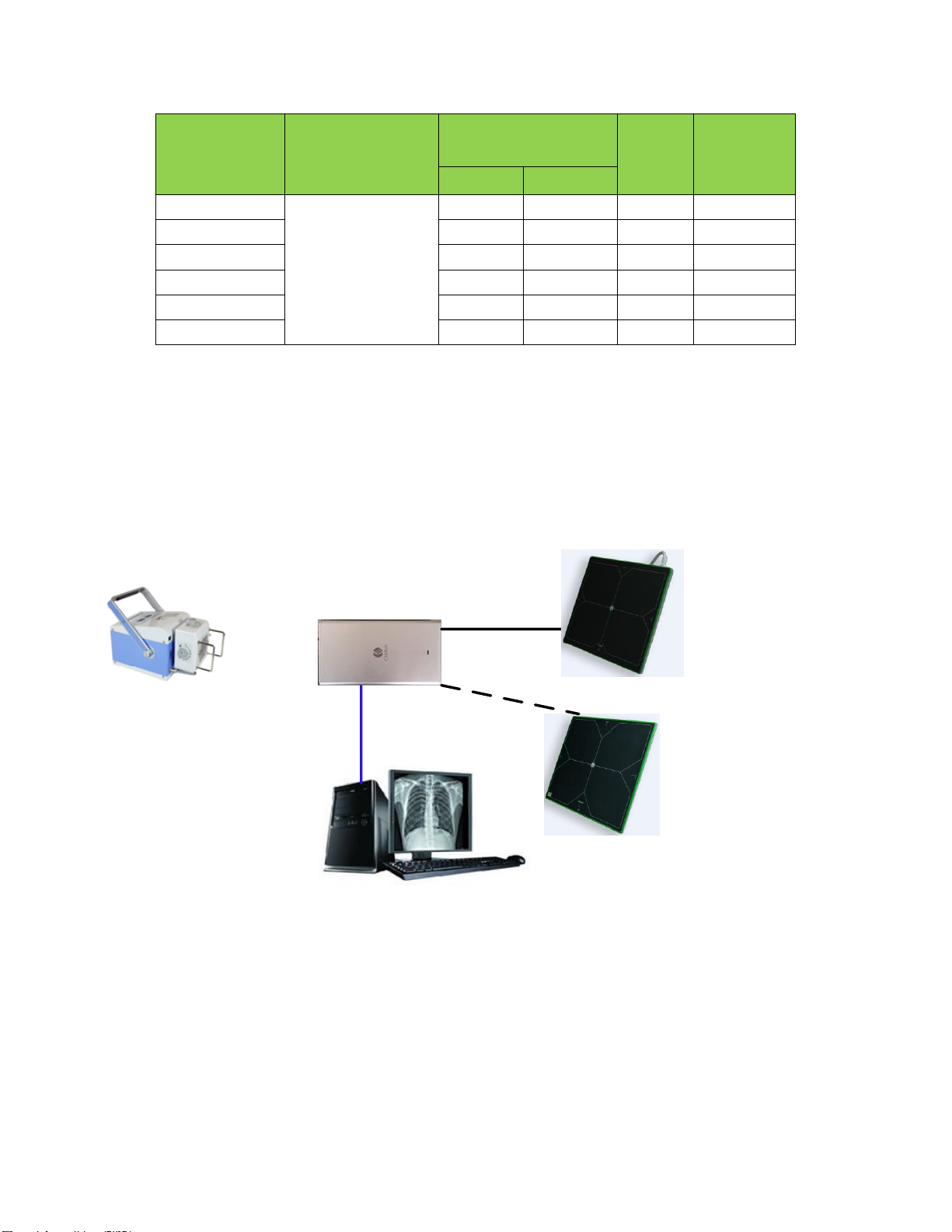
3.3.3 Wired Connection...............................................................................................................24
4Installation.....................................................................................................................................25
4.1 Unpacking...................................................................................................................................25
4.2 Hardware Installation..................................................................................................................27
4.2.1 CareView 750Cw................................................................................................................27
4.2.2 CareView 750C...................................................................................................................29
4.3 Network Configuration...............................................................................................................32
5Wireless Communication .............................................................................................................35
5.1 Architecture ................................................................................................................................35
5.2 Specification...............................................................................................................................36
5.3 Initial Setting ..............................................................................................................................36
5.4 Detector Wireless Information....................................................................................................37
5.5 Wireless LAN Diagnostics .........................................................................................................39
5.6 Intended Use Environment.........................................................................................................40

Page 7 of 57
RD-OI-20 A/3
6Announcement ..............................................................................................................................40
6.1 Basic Notices..............................................................................................................................40
6.1.1 Use-method of Power Supply.............................................................................................40
6.1.2 Network ..............................................................................................................................40
6.1.3 Electromagnetic Radiation.................................................................................................. 41
6.1.4 Contraindication .................................................................................................................41
6.2 Particular Notices........................................................................................................................ 41
6.2.1 Personnel............................................................................................................................. 41
6.2.2 X-ray Scope ........................................................................................................................41
6.2.3 Operation Conditions.......................................................................................................... 41
7Maintenance..................................................................................................................................42
7.1 Inspections..................................................................................................................................42
7.2 Maintenance................................................................................................................................43
7.3 Cleaning......................................................................................................................................44
7.4 Emergency..................................................................................................................................44
7.5 Maintenance Note.......................................................................................................................45
8Storage and Transportation.........................................................................................................45
8.1 Storage........................................................................................................................................45
8.2 Transportation............................................................................................................................. 45
9Specifications.................................................................................................................................46
9.1 Detector.......................................................................................................................................46
9.2 Power Box ..................................................................................................................................47
9.3 Charging Dock............................................................................................................................48
9.4 Li-Polymer Battery.....................................................................................................................49
10 Disposal..........................................................................................................................................50
11 Regulatory Requirements ............................................................................................................ 50
11.1 Product Classification.............................................................................................................50
11.2 Standards................................................................................................................................. 51
11.3 Symbols ..................................................................................................................................51
11.4 FCC Rules............................................................................................................................... 52
11.5 Guidance and Manufacturer’s Declaration for EMC Directive.............................................. 53
12 Abbreviations................................................................................................................................56

Page 8 of 57
RD-OI-20 A/3
1Overview
The CareView 750Cw/CareView 750C detector is a class of digital X-ray flat panel detector that has an
imaging area of 244mm×307mm. The CareView 750Cw detector communicates with wireless and an
optional wired communication feature (Giga-bit Ethernet communication mode via connecting the
power box).
The detector functions by intercepting X-ray photons. Then the scintillator emits visible spectrum
photons that illuminate an array of photo detectors (a-Si) that create electrical signals. The electrical
signals are then digitally converted to display an image on the monitor.
The detector should be connected to a computer and X-ray generator to digitize X-ray images and
transfer radiography diagnostics.
1.1 Features
Supports wireless communication (IEEE 802.11a/b/g/n) and double frequency (2.4GHz/5GHz) for
CareView 750Cw.
10"x12" cassette-size detector easily fits into standard bucky tray cabinets to upgrade old systems,
while also fitting many general radiography imaging systems.
Designed for portability and stability on uneven terrain with its lightweight design, simple wiring,
rubber-insulated frame, and high-strength aluminum-alloy case.
No not need to be connected to generator due to patented Full-Field Automatic Exposure Detection
(F2AED) Technology.
High capacity battery and low-power operation ensure hundreds of X-ray shots in a single-charge.
1.2 Intended Use
The CareView 750Cw/CareView 750C detector is indicated for digital imaging solution designed for
providing general radiographic diagnosis of human anatomy. It is intended to replace radiographic
film/screen systems in all general-purpose diagnostic procedures. This product is not intended for
mammography applications.
1.3 Typical Patient Doses
Typical patient dosage is shown in the table on the following page. Results may vary in practical
conditions.

Page 9 of 57
RD-OI-20 A/3
Table 1 Typical patient doses
Body part
Average adult
patient size
(with Anti-scatter
grid, 40 lp/cm 10:1)
SID(m)
Dose
(μGy)
kV
mAs
Chest, PA
Height: 170cm
Weight: 65kg
112
4
1.5
176
L-spine, AP
75
40
1
1770
Pelvis, AP
65
32
1
910
Hand, AP
50
2.5
1
38
Knee, AP
65
5
1
150
Foot, AP
50
2.5
1
38
Note:
PA: Postero-Anterior position; AP: Antero-Posterior position
Dosage amount is typical for average-sized adult patients.
1.4 Configuration
CareView 750Cw detector supports both wired and wireless configurations, while CareView 750C
detector only supports wired configuration, as illustrated below.
Figure 1 Wired configuration
X-ray System
Generator
DROC Workstation
Power Box
Gigabit LAN cable
Interface cable
CareView 750C
CareView 750Cw

Page 10 of 57
RD-OI-20 A/3
X-ray System
Generator
DROC Workstation
Router
Charger Dock
CareView 750Cw
Figure 2 Wireless configuration
2Product Description
2.1 Components
The product consists of a detector, Li-Polymer battery, power box, charging dock, software and
accessories.
Table 2 Components
Item
Description
Detector
Model: CareView 750Cw
Li-Polymer battery
(not connected)
Model: 4ICP/83/3/103
Power box
Model: CP-S303A or CP- S304A or CP- S305A
Charging dock
Model: CBC-ICP3B
Cables
AC Power cable (1.8m)
Interface cable (7m)
Gigabit LAN cable (7m)
24V DC power cable (3m)
CD, Program dongle
Software
Operation manual
Others
Certification
Warranty card
Packing list

Page 11 of 57
RD-OI-20 A/3
Item
Description
Detector
Model: CareView 750C
Power box
Model: CP-S303A or CP- S304A or CP- S305A
Cables
AC Power cable (1.8m)
Interface cable (5.68m)
Gigabit LAN cable (20m)
Synchronization cable (13m)
CD, Program dongle
Software
Operation manual
Others
M4 bolts (6pcs)
Certification
Warranty card
Packing list
Note: The AC power cable must adhere to local regulations of the country where the product is used.
Otherwise, a UL-approved power cable must be used.
2.2 Detector
The main task of the detector is to capture radiography images, which in turn will be transmitted to the
DROC (Digital Radiography Operator Console) workstation through wired or wireless connection.
An overview of CareView 750Cw detector is shown in figure below and on the following page.
Front view Back view
○
3
①
○
2
○
4

Page 12 of 57
RD-OI-20 A/3
Side view
Figure 3 Detector
Table 3 Description of detector
The overview of CareView 750C detector is shown in the figure on the following page.
No.
Name
Description
○
1
Carbon fiber plate
Low density, low X-ray absorption and high intensity
protection layer
○
2
Battery
Supply electrical power to the detector while
communicating wirelessly
○
3
Wifi antenna
Transmits data with wireless communications
○
4
Detector label
Display the information of detector
○
5
I/O interface
Allows the detector to communicate with power box via
interface cable
○
6
Power button
Press to power on or off the detector
○
7
Power LED
ON: Indicates power on status. (Green)
OFF: Indicates power off status.
○
8
Network LED
Blinking: 802.11 wifi mode (Blue)
OFF: 802.3 cable mode
○
9
Charging LED
ON: Battery charging (Orange)
ON: Charged complete (Green)
Blinking: Battery discharging, but electricity isn’t enough
(Orange)
OFF: Battery discharging, but electricity is enough.
○
5
○
7○
8○
9
○
6

Page 13 of 57
RD-OI-20 A/3
Front view Back view
Side view
Figure 4 Detector
Table 4 Description of detector
No.
Name
Description
○
1
Carbon fiber plate
Low density, low X-ray absorption and high intensity
protection layer
○
2
Detector cable
Connects to power box to communicate and supply power
○
3
Mounting holes
Used for fixing the detector
○
4
Detector label
Display the information of detector
○
5
Power LED (Green)
Indicates power on/off status.
The LED will display a green light when the device is
powered on.
○
6
Exposure LED (Yellow)
Indicates Exposure (X-ray on/off) status.
The LED will display a yellow light during exposure.
○
7
Error LED (Red)
Indicates detector works status.
The LED will display a red light when a work error
occurs.
○
2
①
○
3
○
4
○
5○
6○
7

Page 14 of 57
RD-OI-20 A/3
2.3 Power Box
With wired connection, the power box provides the voltage a detector needs to operate properly.
Additionally, the user can connect the power box to charging dock to charge the battery.
Figure 5 Power box
Table 5 Description of power box
No.
Name
Description
○
1
AC power inlet
Input, 100~240V, 50/60Hz
○
2
Fuse holder
F2.5AL250V
○
3
Power switch
Turn on or off the power box
○
4
Port
DC +24V output
○
5
Sync
Provides connection to the X-ray generator
○
6
LAN
Provides Gigabit Ethernet communication between the workstation and
detector
○
4○
5○
6
○
1○
2○
3
○
7
○
8

Page 15 of 57
RD-OI-20 A/3
○
7
Power LED
(DC 24V)
Indicates status of power supply operation and connection
○
8
Power box label
Displays the information of power box
2.4 Charging Dock
Charging dock is connected with the power box to charge the battery. It can charge up to three batteries
simultaneously.
Figure 6 Charging dock
Table 6 Description of charging dock
No.
Name
Description
○
1
DC input
Connects the power box to supply electrical power to the battery.
○
2
Battery compartment
Insert the battery to charge.
○
3
Power indicator
Indicates the power on/off status.
(Green: Power on)
○
4
Charging indicator
Indicates the charging status.
(Blue: Charging, Green: Fully Charged)

Page 16 of 57
RD-OI-20 A/3
2.5 Li-Polymer Battery
The battery supplies power to the detector while in wireless connection mode. When operating, only
use the dedicated battery and charge it completely before use. To charge the battery, perform the steps
below.
1Connect one end of 24V DC power cable to the “PORT” of the power box, and the other end to
the DC input port of the charging dock.
2Connect the AC power cable with power box and power supply.
3Insert the battery into the charging dock.
4Open the power switch of the power box. And make sure the power LED of the power box and
charging dock are green indicating the presence of direct current (DC) power.
5Charging should begin automatically. Verify that the charge LED shows a blue light. Once the
battery is completely charged, the charge LED should show a green light.
6Once completely charged, gently pull the charged battery to remove it from the charging dock.

Page 17 of 57
RD-OI-20 A/3
Figure 7 Battery charging
Warning: Remove the battery after the charge LED shows a green light. Prolonged charging after the
battery is completely charged may result in overheating of the battery, causing the battery to explode or
ignite.
Note: Batteries are typically completely charged after approximately 3.5 hours. Time to complete
charge may vary depending on external temperature and remaining battery level.
When the battery is placed inside the detector and the detector is connected with the power box, the
battery will be automatically charged with the charging LED showing orange light.
3System Integration
3.1 System Components
A Digital Radiography (DR) system mainly contains three components.
X-ray generator, tube and subsidiary device
DROC image workstation and software
CareView 750Cw/CareView 750C detector and subsidiary device
3.1.1 Typical Generator Specifications
Energy range: 40~150kVp
mA range: 10~1000mA (depending on the generator power)
ms range: 10~6300ms to produce 0.1~1000mAs (depending on the generator power)
Note: To our best knowledge, the detector is compatible with X-ray generators that match the above
specifications. If you have any questions or concerns regarding compatibility for other generators,
please contact your distributor or CareRay support.

Page 18 of 57
RD-OI-20 A/3
3.1.2 Detector Operation Conditions
X-ray energy range
The detector operates at the following X-ray tube peak voltages:
X-ray tube peak voltages: Min = 40 kVp
X-ray tube peak voltages: Typ = 70 kVp
X-ray tube peak voltages: Max = 150 kVp
X-ray exposure range
The detector operates within the linearity specifications up to an X-ray exposure value of 100μGy.
The detector operates within the degraded linearity specifications above 100μGy and up to an
X-ray exposure value of 130μGy.
X-ray source position
The angle between the X-ray central propagation axis and the normal axis of the front-end
entrance plane taken at the centre point of the matrix should remain within the following range:
X-ray angle: Min = -45 deg
X-ray angle: Typ = 0 deg
X-ray angle: Max = +45 deg
The distance between the X-ray source focal spot and the front-end entrance plane (SID) should
remain within the following range:
SID: Min = 100 cm
SID: Typ = 135 cm
SID: Max = 180 cm
X-ray window duration
While the X-ray window duration can be functionally settled by the system over a wide range,
image quality can be directly impacted by X-ray window duration (due to leakage, noise, or lag).
The full performance of the detector is guaranteed for the following X-ray window range:
X-ray window duration: Min = 10 ms (TBC)
X-ray window duration: Typ = 500 ms (TBC)
X-ray window duration: Max = 2500 ms (TBC)

Page 19 of 57
RD-OI-20 A/3
3.1.3 Workstation (Recommended)
Table 7 Workstation
Item
Description
Operating system
Windows XP/Win7/Win10
Processor
Intel i5 or compatible withAMD processor
RAM
>6GByte
HDD
>80GByte
Network
Dual 1000Mbit
3.2 X-ray Sync Mode
Synchronous connection mode is the signal transfer mode between the X-ray generator, which sends
the X-ray, and the detector, which receives the X-ray. The sync mode of CareRay’s static detector
contains external sync, software sync, manual sync and F2AED modes.
CareView 750Cw-supported typical sync mode contains software sync, manual sync and F2AED
modes.
CareView 750C-supported typical sync mode contains external sync, software sync, manual sync and
F2AED modes.
Note: The detector can’t terminate x-ray exposure via communication with the generator.
3.2.1 External Sync Mode
The detector and X-ray generator communicates through synchronization cable to deliver a
synchronized exposure signal.
The sequence chart of external sync mode for a complete cycle of image acquisition is shown in figure
below.
Hand Switch 2nd Gear
GEN_SYNC_P
DET_SYNC_P
X-ray ON
pressed
Exposure Time
released
Integeration Time
Figure 8
Sequence chart
A typical configuration for external sync mode of a DR system integrated with CareView 750C is
shown in the figure on the following page.

Page 20 of 57
RD-OI-20 A/3
Gigabit LAN Cable
X-ray Tube
Shielded X-ray Room
DROC Workstation CareView 750C
Power Box
Interface Cable
AC 100V
-240V
X-ray Generator
Sync cable
Control Panel
Figure 9 External sync mode
3.2.2 Software Sync Mode
The detector communicates with an X-ray generator via the DROC workstation via a wired or wireless
network connection. Compared with the external sync mode, the software sync mode will cause a
delayed response.
The sequence chart of software sync mode for a complete cycle of image acquisition is shown in figure
below.
Hand Switch 2nd Gear
X-ray ON
pressed
Exposure Time
released
SOFT_SYNC_EXP_REQ
SOFT_SYNC_EXP_EN
Figure 10 Sequence chart
A typical configuration for software sync mode of a DR system integrated with CareView 750Cw is
shown in the figure on the following page.
This manual suits for next models
1
Table of contents
Other CareRay Medical Equipment manuals
Popular Medical Equipment manuals by other brands

Boscarol
Boscarol OB 2012 FA operating instructions

Sarstedt
Sarstedt Safety-Multifly instructions

Orliman
Orliman TP-6400 INSTRUCTIONS FOR USE AND PRESERVATION

Henry Schein
Henry Schein 900-8275 Instructions for use

Ergotron
Ergotron SV DC Power System user guide

BIO-MED DEVICES
BIO-MED DEVICES Crossvent-2i+ Operation & service manual