CareWise C-Trak Apollo User manual

C-Tra k Apollo
Wireless/Wired Gamma Probe
for radio guided surgery
User Manual

1.0 Introduction 3
1.1 C-Trak®Analyzer and Probe Introduction 3
1.2 C-Trak®Getting Started Guide 3 - 4
1.3 C-Trak®Quick Reference for Surgical Use 5
2.0 Getting acquainted with
the C-Trak®System 6
2.1 Front Panel 6
2.2 Bottom Panel 7
2.3 Right Panel 7
2.4 Accessing the Display Screens (Sections 1 - 14) 8 - 22
3.0 Calibration Guidelines 22
3.1 Isotope Check Source (Sections 1 - 2) 22
3.2 Check Source Holder Use 23
3.3 Performing Calibration (Systems Test) 23
4.0 Pre-Surgery Set Up 23
4.1 Before Power Is Turned On 23
4.2 Background Test 23
5.0 Sterile Practices, Cleaning,
and Disinfecting 24 - 27
6.0 Safety Considerations 28
6.1 Error Messages 28
6.2 Power Supply Requirements 28
6.3 Disassembly 28
6.4 Lithium-Ion Battery Care and Maintenance 28
6.5 Radioactive Concerns 29
6.6 Use of Electrosurgical Devices 29
6.7 Use of Accessory Equipment 29
6.8 Probe Handling Guidelines 29
7.0 Technical Specifications 30
7.1 Power / Probe Overload Cuto 30
7.2 LCD Display 30
7.3 Probe Cable Connector 30
7.4 Size 30
7.5 Weight 30
7.6 Finish 30
7.7 Mode of Operation 30
7.8 Serial Numbers 30
7.9 Environmental Limits 30
7.10 Label Legibility 30
8.0 Use of Optional Accessories 31
8.1 Apollo Handset 31
8.2 Apollo Charging Dock and Plug-In Charger 31
8.3 C-Trak®Apollo System Cart 31
8.4 Foot Pedal 32
8.5 Printer 32
8.6 Lechner Collimator 32
8.7 Indium Shield Assembly 32
9.0 International Symbols 33
Appendix A
Warranty, Receiving Examination, Returns and Repairs 34
Appendix B
Troubleshooting FAQ 35
Appendix C
Error Messages 36 - 38
Appendix D
EMC Precautions 39
Appendix E
Proof of Cleaning Statement 40
Appendix F
Care Wise Products List, Instructions
for Detaching C-Trak®Cable 41 - 42
Appendix G
Manufacturer’s Radioactive Material
Exempt Quantity Statement 42
Appendix H
Intended Use 43
Appendix I
Disposal Information 44
Appendix J
Contact Information 44
2|www.carewise.com
Contents

1.0 Introduction
1.1 C-Trak®Analyzer and Probe Introduction
The C-Trak®Apollo system has been designed to detect and
quantify the nuclear radiation from gamma emitting isotopes
ranging in energy emissions between 27-600 keV. A clear display
of numeric quantities and an audible signal convey an increase
or decrease in radiation detection allowing the surgeon to
localize radiolabeled tissue for excision. The latest model of the
Apollo system presents maximum flexibility for the User in being
able to operate in one of three modes:
1) Wired gamma probe.
2) USB wired connection of the OmniProbe via the Apollo handset.
3) Wireless connection of OmniProbe via the
Apollo handset using bluetooth technology.
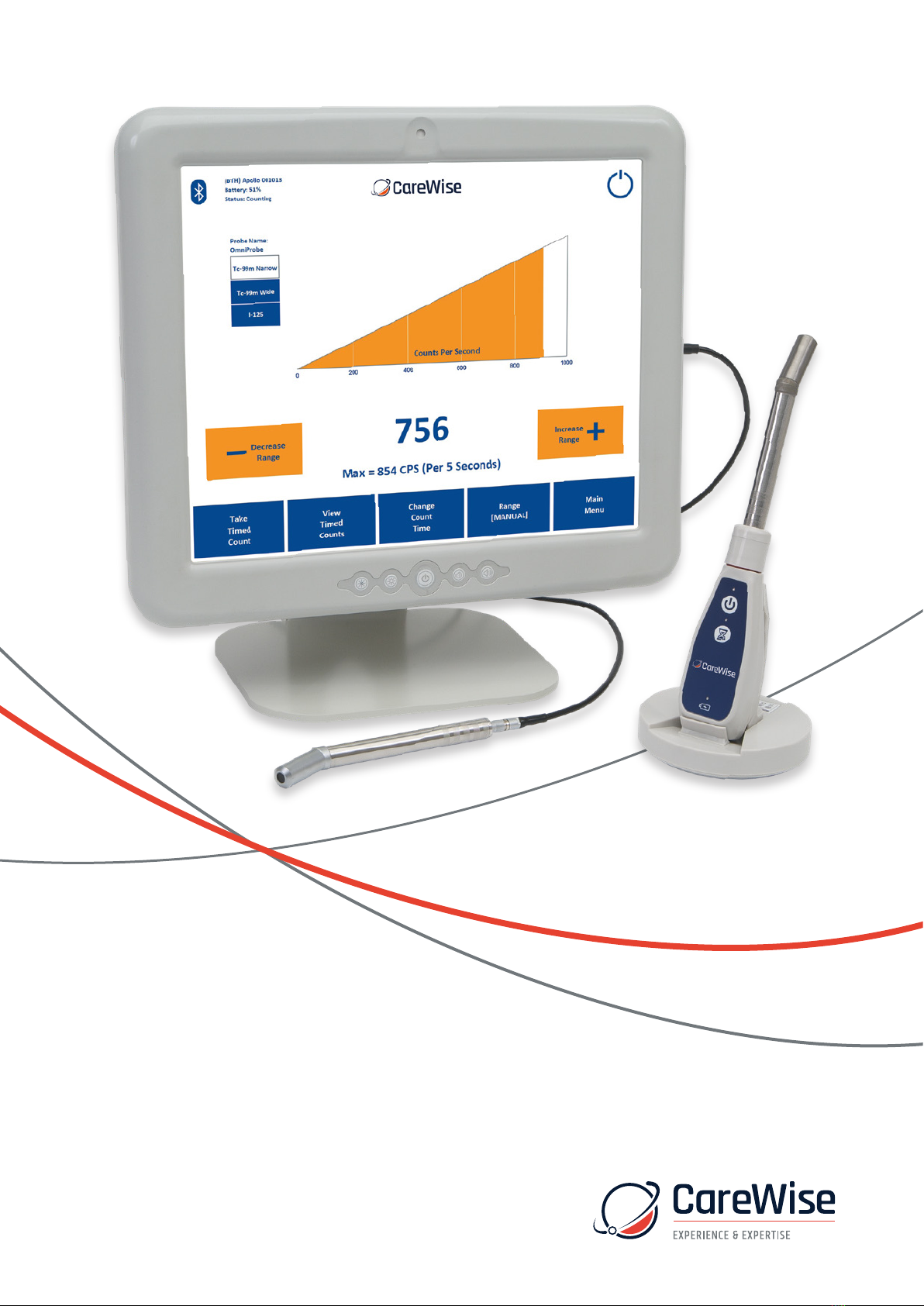
The system is comprised of the C-Trak®Apollo touchscreen
analyzer and one or more of the OmniProbe®family of probes.
The OmniProbe®and OmniProbe®-EL are capable of detecting
gamma ray energies up to 364 keV. The OmniProbe®-PET is
capable of detecting gamma ray energies up to 600 keV.
The analyzer is designed for operation with Care Wise designed
gamma probes. The analyzer may also be supplied with the
Apollo Wireless handset and/or foot pedal.
C-Trak®probes have special collimation and shielding that allow
highly directional detection of radiation from sites of interest,
along with greatly reduced detection of background radiation.
The analyzer is designed to operate the probe, display the data
from the detected radiation, and display and control the system’s
operating parameters. The result is optimum performance in
measuring gamma radiation from the photopeak of isotopes
such as Technetium-99m (Tc-99m), Indium-111 (In-111),
Iodine-125 (I-125) and Fluorine-18 ([F-18]-FDG) while
minimizing detection of Compton-scattered radiation.
The C-Trak®Apollo system meets ANSI/AAMI ES60601-1: A1:2012,
C1:2009/(R)2012 and A2:2010/(R)2012, CSA CAN/CSA-C22.2 NO.
60601-1:14, IEC 60601-1 Edition 3.1 (2012) / EN 60601-1:2006
+ A1:2013 + A12:2014 medical safety testing and certification
requirements. Its comprehensive shielding of high voltage sites
within the instrument eliminates the possibility of significant
electrical current leakage to patient or user under normal operating
conditions. The C-Trak®Apollo system has excellent electrical
safety; the system is designed to turn o the high voltage if the
current exceeds 10 µA, or if any short circuit is detected.
The system has been designed and manufactured for safe
operation in an operating room environment, as long
as flammable anesthetic gases are not used and
the system is not physically abused.
The C-Trak®Apollo CW4000 System is CE certified
and is fully compliant with FDA (21 CFR Part 820),
MDD (93/42/EEC) and CMDR
(SOR/98-282) requirements.
1.2 C-Trak®Getting Started Guide
(1) Attach the Monitor to the Stand. Place the stand on a flat,
stable surface. Slide computer onto stand carefully until
the ‘Quick Release’ bracket on the back of the computer
locks into the bracket on the stand. Alternatively, if using
an accessory cart, slide computer onto the bracket
mounted on the cart.
(2) Connect the Care Wise provided Power Cord. Check that
the power supply cables are free of any nicks, cuts, exposed
wires or other damage. Connect the power supply to the
computer and to an AC outlet. Turn on the power supply
with the switch on the back of the power supply. An
indicator light on top of the power supply should glow.
(3) Connect the Probe. Check that probe cable is free of any
nicks, cuts, exposed wires or damaged connectors. Connect
the probe to the monitor and then turn the power on using
the power button on the front of the monitor. [Reminder:
The OmniProbe®is a Type B Applied Part .]
The C-Trak®Apollo system takes a few minutes to start up
(boot) completely. Once the system displays the Count Screen,
(described in section 2.4-1), it is ready for use.
NOTE: To verify or reset the clock time if the system has been
relocated, press ‘Main Menu’, then ‘Setup’, then ‘Select Time
Zone’ to choose the time zone for your area.
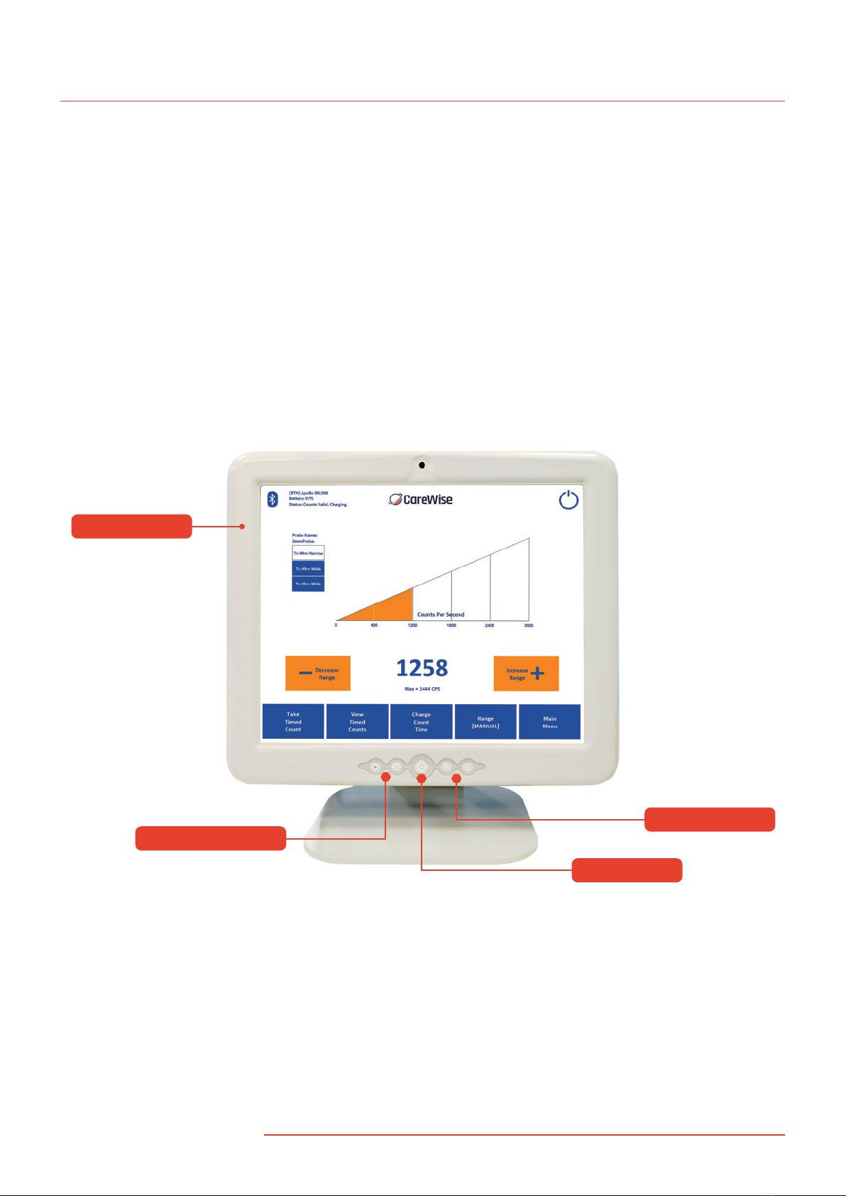
(1) Attach Monitor to Bracket
Slide computer monitor quick release bracket
over stand bracket until the tab locks into place.
(2) Connect Power Cord
(3) Connect Probe
Stand Bracket
Monitor Bracket
IMPORTANT
INFORMATION WARNING: No modification of this equipment is allowed.
Assembly of the C-Trak®Apollo System
3
1434

(4) Connecting the OmniProbe to the Apollo Wireless Handset
if not using the wired option.
To attach an OmniProbe to an Apollo Handset, first ensure
that the Apollo Handset is turned o; no LEDs will be
illuminated on the keypad:
Unscrew the probe clamp nut in an anti- (counter)
clockwise direction until the nut is loose but still
engaged with the thread:
Tighten the nut in a clockwise direction until the base
of the nut compresses the O-ring at the bottom of
the threaded section.
The Apollo Handset and OmniProbe many now be powered
on via pressing the ‘Power’ button located on the Apollo
keypad. The top LED will flash blue until the handset is
connected in the Apollo software (see Section 2.4-14).
Once connected, the top LED will be illuminated with
a steady blue light:
Carefully insert the OmniProbe through the clamp so
that the base of the probe comes into contact with
the LEMO connector mounted on the handset.
4|www.carewise.com
C-Trak Apollo

2. Ensure that:
a. The probe connected to the analyzer is
the probe listed on the Count Screen
[Image bottom left on this page].
b. The Isotope shown on the Count Screen
is the isotope that will be used.
3. Set RANGE at desired setting based on the expected
level of activity. A range of 0-100 is often preferred
for the initial survey [Figure 1].
4. Check VOLUME setting to ensure a
comfortable level [Figure 1].
5. Take background test [Section 4.2] to ensure
probe is free of contamination.
6. Use the probe to locate the area of greatest radiation
uptake of clinical interest before making the first incision.
7. In sentinel node procedures, always remain conscious of
the location of the injection site in order to dierentiate
between very high levels of radiation coming from the
injection site and radiation coming from the desired tissue;
e.g., sentinel lymph node itself. It can be helpful to mark
the patient’s skin to show the boundary of the very high
level radiation coming from tissue immediately
surrounding the injection site.
8. Move the probe slowly and avoid jerky movements.
With experience the user will develop a ‘feel’ for
the appropriate speed.
9. Detected count rates drop with the square of the distance
from tissue being viewed. Stay very close to the tissue
plane. While performing the initial survey, be careful not
to push the probe into the skin while moving it, as this
will also move the skin relative to the lymphatics.
The 5µCi Co-57 check source should be replaced every
18-24 months. Na-22 check source should be replaced
every 5 years. Check sources may be purchased through
Care Wise or your Care Wise distributor. See Product List,
Appendix F, for Product Codes.
Call Care Wise on +1-813-626-6848 (US & Canada)
+44 (0)1273 497600 (Europe & Worldwide) with any inquiry.
C-Trak®Apollo Count Screen
Before use the system should be calibrated using
the supplied test source. (See page 12)
To calibrate the system
This should be performed each day, before surgery.
The system should be properly connected up and
allowed to run for 5 minutes to warm up.
1. On the system test main
screen, ensure that the
correct probe is selected
(choose ‘select probe’).
Note: Not using the
correct probe will result
in the system storing the
calibration data against
the wrong probe’s serial number, so please select
the correct probe from the list, or add a new one
if your probe is not in the list.
2. Using the supplied radioactive source
holder with the correct source inside
(<2 years old for Co-57), insert the
probe fully into the source holder
until it reaches the end.
3. On the system test menu screen choose ‘perform
system test’. Follow the instructions given on the
screen to perform the system test (calibration).
4. Upon successful completion, (if no errors have
shown) the system is now ready for use.
Note: Ensure the probe and source holder are not moved
during the test. If the probe or source is moved during
the test, please repeat the test again.
1.3 C-Trak®Quick Reference for Surgical Use
1. Ensure that the Apollo Analyzer is securely attached to
the stand. Check that the power cable and probe cable
are free of any nicks, cuts, exposed wires or damaged
connectors. Ensure that the power box is on. Connect
probe, and then turn the Apollo power on, as in steps
1-3 in Section 1.2 If not using the wired probe connection,
ensure that an Apollo wireless handset has been connected,
powered on and connected in the software.
5

2.0 Getting acquainted
with the C-Trak®System
2.1 Front Panel [Figure 1]
(1) Display Screens – Depending on the specific screen selected,
displays the data on radiation detected by the system, the
specific configuration of the system when in use, or the
information needed to calibrate or reconfigure
the system as desired.
(2) Brightness Controls – Adjust the brightness
of the system’s display screen.
(3) Power Switch – Turns the system on. To shut down
press icon on top right hand side of the screen
(4) Volume Controls – Adjust the system volume.
Figure 1 – Front Panel of C-Trak®Apollo System
(1) Display Screen
(2) Brightness Controls
(3) Power Switch
(4) Volume Controls
C-Trak Apollo
6|www.carewise.com

2.2 Bottom Panel [Figure 2]
(1) Power – DC In Connection
• External, Universal AC input (100-240 vac 47-63 Hz),
100 watts, DC-out: 12 V, 8.33 A.
• For U.S. applications, the AC mains plug
is Hospital Grade, NEMA 5-15P-HG.
• Contact Care Wise or your Care Wise distributor
to supply or replace the proper AC mains
plug/cable for your application.
(2) USB Connectors – These are ONLY for use with Care Wise
approved peripherals (e.g. Care Wise approved accessory
printer, Apollo charging dock and foot pedal’ [Section 8.2]).
Attaching any devices not explicitly approved by Care Wise
(including keyboards, mice, other printers, etc.) can lead to
loss of functionality and system damage. DO NOT PLUG ANY
UNAPPROVED DEVICES INTO THE C-TRAK®Apollo SYSTEM!
All other ports will be blanked o with port
covers which must not be removed.
Figure 2 – Bottom Panel of C-Trak®Apollo System
2.3 Right panel [Figure 3]
Probe Connector – The analyzer connection is a MHV style
high-voltage connector for all Care Wise probes.
(NOTE: This is not a “BNC” connector.)
Figure 3. – Right Panel of C-Trak®Apollo System
(2) USB Connectors
(1) Power Cable Connection
Probe
Reminder: The OmniProbe®
is a Type B Applied Part
7

2.4 Accessing the screens
The C-Trak®Apollo is a touchscreen system. To change screens or
input data, select the desired field by touching the corresponding
‘button’ with your finger. The screen will respond to bare or gloved
fingers or other stylus and solid instruments. Please use caution
when using anything other than your finger. The screen can
be damaged. You may wish to use a clear plastic ‘screen
protector’ product.
Note: ‘Greyed out’ buttons indicate options that
are unavailable based on current settings.
Note: There may be dierences in the screen on your
analyzer from those presented here due to revisions
to the system software over time.
2.4-1 Count Screen
The first screen to appear when the system starts up is the
Count Screen, which displays feedback about the amount
of radiation the probe detects [Figure 4]. The features of
this screen are described below. Refer to Figure 4 and the
numeric reference for details.
(1) Rate Meter Display
• There are three versions of the RATE METER DISPLAY. The
default, shown in Figure 4, uses a wedge-shaped indicator
to show the amount of radiation detected. The other two
versions of the RATE METER DISPLAY are an analog
indicator and a histogram of counts per second over
time. These are shown in Figures 5 and 6 respectively.
• *NOTE: Tap the graphical indicator
to change the display type.
(2) Counts per Second Display – This numerical display indicates
the number of photons detected by the gamma probe per
second. Underneath the varying measured count rate value,
the maximum number of counts detected (in cps) is displayed;
this value is updated every 30 seconds. Tapping this area allows
you to change this to 5,10,15,20 or 25 seconds. When a new
maximum count rate is reached during a measurement,
the Counts per Second numerals will change from
blue to red temporarily.
(3) Range Controllers – The DECREASE RANGE and INCREASE
RANGE controllers are used to adjust the range of counts
per second displayed. Ranges of 0-100, 0-300, 0-600, 0-1000,
0-3000, 0-6000, 0-10000, 0-30000, 0-60000, 0-100000
are available.
(4) Take Timed Count Button – Pressing this button begins a
timed count for the current duration. While timed counts
are underway, they are viewed on the TAKE TIMED COUNTS
SCREEN. Details are in 2.4-2. The Timed Count operation may
also be started by pressing the Timed Count ‘Egg Timer’
button on the Apollo Handset keypad or by pressing
the foot pedal accessory.
(5) View Timed Counts Button – Pressing this button allows
the user to view any data for timed counts already taken.
Details are in 2.4-3.
(6) Change Count Time Button – Pressing this button
allows the user to change the duration of timed counts.
Details are in 2.4-4.
Figure 5 –Count Screen with Analog Meter
Figure 4 –Count Screen with Wedge Meter
1
2
3
456 77 8
7910
3
11
C-Trak Apollo
8|www.carewise.com

Figure 6 – Change Count with Histogram
(7) Toggle between manual and auto-range – When the [AUTO]
ranging option is selected, the software will automatically
change the measurement range and associated sound pitch
to the optimal setting for the quantity of radioactivity being
detected at that point in time. The optimisation process
typically takes no more than five seconds.
(8) Main Menu Button – Pressing this button directs the
user to the MAIN MENU [Figure 11], described in 2.4-6.
(9) System Shutdown
(10) Probe Connection – (see section 2.4-14).
Figure 4 (Duplicated from page 7) – Count Screen with
Wedge Meter and highlighted Surgical Information
Window (Probe Information and Isotope Window Settings)
(If probe has not been calibrated in 30 days it will
prompt calibration).
(11) Surgical Information Window – This area of the screen
displays information about the current surgical procedure
including which probe and isotope are in use and what
detection range is selected.
Note: Three buttons on the main Counts screen
allow the isotope detection range to be toggled.
The top button sets the clinical isotope, the middle
is the Tc-99m wide setting which increases sensitivity
but at a compromise of directionality and the bottom
the customer User isotope. Details on setting these
isotopes can be found in Section 2.4-10.
11
9

2.4-2 Take Timed Counts Screen
On the Take Timed Counts Screen [Figure 7], a user can collect
information about how much radiation is detected over time.
In the lower corner is a countdown timer, which starts with the
duration of the timed count selected in 2.4-4; the default
duration is 10 seconds. Three seconds after the countdown is
complete, the user will be returned to the Counts Screen in 2.4-1.
The user can exit from the Take Timed Counts Screen by pressing
the “Exit” button. If the user chooses to exit while a count is being
taken, counting is interrupted and no data are saved. If the user
exits after the count is completed but before the 3-second
automatic return to the Counts Screen, the data from
the current timed count are saved.
NOTE: ID information entered on the View Timed Counts
Screen will be displayed above the timed counts list.
2.4-3 View Timed Counts Screen
On the View Timed Counts Screen [Figure 8], a user can see
the results of any timed counts that have been taken, edit ID
information for the data and print the results.
Viewing Timed Counts:
Each time a user presses the Take Timed Counts button on the
Count Screen (described in 2.4-1), and the user does not interrupt
the collection of timed count data by pressing the Exit button
(described in 2.4-2), data are retained about the amount of
radiation collected during that timed count. Data about timed
counts are retained on the View Timed Counts Screen until the
system is shut down, or until the user presses the “Clear”
button in the lower left corner, and confirms the choice
in the dialog box that appears.
Arranging Timed Count Fields:
There are eight fields on the View Timed Counts Screen which the
user can rearrange by touching the field name and sliding to the
left or right: Sample Number Location, Type, Timestamp, Duration,
Total Counts, Counts per Second, and Percent Primary.
Figure 7 – Take Timed Counts Screen
Figure 8 – View Timed Counts Screen
10 |www.carewise.com
C-Trak Apollo

2.4-3 View Timed Counts Screen (Continued)
Locking Timed Count Fields:
The user can lock the changeable fields by pressing the lock icon
in the upper, right-hand side. When the image of the padlock is
“open” [as in Figure 8], the fields can be rearranged. When the
image of the padlock is “closed”, the fields are locked in place.
Editing Timed Count Fields:
There are three user-editable fields in the View Timed Counts
Screen: ID, Location and Type. The user can edit the ID field by
pressing within the white area and, using the popup keyboard,
enter any defining ID to correspond with this data set. To set
Location and Type, select an entry to display a pop-up menu.
Select the appropriate option from the menu. For Location, the
options include: In Vivo –Left and Right, Ex Vivo –Left and
Right and Background Left and Right. For Type, the options
include: Sentinel, Primary, Tumor, and Other.
The ‘Primary’ option in the Type field should be selected for the
sentinel node with the highest amount of radioactivity in a given
set of timed count data. The C-Trak®Apollo system will
automatically calculate the percentage of the Primary’s activity
for all other timed counts, and display these percentages in the
“Percent Primary” field. Note that only one timed count can be
set as “Primary”; if another timed count is set to “Primary”, the
count previously labeled “Primary” will be relabeled “Other”.
Saving Timed Count Data:
On the C-Trak®Apollo system, the user can manually save a
Timed Count data set by pressing the “Save” button and entering
an appropriate and unique name for the data set. The user can
restore a previously saved set of timed count data by pressing the
“Load” button and selecting the appropriate file name.
NOTE: If the system is shut down without saving the Timed
Count data, all current data will be lost. If the system suers an
unexpected shut down (e.g. due to power failure), the option to
restore the Timed Count data will be presented the next time the
system is powered on. Pressing ‘Yes’ will restore the Timed Count
data to the summary table, accessible via the ‘View Timed Counts’
button. Pressing ‘No’ will remove the Timed Count data from the
system memory.
Printing Timed Count Data:
To print from the C-Trak®Apollo system, ensure that the printer
cable is plugged into the USB port and the printer is turned on,
then press print on the screen.
Please note only printers purchased from Care Wise
will work with the system.
Figure 8 – View Timed Counts Screen
11

2.4-4 Change Count Time Screen
On the Change Count Time Screen [Figure 9], a user can set the
duration of timed counts. The default is 10 seconds. The default
can be restored quickly by pressing the “Default” button.
The duration for timed counts can range from
1 second to 999 seconds.
2.4-5 Big Counts Screen
On the Big Count Screen [Figure 10], a user can receive enlarged
numerical feedback about the amount of radiation the probe is
detecting. To show the Big Counts Screen, press the numerical
measured count rate value on the Main Count Screen. To exit
from the Big Counts Screen, press any area on the screen.
2.4-6 Main Menu
‘The Main Menu [Figure 11], allows the user to navigate to the
Count Screen (described in 2.4-1), System Test Screen (described in
2.4-7), and Setup Screen (described in 2.4-8), and also allows the
user to change the audible count rate sound type and turn o the
C-Trak®Apollo System’s power using the “Shutdown” power icon,
(described in 2.4-13).
Figure 9 – Change Count Time Screen
Figure 10 – Big Counts Screen
Figure 11 – Main Menu Screen
12 |www.carewise.com
C-Trak Apollo

2.4-7 System Test Screen
On the System Test Screen [Figure 12], reached from the Main
Menu [Figure 11], a user can calibrate and test all functionality
of the Apollo system. When a user presses SYSTEM TEST, the
Apollo system will both calibrate and test the system.
IT IS ESSENTIAL THAT THE CORRECT PROBE BE SELECTED FOR
THIS PROCESS. If the wrong probe is selected, the system test
data will be inaccurate, because they will pertain to the wrong
probe. The probe must be inserted into a fresh (within 2 years
for Co-57; within 5 years for Na-22) check source and held
still to perform the test.
The C-Trak®Apollo system creates a database and stores
calibration data for each probe used. For a first-time calibration,
or to change to a dierent probe, select the probe to be used
through the SELECT PROBE button, as described in 2.4-9.
When a system test is performed, the C-Trak®Apollo system
compares the current performance of the selected probe with
the saved results of previous performances, to see if any
undesirable changes have occurred. A warning message
will appear if there are any issues with the probe or analyzer.
If a particular OmniProbe and Apollo Handset (where the latter
is being used) has not undergone a System Test for a period of
30 days, an indication will appear in the Main Counts screen
(Figure 12a). A System Test should be performed as soon as
possible if this notification appears. Once the System Test
has been performed, the notification will disappear.
See Appendix C for Error Messages.
2.4-8 Setup Screen
The Setup Screen [Figure 13], allows the user to navigate to
various screens used to set up or customize the C-Trak®Apollo
system. Users can navigate from here to the Select Probe,
Select Isotope, Set Time Zone, and Main Menu Screens.
The Setup Screen also displays important information about
the hardware, firmware, and software serial numbers and
version numbers, as well as information about the probe
and isotope currently selected.
Figure 12 – System Test Screen
Figure 13 – Setup Screen
Figure 12a – System Test Expiry warning
message in Main Counts Screen.
13

2.4-9 Select Probe Screen
The Select Probe Screen [Figure 14], can be reached from the
SYSTEM TEST Screen or the SETUP Screen. Select Probe allows
users with multiple probes to select which C-Trak®gamma probe
to use. Users can create new probe entries by selecting NEW or
choose a dierent probe with SELECT. All probe information
can be edited using the EDIT option.
To edit an existing probe profile, select the probe to be edited
and press “Edit”. Both creating a new probe entry and editing
an existing one will bring up the Edit/Create Probe Screen,
shown in Figure 15 below. When finished, touch the “select”
button in the lower left corner of the screen. This will navigate
back to the System Test or Setup Screens.
Adding a New Probe or Editing Existing Probe Information
To create a new entry, select the Probe Type from the drop down
menu. Then select “Name” or “Serial #” to generate an on screen
keyboard and type in the new information. Press OK to save the
probe data. Multiple probe entries may be saved/retrieved on
the Apollo system along with the calibration data for each.
Pressing the OK button saves the changes and
returns to the Select Probe Screen above.
If a probe is no longer used with the system, Users can
remove this from the list by using the DELETE button.
Figure 14 – Select Probe Screen
Figure 15 – Edit/Create Probe Screen
14 |www.carewise.com
C-Trak Apollo

2.4-10 Select Isotope Screen
The Select Isotope Screen [Refer to Figure 16] allows the user to
quickly choose from a list of commonly used isotopes, based on
the type of probe currently selected.
(1) Clinical Isotope – Pressing this button brings up the Count
Screen preset to detect the most commonly used clinical
isotope associated with the type of probe selected.
The default settings for OmniProbe®and OmniProbe®-EL
devices, the clinical isotope is Tc99m. For OmniProbe®-PET
devices, the clinical isotope is 18F-FDG.
(2) Calibration Isotope – Pressing this button brings up the
Count Screen preset to detect the calibration isotope
associated with the type of probe selected. The default
calibration isotope for the OmniProbe®and OmniProbe®EL
devices is Co-57. For OmniProbe®PET devices, the calibration
isotope is Na-22. It is not necessary to select a calibration
isotope before performing a System Test, as the C-Trak®
Apollo System will automatically select the appropriate
calibration isotope for the selected probe.
(3) User Isotope – This button brings up the Count Screen
preset to detect the secondary isotope assigned by the user.
By default, it will display “User Isotope” and be grayed out
(unusable) until the user assigns an isotope to this shortcut
button by pressing the LIBRARY button and selecting an
isotope from the list. Press ASSIGN to save the isotope as
the User Isotope. Press SELECT to bring up the Count Screen
preset to detect the selected User Isotope.
(4) Isotope Library – Pressing this button brings up the
ISOTOPE LIBRARY, a list of commonly used isotopes,
described in 2.4-10.1.
(5) Main Menu – Pressing this button allows the user to
navigate to the MAIN MENU, described in 2.4-6.
2.4-10.1 Isotope Library Screen
The Isotope Library [Figure 17] comes pre-installed with
commonly used isotopes. Users can freely create, edit and
delete their own isotope entries. The isotopes that come
pre-installed, (shown in red on the Isotope Library Screen)
cannot be edited or deleted. To create a new isotope entry,
press NEW. To edit or delete an existing (user-created) isotope
entry, select the entry then press EDIT or DELETE respectively.
To select an isotope, highlight the entry and press SELECT.
The isotope chosen will become the active isotope.
To assign an isotope to the USER ISOTOPE button, select the
entry from the list and press ASSIGN. Assigning a user isotope
allows the user to quickly select a commonly used isotope
without having to navigate to the full isotope library.
Figure 16 – Select Isotope Screen
Figure 17 – Isotope Library Screen
(1) Clinical
(2) Calibration
(3) User Isotope
(4) Isotope
(5) Main Menu
15

2.4-10.2 Edit/Create Isotope Screen
To create or edit an isotope entry from the Isotope Library Screen
(Section 2.4-10.1), selecting NEW will bring up the Edit/Create
Isotope Screen [Figure 18]. The user can enter the isotope’s full
name, as well as a shortcut name, threshold setting, window
setting, and primary photopeak using the on screen keyboard.
2.4-11 Set Time Zone Screen
The Set Time Zone Screen [Figure 19], reached from the
SETUP SCREEN [Figure 13], allows the user to select
the appropriate time zone.
Figure 18 – Edit/Create Isotope Screen
Figure 19 – Set Time Zone Screen
16 |www.carewise.com
C-Trak Apollo

2.4-13 Shutdown Screen
The Shutdown Screen [Figure 20] appears if the ‘power button’
icon in the top right-hand corner is pressed and allows the user
to turn o the Apollo System. Pressing ‘No’ will return the User
to whichever screen was live before the power button icon was
pressed. Pressing ‘Yes’ will shut down the system.
2.4-14 Probe Connection
Connecting to an Apollo wireless probe handset via USB or
Bluetooth can be achieved by pressing the icon in the top
left-hand corner of the main Counts screen (note icon may be
Bluetooth, USB or No Connection).
Note: When using the wired OmniProbe connection, the icon will
appear as the USB probe connection [Figure 22] due to the fact
that this mode of operation uses an internal USB connection.
Important Note: When delivered, the system will already be
paired to the supplied Apollo handsets. Any new handsets must
be paired by the manufacturer and cannot be done by the User.
Please contact your local representative or Care Wise directly for
further information.
Figure 20 – Shutdown Screen
Figure 21a – Main Count Screen showing the Bluetooth icon
for the active wireless Apollo handset mode of operation
Figure 21b – Main Count Screen showing the USB icon for
the active USB wired Apollo handset mode of operation
17

Figure 21c – Main Counts Screen showing the Cable icon for
the active wired OmniProbe mode of operation
Figure 22a – The Pair button should be pressed
to pair a new handset via Bluetooth
In order to pair a new Apollo handset with the system,
press the Pair button in the Available Devices screen.
Enter that day’s password (obtainable from Care Wise
Support: [email protected]om)
The system will search for devices automatically – when the
device with the correct serial number (shown on the underside
of the Apollo handset) appears, highlight the device and click
‘Next’. The newly paired device will appear in the system
device list once the list has been refreshed.
18 |www.carewise.com
C-Trak Apollo

Figure 22b – Enter the password obtained from Care Wise
Support using the on-screen keyboard
Figure 22c – Enter the password obtained from Care Wise
Support using the on-screen keyboard
Figure 22d – Add Device window showing
available devices that can be selected
19

Pressing the Icon will bring up the available connections screen
which will list all of the available Apollo devices that have been
previously linked to the Apollo system.
Each connection type is displayed in terms of six parameters:
Connection Type: Bluetooth (BTH)
Device Name: Apollo
Serial Number: S/N 001012
Connected COM port: COM23
Battery Charge Level: 21%
Figure 23 – Available connections screen
showing the list of available devices
Figure 24 – Information shown on screen when
the list of available devices is being scanned
after pressing the Refresh button
Figure 25 – Highlighted available
device after it has been pressed
Once the desired Apollo device has been listed, press the
corresponding line in the Available Devices table; this will
cause the line to be highlighted in orange:
20 |www.carewise.com
C-Trak Apollo
If the paired device is not listed, click ‘Refresh’ and the system will
scan for all available paired devices. Note: The OmniProbe must
be connected to the Apollo Handset and the latter be powered on
via the on/o button on the handset keypad before the system
scans for devices; the top blue LED on the handset keypad will
flash blue when looking for a connection.
Table of contents
Popular Industrial Equipment manuals by other brands

Schier Products
Schier Products GB-15 Installation, operation and maintenance guide

PAW
PAW MB3.10 Assembly, installation and operation instructions

ABB
ABB HT845076 Operation manual

TruSteel
TruSteel AV15 installation manual

Sic Marking
Sic Marking ec7 user guide

Siemens
Siemens SIMATIC NET SCALANCE M-800 Getting started