Zakład Wytwórczy Aparatów Elektrycznych Sp. z o.o.
10
4. INSTALLATION AND ADJUSTMENT
Persons performing switching activities should have proper professional qualications and experience in ser-
vicing high-voltage equipment. When operating disconnector or its earthing switch (if installed) all health and
safety regulations in force at the place where they are installed have to be obeyed.
Before making a change (closing or opening) of the disconnector or its earthing switch one should ensure
that the adjustment is permissible, taking into account the conditions indicated above and the arrangement
conditions of the switchgear.
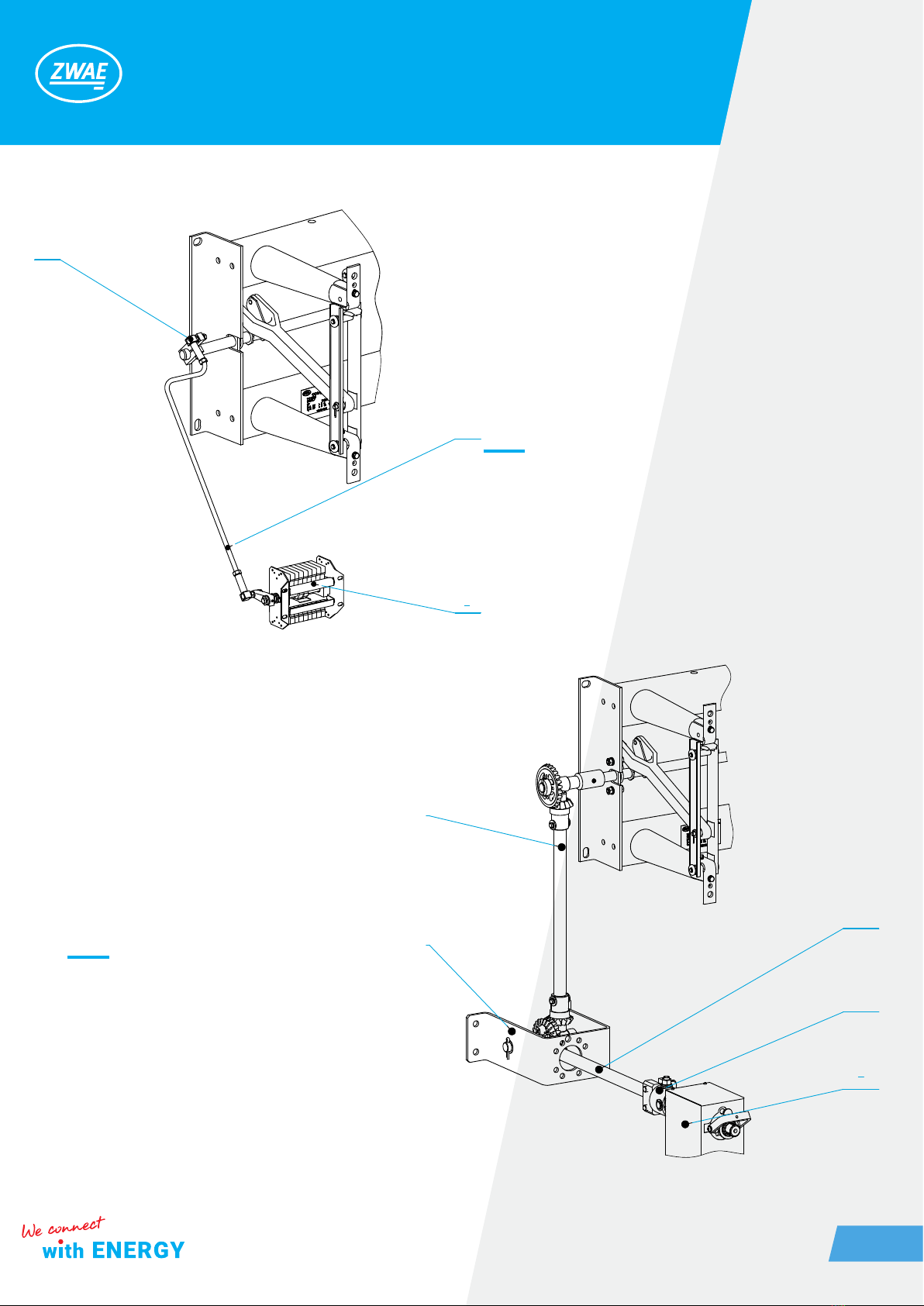
4.1. Preparation of the supporting structure and assembly of the disconnector
The OW type disconnectors are designed for operation in horizontal and vertical positions, with moving con-
tacts at the top. The design of the supporting structure should take into account the maintenance of appropri-
ate ground isolation distances, and the construction itself should have adequate stiffness.
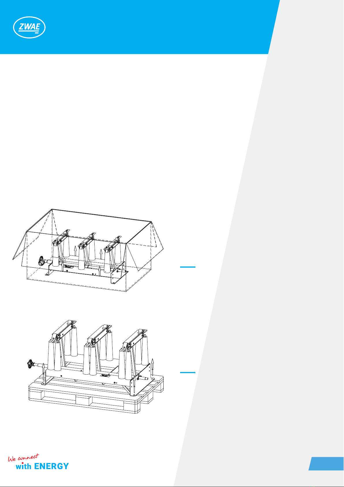
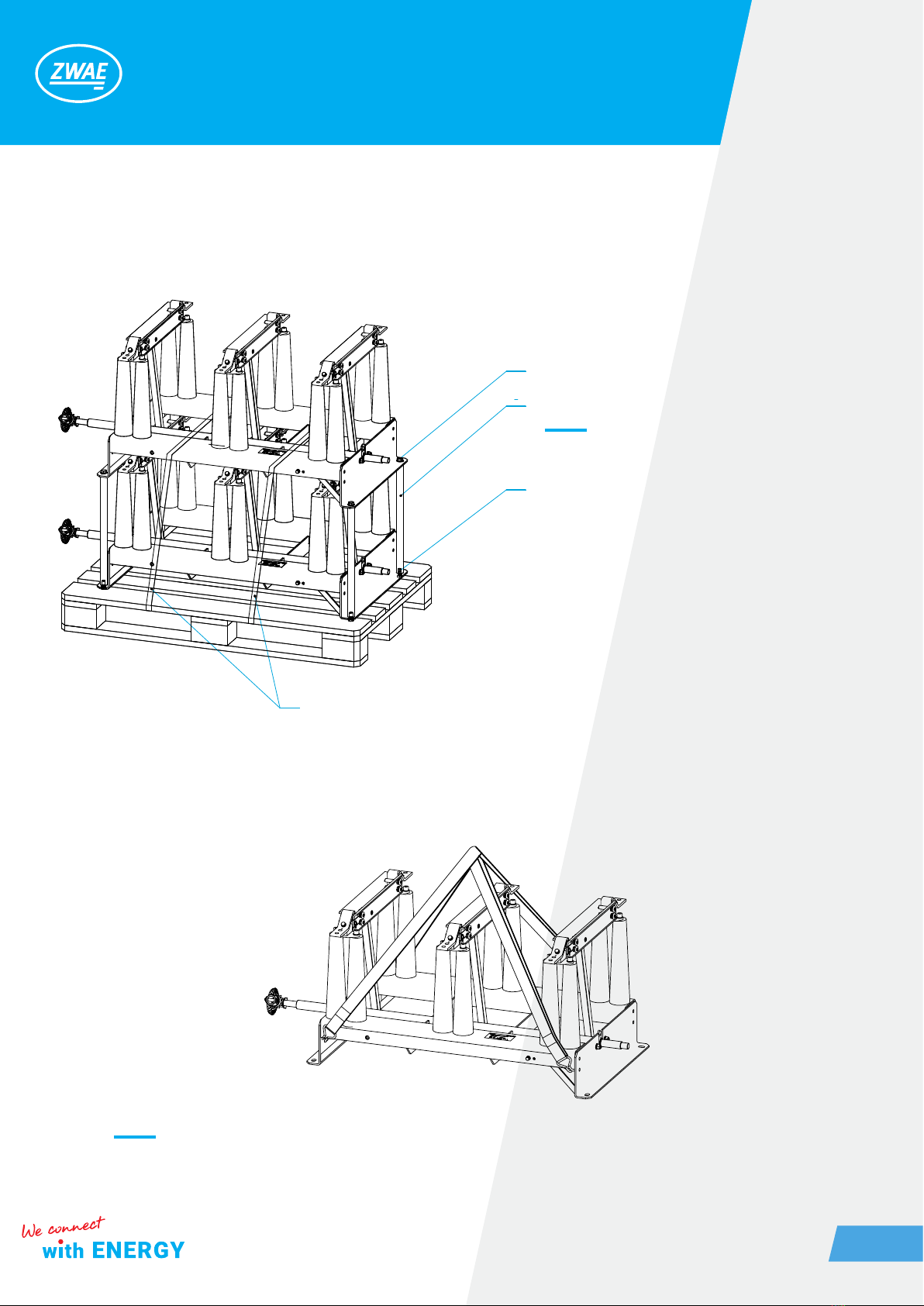
The base of the disconnector should be pre-screwed in three places (with three M12 bolts), and then place
possible washers under the base to level the plane of the supporting structure. The contact points of the sup-
porting structure with the disconnector base should lie in one plane (pos.2).
1. Elements of the supporting structure
2. The plane in which contact points of the suppor-
ting structure should be located
Figure 12. Installation of the disconnector to the suppor-
ting structure.
1 2