S&C TripSaver II User manual

September 12, 2022
© S&C Electric Company 2017-2022, all rights reserved Instruction Sheet 461-508LD
TripSaver® II Cutout-Mounted Recloser
Controller Module and USB Transceiver User Guide
Table of Contents
Introduction ................................ 2
Qualified Persons ........................... 2
Read this Instruction Sheet ................... 2
Proper Application .......................... 2
Retain this Instruction Sheet. . . . . . . . . . . . . . . . . . . 2
Safety Information .......................... 3
Understanding Safety-Alert Messages........... 3
Replacement Instructions and Labels ........... 3
Specifications .............................. 4
TripSaver II Cutout-Mounted Recloser Control
Module Integration ........................ 4
TripSaver II Cutout-Mounted Recloser USB
Transceiver.............................. 5
Hardware .................................. 6
Contents of TripSaver II Recloser Kit ............ 7
Inspection ................................. 8
Packing and Storage ........................ 8
Software ................................... 9
Downloading Software ....................... 9
Installing Software .......................... 9
Launching Software ......................... 9
Connect to a TripSaver II Recloser .......... 10
Controller Module Specifications ........... 14
Battery Information ..........................15
Appendix A ............................... 16
Regulatory Information .......................16

2 S&C Instruction Sheet 461-508LD
Introduction
WARNING
The equipment covered by this publication must be installed, operated, and maintained by
qualified persons who are knowledgeable in the installation, operation, and maintenance
of radios in electric power distribution equipment, along with the associated hazards. A
qualified person is a radio technician who is qualified to install transmission-power-limited
radio equipment per FCC Part 15 and who is trained and competent in:
• The skills and techniques necessary to distinguish exposed live parts from nonlive parts
of electrical equipment
• The skills and techniques necessary to determine the proper approach distances
corresponding to the voltages to which the qualified person will be exposed
• The proper use of the special precautionary techniques, personal protective
equipment, insulating and shielding materials, and insulated tools for working on or near
exposed energized parts of electrical equipment
These instructions are intended only for such qualified persons. They are not intended to
be a substitute for adequate training and experience in safety procedures for this type of
equipment.
NOTICE
Thoroughly and carefully read this Instruction Sheet before programming, operating, or
maintaining the TripSaver II controller module and USB transceiver.
WARNING
The equipment in this publication is only intended for a specific application. The application
must be within the ratings furnished for the equipment.
CAUTION
The controller module located inside the TripSaver II Cutout-Mounted Recloser is ONLY
intended for use inside the TripSaver II recloser and has not been approved for any other
use. DO NOT disassemble the TripSaver II recloser. Opening the recloser will void the
manufacturer's warranty, and could cause minor injury. There are no user-serviceable parts.
NOTICE
The controller module is located inside the TripSaver II Cutout-Mounted Recloser. It has
been evaluated for use only inside the TripSaver II recloser. Do not expose it to moisture. Do
not use it outside the TripSaver II recloser enclosure, and do not use it for any purpose other
than for which it is intended.
This instruction sheet should be available for reference wherever a TripSaver II controller module
and USB Transceiver are to be used. Retain this document in a location where it can be easily
retrieved and referred to.
Qualified
Persons
Read this
Instruction
Sheet
Proper
Application
Retain this
Instruction
Sheet

S&C Instruction Sheet 461-508LD 3
Safety Information
Several types of safety-alert messages may appear throughout this instruction sheet and on labels
attached to the TripSaver II Cutout-Mounted Recloser or in the TripSaver® II Service Center
Conguration Software. This document must be consulted in all cases where is marked to
determine the nature of the potential hazards and any actions that must be taken to avoid them.
Become familiar with these types of messages and the importance of these various signal words:
DANGER
“DANGER” identifies the most serious and immediate hazards that will likely
result in serious personal injury or death if instructions, including recommended
precautions, are not followed.
WARNING
“WARNING” identifies hazards or unsafe practices that can result in serious
personal injury or death if instructions, including recommended precautions, are not followed.
CAUTION
“CAUTION” identifies hazards or unsafe practices that can result in minor
personal injury if instructions, including recommended precautions, are not followed.
NOTICE
“NOTICE” identifies important procedures or requirements that can result in
product or property damage if instructions are not followed.
If any portion of this instruction sheet is not understood and assistance is needed, contact the
nearest S&C Sales Ofce or S&C Authorized Distributor. Their telephone numbers are listed on
S&C’s website sandc.com, or call the S&C Global Support and Monitoring Center at 1-888-762-1100.
NOTICE
Read this instruction sheet thoroughly and carefully before
configuring, installing or operating a TripSaver II Cutout-Mounted
Recloser.
If additional copies of this instruction sheet are needed, contact the nearest S&C Sales Ofce,
S&C Authorized Distributor, S&C Headquarters, or S&C Electric Canada Ltd.
It is important that any missing, damaged, or faded labels on the equipment be replaced
immediately. Replacement labels are available by contacting the nearest S&C Sales Office, S&C
Authorized Distributor, S&C Headquarters, or S&C Electric Canada Ltd.
Understanding
Safety-Alert
Messages
Replacement
Instructions
and Labels

4 S&C Instruction Sheet 461-508LD
Specications
TripSaver II Cutout-Mounted Recloser Control
Module Integration
Two electronic TripSaver II Cutout-Mounted Recloser
control modules (model numbers TSII-CONTRL5 and
TSII-CONTRL6) can integrate into the host self-powered
cutout-mounted, electronically controlled single-phase
recloser. The recloser uses a vacuum fault interrupter
technology and is offered in system class voltage ratings
of 15 kV and 25 kV.
The control module is an integral part of the TripSaver
II recloser, and S&C will install it at the factory. End-
users cannot do the installation themselves. Regardless
of the model, the control module resides in the TripSaver
II Cutout-Mounted Recloser’s housing, and each model’s
functions remain the same for all recloser configurations.
The control module processes all electrical functions
required for the proper operation of the TripSaver II
Cutout-Mounted Recloser.
Aside from its primary functions, the control module
can be wirelessly accessed by following the IEEE 802.15.4
protocol for performing maintenance. The control module
includes a radio transceiver, an antenna, and software.
Information regarding the 2.4-GHz radio is provided in
Table 1 . The communication protocol remains unaltered in
all TripSaver II Cutout-Mounted Recloser configurations.
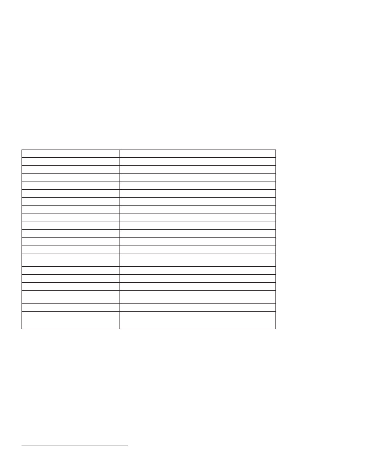
Table 1. Details of the TripSaver II Cutout-Mounted Recloser Control Module
Applicant S&C Electric Company
Brand Name TripSaver® II Cutout-Mounted Recloser
Product Model Name TripSaver II Control 5 and TripSaver II Control 6
Product Model Number TSII-CONTRL5 and TSII-CONTRL6
FCC Identifier U3D-TSIICONTRL6
IC Identifier 5349C-TSIICONTRL6
Dimension 6.53 in. (16.6 cm) x 5.198 in. (13.2 cm) x 2.98 in. (7.6 cm)
Weight 20 oz. (567 g) for TSII-CONTRL6 and 17.6 oz. (499 g) for TSII-CONTRL5
Technologies Supported by the Equipment Bluetooth Low Energy (Bluetooth 5), IEEE 802.15. 4 (Zigbee), Thread
Transmission Speed 250 kbps
Type of Transmission Digital Transmission System (DTS)
Rated RF Output 10.5 dBm (11.22 mW)
Frequency Range 2405 – 2480 MHz
Type of Modulation/Data Rate GFSK / 1 Mbit/s
O-QPSK / <200 kbps
Bandwidth 5 MHz
Number of Channel(s) 16 (from 11 to 26)
Antenna(s) and Gain PCB antenna, Gain: 3dBi
CT Voltage Input CT input 230 Vac, 2 A, 50/60 Hz
J10 input 11-14.5 Vdc, 1 A
Environmental -40°C (-40°F) to +40°C (+104°F).
Manufacturer Name and Address S&C Electric Company
6601 N Ridge Blvd.
Chicago, IL 60626

S&C Instruction Sheet 461-508LD 5
Specications
TripSaver II Cutout-Mounted Recloser USB
Transceiver
To enhance the wireless connectivity between the
TripSaver II recloser controller module and USB trans-
ceiver, S&C recommends the use of Taoglas External
antenna, model# GW.11.A153 (S&C part number 904-
002523-01) with USB transceiver part number FDA-1868R2.
This control module has been granted modular approval
for TripSaver II Cutout-Mounted Recloser applications.
The final host TripSaver II Cutout-Mounted Recloser and
control module combination have been evaluated in a
certified lab for FCC Part 15B criteria for unintentional
radiators to be properly authorized for operation as a
Part 15 digital device. S&C will provide a test report upon
request.
Control Module Models:
The TripSaver II Cutout-Mounted Recloser control module
provides controls and all logic functions for the proper
functionality of TripSaver II recloser. The control module
has two distinct models:
1. TripSaver II Control 5 (TSII-CONTRL5) has a main
control board that provides standard 5-second open
intervals during the TripSaver II recloser’s reclosing
sequence.
2. TripSaver II Control 6 (TSII-CONTRL6) provides
extended open interval functionality, enabling a
30-second open interval during the TripSaver II
recloser’s reclosing sequence. The main control board
has no sufcient storage energy to implement this
feature. Therefore, a battery and battery charging/
discharging circuitry has been added to supply
necessary energy to the control module.
Both TripSaver II Cutout-Mounted Recloser control
module models cause no changes to the recloser’s outer
enclosure. Overall integration and battery, battery board,
and main control board assembly is shown in Figure 1
Figure 1. The control module assembly.

6 S&C Instruction Sheet 461-508LD
Hardware
Figure 2. TripSaver II recloser kit contents.
Ac adapter Power outlet plug adapter TripSaver II Power Module
Extension cord for
ac adapter
USB transceiver with
PCB antenna
USB transceiver with External
Antenna Connector
External antenna
Carrying Case
User Guide
Blank adhesive labels
(transparent overlay also
included) for writing user-
configuration parameters. To
be attached to the left side of
the lower TripSaver II recloser
housing

Hardware
S&C Instruction Sheet 461-508LD 7
Contents of TripSaver II Recloser Kit
Figure 3. Cordless power module in carrying case. Must be used
by customers in the United Kingdom and European Union.

Hardware
8 S&C Instruction Sheet 461-508LD
Inspection
Examine the shipment for external evidence of damage as
soon after receipt as possible, preferably before removal
from the carrier’s conveyance. Check the bill of lading
to make sure the shipping skids, crates, and containers
listed are present.
If there is loss or visible damage:
1. Notify the delivering carrier immediately.
2. Ask for a carrier inspection.
3. Note the condition of shipment on all copies of the
delivery receipt.
4. File a claim with the carrier.
If concealed damage is discovered:
1. Notify the delivering carrier within 15 days of receipt of
shipment.
2. Ask for a carrier inspection.
3. File a claim with the carrier.
Also, notify S&C Electric Company in all instances of
loss or damage.
Packing and Storage
The TripSaver II Cutout-Mounted Recloser Cordless
Power Module comes in a foam-padded carrying case.
See Figure 3 on page 7. A 9-V battery is included. When
not in use, the cordless power module should be stored
in its carrying case. The carrying case should be stored
in a protected area, such as inside a truck or indoors in a
service center. Use care not to drop the cordless power
module during installation and removal.

S&C Instruction Sheet 461-508LD 9
Software
Downloading Software
The TripSaver II Service Center Configuration Software is available for download
only to customers who have purchased the configuration kit. For each configuration
kit purchased, the user is entitled to install and use TripSaver II Service Center Conguration
Software on no more than two computers at a time. The latest software release is posted on the
S&C Automation Customer Support Portal. A username and password are needed to log in to the
portal. A new S&C customer should complete the form in the lower section of the webpage and a
new username and password will be sent. If a password is already available, click on the Log-In
To Secure Site button. Enter the username and password to log in to the portal. Download the
installer SCC1.9_Installer.exe from the portal.
Installing Software
Double-click the downloaded installer le and follow the on-screen instructions. The installer will
automatically install Microsoft .NET framework onto the computer if the required .NET version is
missing. Administrative privileges are needed to nish the installation.
Launching Software
To launch the software, click on the green SCC 1.9 icon on the desktop or in the Start menu.
A warning screen will be displayed just after the software is launched. Read the message
carefully and understand the warning. Proceed by clicking on the green I have read and
understand the above warning button.
When the software is launched, settings can be configured and saved while in the Standalone
(offline) mode.

10 S&C Instruction Sheet 461-508LD10 S&C Instruction Sheet 461-508LD
Connect to a TripSaver II Recloser
DANGER
The TripSaver II Cutout-Mounted Recloser MUST
be de-energized and removed from the utility pole
before attaching the “corded” power module (power
module with ac adapter and extension cord) to the
base of the TripSaver II recloser. The corded power
module is ONLY intended to be used for setup and
data collection when the TripSaver II recloser is
de-energized and removed from the utility pole. (To
provide power to a TripSaver II recloser while it is
mounted to the pole, use the cordless power module,
S&C catalog number 5954.) Failure to remove the
TripSaver II recloser from the utility pole before
connecting the corded power module can cause
arcing, burns, electric shock, and death.
Follow these steps to connect to a TripSaver II recloser
to apply new settings:
STEP 1. Screw the threaded bottom of the antenna into
thethreadedconnectorontheUSBtransceiver.
See Figure 4.
STEP 2. Install the USB transceiver.
A USB transceiver (Firmware Version 1.6)
must be installed on the computer to com-
municate with a TripSaver II recloser. Insert
the USB transceiver into any USB port on
the computer. See Figure 5. The installation
process is automatic.
Note: The USB transceiver does not need to
be installed to install the software and to run
the software in Standalone (offline) mode.
STEP 3. Assemble the power supply and power up the
TripSaver II Recloser.
A TripSaver II recloser must be powered by
the power module to enable its communication
capability. Complete the following steps before
attempting to communicate with the TripSaver
II recloser.
(a) Plug the pin of the ac adapter into the
opening on the power module.
See Figure 6.
Figure 5. Plug the USB transceiver into the
computer.
Figure 6. Plug in the ac adapter pin.
Threaded
connector
Threaded-end
of antenna
Figure 4. Connecting the antenna to the USB
transceiver.

S&C Instruction Sheet 461-508LD 11
Connect to a TripSaver II Recloser
S&C Instruction Sheet 461-508LD 11
(b) Position the power module near the base of
the TripSaver II recloser, as shown in Figure
7; the module will be held in place
magnetically.
(c) Install the proper power outlet plug adapter
onto the ac adapter. See Figure 8.
(d) Plug the ac adapter into a wall outlet. See
Figure 9.
(e) To verify the TripSaver II recloser is
powered, rotate the MODE SELECTOR lever
and observe the LCD screen. If the LCD
screen begins to scroll, it indicates the unit
has been successfully powered.
The setup, at the end of Step 2, should look like the
picture in Figure 10.
Figure 8. Install the plug adapter.
Figure 9. Connect the ac adapter to a wall
outlet.
Figure 10. Completed TripSaver II recloser setup.
Figure 7. Position the power module.

12 S&C Instruction Sheet 461-508LD
Connect to a TripSaver II Recloser
12 S&C Instruction Sheet 461-508LD
STEP 4. A Transceiver ID unique to each TripSaver II
recloser is needed to establish communications
between the computer and the recloser. The ID
consists of a 32-digit character string in the
format of:
“0019C900.00020000._ _ _ _ _ _ _ _ . _ _
_ _ _ _ _ _”.
The TripSaver II Service Center Configuration
Software v1.10 will auto-detect the Transceiver
ID of TripSaver II reclosers with firmware
version 1.8 or 1.9. If connection difficulties are
encountered, or when connecting to a TripSaver
II recloser with firmware version 1.7 or earlier,
enter the Transceiver ID manually. The first 16
digits of the ID are pre-typed; only the last 16
digits must be entered.
The Transceiver ID for the TripSaver II
recloser can be obtained through the
following methods:
Method 1: The Transceiver ID is embedded
in the QR code laser-etched onto the lower
housing of each TripSaver II recloser. See
Figure 11. Download a free QR scanner app to
a smart phone and scan the QR code to obtain
the Transceiver ID.
Method 2: Rotate the MODE-SELECTOR
lever to initiate the Display screens after the
TripSaver II recloser is powered up. The LCD
screen will begin to scroll. The first screen
displayed contains the Transceiver ID. See
Figure 12.
Note: This screen does not appear when
communication is disabled or when no screens
are added to the Display screen sequence.
Method 3: The Transceiver ID is also printed
on the back of the yellow “DO NOT DROP—
HANDLE WITH CARE” tag attached to each
TripSaver II recloser when it leaves S&C Electric
Company. See Figure 13.
Figure 12. Transceiver ID on the TripSaver
II recloser LCD screen.
Figure 13. Transceiver ID on yellow
tag.
Last 16 digits here
Figure 11. The location of the QR code.
QR code

S&C Instruction Sheet 461-508LD 13
Connect to a TripSaver II Recloser
S&C Instruction Sheet 461-508LD 13
STEP 5. Connect to the device:
(a) To connect to a TripSaver II recloser, select
Connection> Connect to Device from the
main menu or click on the Connect to
Device icon in the quick access toolbar.
Make sure the USB transceiver is already
plugged into the computer.
(b) Next, a Transceiver ID Request dialog box
will open. Enter the Transceiver ID of the
TripSaver II recloser being connected to,
and click on the OK button to connect. The
rst 16digits of the ID are pre-typed, so only
the last 16 digits must be typed in. See Figure
14.
(c) During the connection process, a status bar
will be displayed. See Figure 15. Wait about
10 seconds for the connection process to
nish, or click on the Cancel button to
cancel the connection process.
(d) The Status screen will open after the
TripSaver II recloser is successfully
connected. See Figure 16. Existing settings,
status information, and event logs of the
TripSaver II recloser can now be viewed, or
new settings for the device can be applied.
Figure 15. The Connection status bar.
Figure 16. The recloser Status screen.
Figure 14. Enter last 16 digits into the
Transceiver ID dialog box.
Enter last 16 digits here

14 S&C Instruction Sheet 461-508LD
Controller Module Specications
The TripSaver II Cutout-Mounted Recloser contains
a controller module used to control the self-powered
recloser. The controller module processes all electronic/
electrical functions required for the proper operation of
the TripSaver II recloser. The controller can be wirelessly
accessed and configured via the IEEE 802.15.4 protocol.
See Figure 17 and Table 2.
EDCBA
Figure 17. Controller module pinout diagram for Table 1.
Label Description Voltage
AJ10, Input Connection●11-14.5 Vdc 1 A
BJ12, Rogowski Coil Connection 12 Vac , < 10 mA
CJ9, Dropout Control Connection 225 Vdc , 5 A
DJ8, VI Control Connection 225 Vdc , 5 A
EJ2, CT Input Connection 230 Vac , 2 A, 50/60
Hz
●J10 connection meets SEL V voltage levels.
---,
---
---
Table 2. Connection Locations and Descriptions
Insulation rating for the external circuit connected
to J10: Make sure any external circuits providing a source
of power that are connected to the unit are double- or rein-
forced-insulated from the mains or are separated from the
mains by basic insulation plus a grounded shield. They also
should meet requirements for SELV voltage levels (under
33 V RMS/46.7 V peak or 70 Vdc in normal conditions, and
55 V RMS/78 V peak or 140 Vdc single-fault).
Operating Temperature Range: –40°C (-40°F) to
+50°C (122°F)

Controller Module Specications
S&C Instruction Sheet 461-508LD 15
Figure 18. Battery information label location.
Battery Information
The battery can only be replaced with part number FDA-1960.

16 S&C Instruction Sheet 461-508LD
Appendix A
16 S&C Instruction Sheet 461-508LD
Regulatory Information
This document contains statements required for compli-
ance with the rules and policies of various national and
international regulatory agencies. The information is
current as of the date of this publication but may be subject
to change without notice. For the most recent version of
this instruction manual with the most up-to-date regula-
tory information, contact S&C Electric Company.
United States of America – FCC (Federal
Communication Commission)
This device complies with part 15 of the FCC rules and
regulations regarding unlicensed transmissions. Operation
is subject to the following two conditions: (1) This device
may not cause harmful interference and (2) this device
must accept any interference.
IMPORTANT! Changes or modications not expressly
approved by S&C Electric Company could void the user’s
authority to operate the equipment.
Note: This equipment has been tested and found to com-
ply with the limits for a Class A digital device, pursuant
to part 15 of the FCC Rules. These limits are designed to
provide reasonable protection against harmful interfer-
ence when the equipment is operated in a commercial
environment. This equipment generates, uses, and can
radiate radio frequency energy and, if not installed and
used in accordance with the instruction manual, may
cause harmful interference to radio communications.
Operation of this equipment in a residential area is likely
to cause harmful interference in which case the user
will be required to correct the interference at his own
expense.
Canada – ISED (Innovation, Science & Economic
Development Canada)
This device complies with Industry Canada license-exempt
RSS standard(s). Operation is subject to the following two
conditions: (1) this device may not cause interference, and
(2) this device must accept any interference, including
interference that may cause undesired operation of the
device.
Cet appareil est conforme aux normes Industry Canada
exemptes de licence RSS standard(s). Son fonctionnement
est soumis aux deux conditions suivantes: (1) cet appareil
ne doit pas provoquer d’interférences et (2) cet appareil doit
accepter toute interférence, y compris les interférences
susceptibles de provoquer un fonctionnement indésirable.
The changes or modifications not expressly approved by
the S&C Electric Company could void the user’s authority
to operate the equipment.
CAN ICES-3 (A)/NMB-3(A)
Brazil (ANATEL):
Atendimento à Regulamentação Anatel
Este equipamento não tem direito à proteção contra
interferência prejudicial e não pode causar interferência
em sistemas devidamente autorizados.
Este produto está homologado pela ANATEL, de acordo
com os procedimentos regulamentados pela Resolução
242/2000, e atende aos requisitos técnicos aplicados.
Para maiores informações, consulte o site da ANATEL.
www.anatel.gov.br
Other manuals for TripSaver II
12
Table of contents
Other S&C Industrial Equipment manuals

S&C
S&C VacuFuse User guide

S&C
S&C PME Pad-Mounted Gear User manual

S&C
S&C VacuFuse II User manual

S&C
S&C TripSaver II User manual

S&C
S&C VacuFuse II User guide

S&C
S&C PMH User manual

S&C
S&C CS-1A User manual

S&C
S&C IntelliRupter PulseCloser R3 User manual

S&C
S&C PureWave AVC User guide

S&C
S&C Vista SD 101 User manual
Popular Industrial Equipment manuals by other brands

CHWS
CHWS Propak Thermal Series Installation Manual, Operation & Maintenance Manual

DRO PROS
DRO PROS EL400 quick start guide

CAT Pumps
CAT Pumps 7670 quick start guide

Erskine Attachments
Erskine Attachments V-Plow Operator's manual

Morra
Morra MH 540 user manual

SMC Networks
SMC Networks CJP Series Operation manual