manuals.online logo
Brands
  1. Home
  2. •
  3. Brands
  4. •
  5. Carlin
  6. •
  7. Control System
  8. •
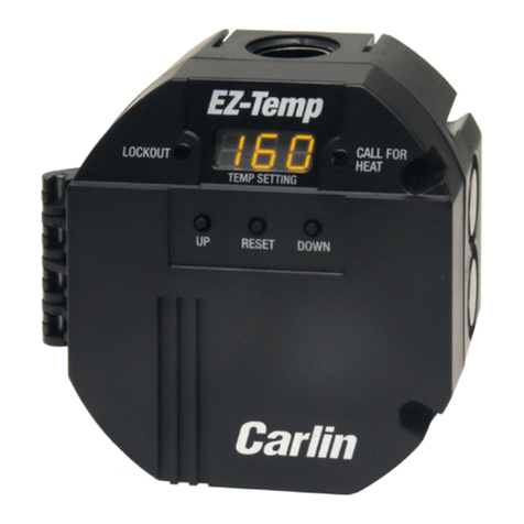
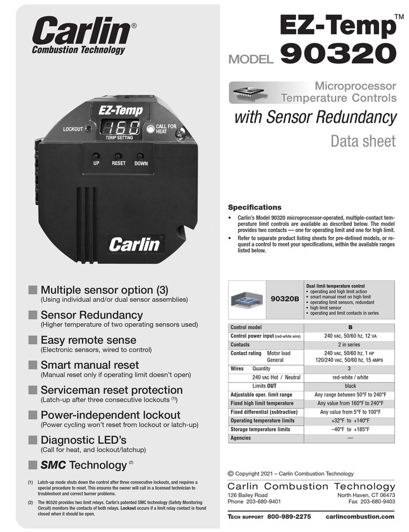
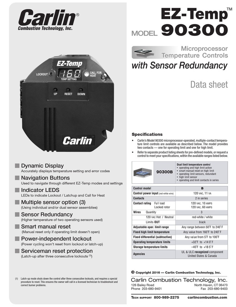
  9. Carlin EZ-Temp 90200 User manual

Carlin EZ-Temp 90200 User manual

Specifications
• Carlin’s Model 90200A and G microprocessor-operated temperature controls
are UL Recognized and provided as individual components with sensor and
well available separately.
• Carlin’s model 90200 microprocessor-operated temperature controls are
available in two configurations described below. Each model provides one
limit-duty-rated contact.
• Refer to separate product listing sheets for pre-defined models.
Data sheet
90200A
Temperature limit control
• 1 break-on-rise contact
• 1 electronic sensor
• lockout on diagnostic failure
• reset from lockout via power cycle
90200G
Temperature limit control
• 1 break-on-rise isolated contact
• 1 electronic sensor
• lockout on diagnostic failure
• reset from lockout via power cycle
Control modelA G
Control power input (red-white wire)120 VAC, 11 VA
Contacts
(action on temperature rise:)
3
(breaks)
4
(breaks)
Contact rating Full load
Locked rotor
120 VAC, 10 AMPS
120 VAC, 60 AMPS
Wires Quantity
120 VAC H& Limit IN / Nred-white / white
Break-on-rise OUTblack
black/
green
black
Adjustable oper. limit rangeAny range between 50°F to 240°F
Fixed differential (subtractive) Any value from 5°F to 100°F
Operating temperature limits +32°F to +140°F
Storage temperature limits –40°F to +185°F
Agencies UL & ULC Recognized
United States & Canada
126 Bailey Road North Haven, CT 06473
Phone 203-680-9401 Fax 203-680-9403
Carlin Combustion Technology, Inc.
Tech support 800-989-2275 carlincombustion.com
©Copyright 2016 — Carlin Combustion Technology, Inc.
mMicroprocessor-operated
(Processor coordinates limit and diagnostic functions)
mEasy remote sense
(Electronic sensor, wired to control)
mSelf-checking program
(Control locks out on diagnostic failure)
mDiagnostic/status LEDs
(LED’s indicate power, call for heat, and lockout)
MN90200A 090117
Model 90200A and G Microprocessor Temperature Controls — Data sheet
Electrical shock hazard: Disconnect power to appliance when wiring or servicing any electrical component.
Model 90200A and G
Diagnostic LED’s
Button Press Instructions
R A
R A
125
RA
125
R A
125
RA
E0 1
RA
E0 1
RA
E0 1
Power Off
Power On
No Call for Heat
Call for Heat
Lockout
Latchup, red flashes
every 2 seconds
Primary Relay
Warning, red flashes
every 5 seconds
Quickly press the UP or DOWN button to display temperature.
Press and hold UP and DOWN buttons for 5 seconds to enter
“Set Temperature” mode.
Press the UP or DOWN button to increase or decrease the “Set
Temperature”.
Do not press any buttons for 5 seconds to exit the “Set Tem-
perature” mode and save the new temperature.
Press and holde UP and DOWN buttons during power up to
enter “Diagnostic Mode” mode.
Press the DOWN button to move to the next error recorded in
the 16 deep error log. When you see an “E – –” displayed, you
have reached the end of the log. If you press the DOWN button
again, you will cycle back to the beginning of the log.
Press and hold RESET for 3 seconds to clear all recorded logs.
Press and hold RESET for 5 seconds to exit Lockout.
Press and hold RESET for 30 seconds to exit Latchup.
Display Mode
Set Temp Mode
Diagnostic Mode
Lockout Mode
Latchup Mode
Up Reset Down
Power, Off – (How to enter = No power is applied to the red-white wire)
• All lights and screen will be off.
Power, On – (How to enter = Power applied to red-white wire)
• System will power on and enter NORMAL OPERATION MODE
Call for Heat/High Fire – When the temperature at the operating sensor is
at or below setpoint minus fixed differential, the control powers the limit
relay.
Stand By/Low Fire – When operating sensor reaches setpoint temperature
or above, temp control will turn off the relay (break-on rise contact
opens).
Normal Operation (Mode) – (How to enter = Initial starting mode)
• The EZ-Temp will display the User Set Temperature.
Display – (How to enter = Pressing UP or DOWN key in NORMAL MODE)
• In DISPLAY MODE, the EZ-Temp will display current temperature read-
ing for 5 seconds, then return to NORMAL OPERATION
Setting – (How to enter = Hold up and down buttons for 3 seconds while in
NORMAL OPERATION)
• In SETTING MODE, the user is able to adjust the operating limit (via
setting the set temperature). Once in this mode, the display will begin
flashing the current set temperature. The display will increase one
degree per UP or DOWN button push or 10 degrees per second the
button is held.
Diagnostic – (How to enter = Power up the system with the UP and DOWN
buttons depressed. Once buttons are released, the system will move
into diagnostic mode)
• DIAGNOSTIC MODE displays recorded error codes. When powered in
this mode, the display will show the newest recorded error code. As
the DOWN key is pressed, the system will display error codes from
newest to the oldest. When there are no more codes to display, the
EZ-Temp will show a “—“ to indicate end of error codes. If the user
continues to push the down button, the system will go back to the
newest error code and begin displaying the error codes again from
newest to oldest. The only way to exit this mode is to power cycle the
system. To clear error codes (while in diagnostic mode), push and hold
RESET button for 3 seconds.
High Limit Test – (How to enter = In NORMAL OPERATION, hold RESET, UP
and DOWN buttons for 3 seconds)
• During this operation, EZ-Temp will display a flashing 180 (or your
current high temp). Pressing the DOWN button adjusts the high limit
temperature The high temp will decrease one degree for each press of
the DOWN button. If the DOWN button is not pressed for a period of 10
seconds, the unit will return to normal operation. When the high limit
is reached, the unit goes into hard lockout and displays the error code.
Lockup will follow. Holding the RESET for 3 seconds clears the lockout
and returns the high limit to default (180°). If the lockout condition has
driven the unit into latchup, the RESET must be held for 30 seconds.
Soft Lockout – (How to Enter = When any temperature sensor goes out of
range or the system has detected a high temp condition and the primary
and safety relays are still operational)
• When in this state, it will display the error code but will leave the
lockout LED off. If the condition that caused the soft lockout clears, the
system will return to normal operation.
Lockout – (How to Enter = Numerous Error Codes)
• The EZ-Temp will enter this state when an unsafe condition has oc-
curred and the user must intervene and put the system in a safe state.
Lockout can be cleared by pressing the RESET button for 3 seconds.
Latchup – (How to Enter = Occurs after 3 LOCKOUTs have been detected)
• The system will enter a safe mode and will not exit the mode without
user intervention. You can exit latchup mode by depressing the RESET
button for thirty seconds. By exiting this way, the system will reset the
lockout count back to zero.
Operation Modes
LEGEND
MN90200A 090117
Model 90200A and G Microprocessor Temperature Controls — Data sheet
Mounting – 90200A and G controls mount to any standard well.
Mount the 90200A & G directly to a well (new or existing) with
hardware supplied in the separate well mounting kit.
Well Kits – Wells for 90200A and G sensors are available in the
sizes shown below. Well kits include sensor mounting hard-
ware designed to hold sensor securely in position.
Sensors – Sensors are available separately for the 90200A and G.
Configurations
Error Codes
3"
43/8"
43/4"
Error Code Reason
01 Primary (K2) relay is welded on. Note: If the control is reset
from error code 01, the red LED will flash every 5 seconds
indicating the control must be replaced.
02 Primary & Safety relays (K1 and K2) on. The control cannot
be reset from error code 02 and must be replaced.
03
Primary & Safety relays (K1 and K2) are off. Note: If this
error is detected, the control will show error code 03 and
enter soft lockout two times to try and resolve the issue. If
the problem persists the control will enter hard lockout.
05 Simulated High Temp lockout
06 Temp is above set high temp but below thermistor high
(250°F)
Error Code Reason
20 Temp sensor 1 out of range failure
21 Temp sensor 2 out of range failure
22 High limit temp sensor out of range failure
23 Temp sensor 1 pin is open
24 Temp sensor 2 pin is open
25 High limit temp sensor is open
10,11,12,13,14,15 Internal hardware safety failure – unit should be replaced. Contact customer service for additional informa-
tion. 1-800-989-2275
H
G
Service
switch
90200A
Black
Red/White
White
Limit contact: Model A breaks on temperature rise
To sensor
Limit OUT
120
VAC
POWERTO
APPLIANCE
N
G
120
VAC
CONNECTIONS
AT APPLIANCE
Sensor
H
G
Service
switch
90200G
Red/White
White
Control contact — Breaks on temperature rise
To sensor
Low-fire control to burner
120
VAC
POWERTO
APPLIANCE
N
G
120
VAC
CONNECTIONS
AT APPLIANCE
Sensor
Black
Black/Green
Model 90200A and G Microprocessor Temperature Controls — Data sheet
MN90200A 090117

Other Carlin Control System manuals

Carlin EZ-Temp User manual

Carlin

Carlin EZ-Temp User manual

Carlin 60200 User manual

Carlin

Carlin 60200 User manual

Carlin 50200 User manual

Carlin

Carlin 50200 User manual

Carlin EZ-Temp 90320 User manual

Carlin

Carlin EZ-Temp 90320 User manual

Carlin EZ-Temp User manual

Carlin

Carlin EZ-Temp User manual

Carlin EZ-Temp 90300 User manual

Carlin

Carlin EZ-Temp 90300 User manual

Carlin 48245 User manual

Carlin

Carlin 48245 User manual

Carlin EZ-Temp 90000B User manual

Carlin

Carlin EZ-Temp 90000B User manual

Popular Control System manuals by other brands

CAME GARD series manual

CAME

CAME GARD series manual

HomeSeer PRO-100 S5 quick start guide

HomeSeer

HomeSeer PRO-100 S5 quick start guide

Bouyer PC-2112 manual

Bouyer

Bouyer PC-2112 manual

Genmitsu PROVerXL 6050 Plus user manual

Genmitsu

Genmitsu PROVerXL 6050 Plus user manual

BFT RANCH C 275/600CN Instructions for installation

BFT

BFT RANCH C 275/600CN Instructions for installation

Hach RTC105 user manual

Hach

Hach RTC105 user manual

ELIKA 460 installation manual

ELIKA

ELIKA 460 installation manual

Hydronix Hydro-Control HC07 installation guide

Hydronix

Hydronix Hydro-Control HC07 installation guide

DoorKing 2112 Installation & owner's manual

DoorKing

DoorKing 2112 Installation & owner's manual

Paso PA8500-VES Instructions for use

Paso

Paso PA8500-VES Instructions for use

Toshiba BMS-TP5121PWE owner's manual

Toshiba

Toshiba BMS-TP5121PWE owner's manual

Turnstiles Traffic H1 operating instructions

Turnstiles

Turnstiles Traffic H1 operating instructions

WELBA WTS-300 quick start

WELBA

WELBA WTS-300 quick start

Carel FLSTDMAHUE user manual

Carel

Carel FLSTDMAHUE user manual

K-Systems K1600 Installation, start-up, operation

K-Systems

K-Systems K1600 Installation, start-up, operation

Aimco AM-45 instruction manual

Aimco

Aimco AM-45 instruction manual

Fast RAVEN HAWKEYE Setup manual

Fast

Fast RAVEN HAWKEYE Setup manual

Madel FujiBox Guide

Madel

Madel FujiBox Guide

manuals.online logo
manuals.online logoBrands
  • About & Mission
  • Contact us
  • Privacy Policy
  • Terms and Conditions

Copyright 2025 Manuals.Online. All Rights Reserved.