CARLO GAVAZZI Dupline Carpark 3 User manual


Car Park 3 –Planning and design 2
Table of contents
List of abbreviations used in this manual.................................................................................................... 3
Introduction...................................................................................................................................................... 3
System description......................................................................................................................................... 4
Cabinet modules (DIN-rail mounted) ............................................................................................................ 4
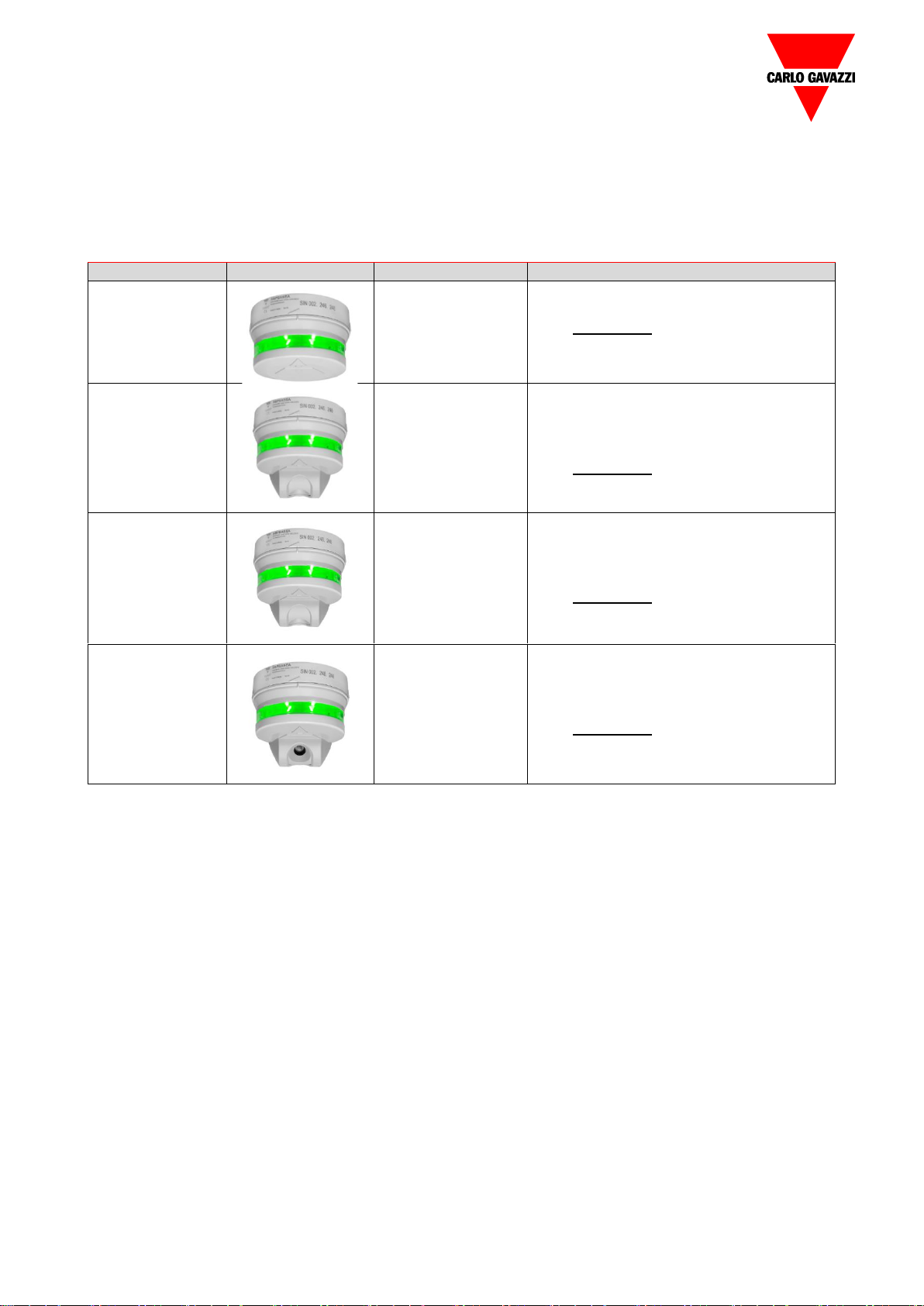
Sensors .......................................................................................................................................................... 5
Displays.......................................................................................................................................................... 6
Planning a Dupline®Parking Guidance System (PGS)............................................................................ 7
1. Gathering information about the parking system................................................................................. 9
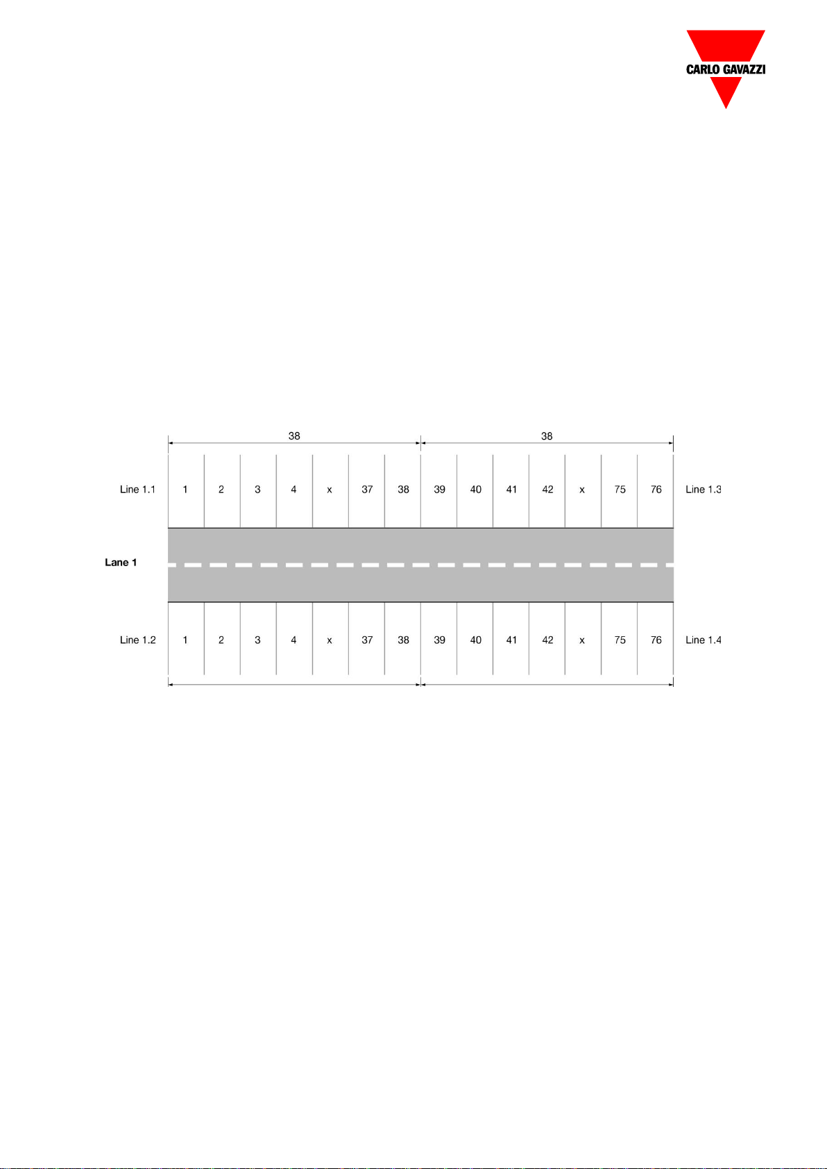
2. Lane, line and position......................................................................................................................... 10
Example ................................................................................................................................................... 10
3. Designing the placement of sensors, indicators, cable trays and cabinets......................................... 11
4. Addressing parking bays and displays ................................................................................................. 12
5. Designing the placement of the master channel generator ............................................................... 12
Rule of thumb.......................................................................................................................................... 12
6. Designing the placement of displays................................................................................................... 14
7. Designing the placement of cable trays and cabinets......................................................................... 14
Example 1: a one-floor system ................................................................................................................ 14
Example 2: a PGS for multiple floors....................................................................................................... 17
8. Combining lanes to a complete system............................................................................................... 19
9. UWP 3.0 platform for a complete system........................................................................................... 20
Further consideration................................................................................................................................... 20
Next Steps...................................................................................................................................................... 21
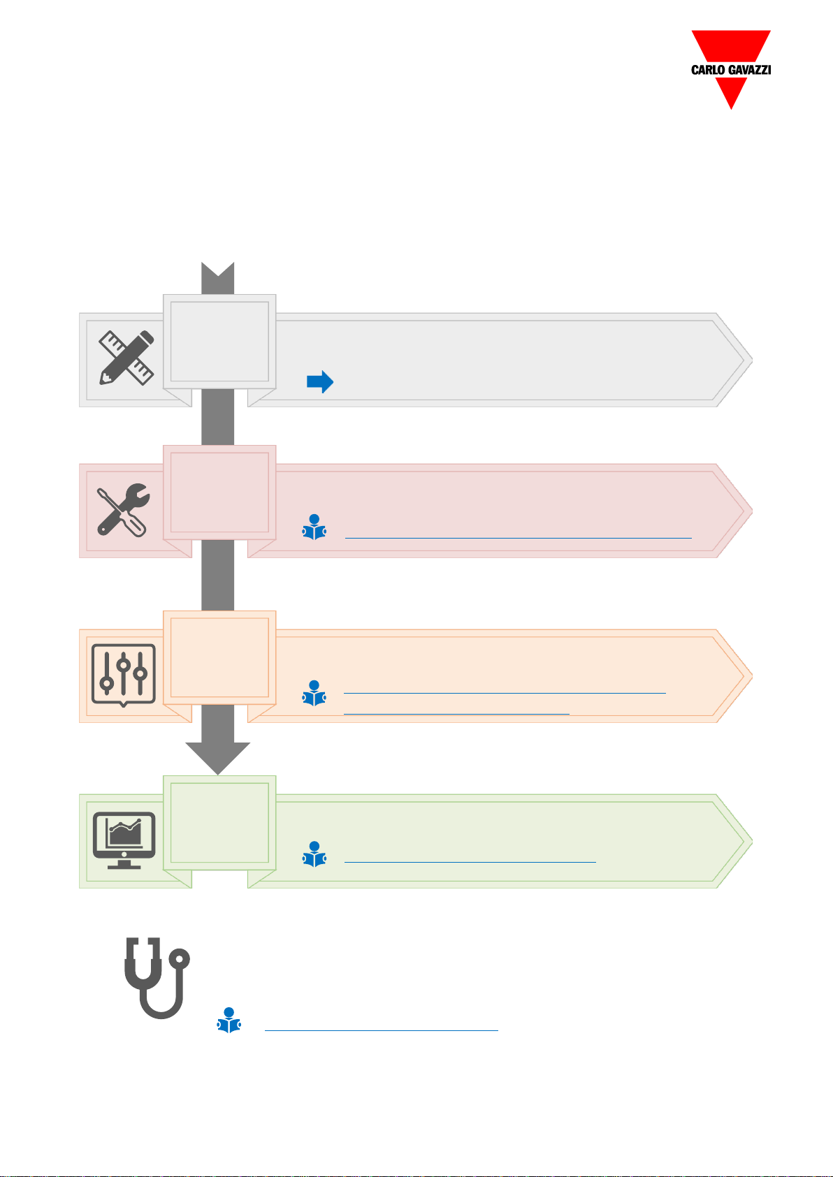
Installation and configuration ..................................................................................................................... 21
Software and Web server............................................................................................................................ 21

Car Park 3 –Planning and design 3
Carlo Gavazzi Carpark 3
List of abbreviations used in this manual
PGS –Parking Guiding System
CMCG –Carpark Master Channel Generator
CC –Carpark Controller
CS –Carpark Server
DIM –Display Interface Module
PCB –Printed Circuit Board
SIN - Specific Identification Number
MZC –Master Zone Counter
DPO –Detection Point
Introduction
The Dupline® 3 Parking Guidance system saves time and reduces the drivers’ stress.
Dynamic displays, strategically positioned throughout the facility, count the available bays and
efficiently guide the driver to the vacant bays through clear and bright green arrows.
If there are no vacant parking bays in an area, the display shows a bright red cross to discourage
the drivers from entering this area. Other displays can be positioned to show the total ammount of
vacant bays of a level or of the entire parking facility. Dynamic message displays can also be used
in the facility to provide drivers with additional information (such as Caution, Construction ahead,
Buckle-Up etcetera).

Car Park 3 –Planning and design 4
System description
This chapter provides an overview of the structure and a short description of the basic elements of
the parking guidance system.
Cabinet modules (DIN-rail mounted)
Type of
module
Photo
Part Number
Description
UWP 3.0
UWP30RSEXXX
Monitoring gateway and controller.
(See Datasheet)
Dupline®
Carpark
Display
Interface
SBP2DI48524
Display Interface Module for CP3 displays
(See Datasheet)
Dupline®
Carpark
Master
Generator
SBP2MCG324
•3-wire bus generator 28VDC
•Up to 90 CP3 sensors
•Up to 50 sensors on one line
(See Datasheet)
Dupline®
Carpark
Server
Module
SBP2CPY24
•CPY Server Module
•With built-in webserver
•Up to 10 UWP 3.0
•Up to 6300 spaces
(See Datasheet)

Car Park 3 –Planning and design 5
Sensors
Each parking bay belonging to a lane/line needs a sensor to detect a car. Each sensor must be
connected to a 3-wire carpark bus, assigned by the UWP 3.0 Tool, to transmit the sensor status
(occupied, vacant, disabled, VIP, etc.). The built-in LEDs will clearly indicate to the drivers if the
parking bay is available or not.
Type of module
Photo
Part Number
Description
Led indicator
SBPILED
CP3 LED Indicator for CP3 sensors
(See Datasheet)
Counter
SBPSUSCNT
•CP3 Count Sensor for counting cars
in a count system
•To be mounted in the driving lane
(See Datasheet)
Vertical sensor
SBPSUSL
•CP3 Vertical Sensor
•To be mounted directly over the car in
a parking space
(See Datasheet)
Lane Sensor
SBPSUSL45
•CP3 Lane Mounted Sensor
•To be mounted in the lane pointing
towards the parking space
(See Datasheet)

Car Park 3 –Planning and design 6
Displays
Displays show the number of available carpark bays and / or the direction. The display can be
mounted anywhere on the Dupline® bus and can be programmed to show whatever number of
available bays the installer decides: in total, lane by lane, bays for disabled, for VIP or a
combination of the different options together.
Type of module
Photo
Part Number
Description
Carpark Display
DISARSE
•Up to 4 digits or 1 symbol
•2 digits or 2 symbols
(See Datasheet)
DISBRSE
Up to 4 digits and 2 symbols
(See Datasheet)
DISCRSE
Up to 4 digits and 2 symbols
plus a running text
(See Datasheet)

Car Park 3 –Planning and design 7
Planning a Dupline®Parking Guidance System (PGS)
An old proverb says: ‘A good plan today is better than a perfect plan tomorrow.’ As in any good
system, the majority of your time and effort should be spent in the ‘planning’.
At first sight, you may think that the design of a Dupline® parking guidance system for a parking
facility with hundreds or thousands of parkingbays is a complex task. But as soon as you understand
the basic structure of the system, you will realise that it is simply composed of identically-structured
system lanes that linked together create a big system.

Car Park 3 –Planning and design 8
CarPark 3
Resources
PLANNING
AND
DESIGN
▪Defines the structure of the parking lot
▪Defines where the devices have to be placed
INSTALLATION
Wires pulling, rails installation, sensors, displays and cabinets
mounting
Link to the CP3 Installation manual (coming soon)
SYSTEM
CONFIGURATION
Configures and calibrate the Car Park 3 modules such as
sensors, indicators, displays
Defines where t device hasve to to be placed
Configures the CPY Server
CAR PARK
SERVER
CONFIGURATION
Link to the UWP 3.0 Tool configuration manual
Link to the DISxRSE user manual
Link to the CPY Server configuration
manual
The troubleshooting guide shows the most common issues and how to
solve them during the planning, commissioning and configuring
phases
Defines where the device hasve to to be placed
Link to the Troubleshooting guide
This Manual

Car Park 3 –Planning and design 9
1. Gathering information about the parking system
Acquire any technical drawings and layout of the parking system.
The drawings should:
•always be the latest version so to avoid any mistakes in the work.
•consist of lanes, cross-sections, parking bays (both regular and for disabled), location of
displays and cabinets, cabinet size, available power and the location of the equipment room
where the software server will be installed.
•indicate the traffic flow (single or bi-directional).
•be a true-to-scale CAD drawing with information of the parking structure, including the lane
distances so to determine the cabling and the maximum number of sensors allowed per
CMCG.
•describe parking bay dimensions (length, width and the distance from the floor to the ceiling).
The relationship between the floor and ceiling angle is also critical.
•indicate the dimensions from centre line to centre line of the bays.
•contain any information on using existing or new cable trays to pull wires for the sensors.
•define if an existing IP network can be used or you have to create a new TCP/IP network.
•determine the number of bays to be monitored on each level and in total.
•be JPEG, PNG or PDF to be imported into the CPY Server.

Car Park 3 –Planning and design 10
2. Lane, line and position
We use the terms Lane, Line, Position to refer to the logistics of the sensors in a carpark installation.
The Lane is the physical lane in a real parking lot. It can be a long or a short lane with a variable
number of sensors. This number depends completely on the structure of the building.
The Line is a technical term to refer to a string we use together with the lane. A lane can have
several lines with up to maximum 50 sensors. The lines can go in different directions from the
generator, like a star connection.
The Position is the placement of the sensors in each line.
Example
In the drawing below, there is a Lane (Lane1) with 76 bays on each side. The sensors of each line
are all named pos. 1, pos. 2 etc. Just like in the UWP 3.0 Tool, the sensors will be named 1, 1, 1 –
1, 1, 2 etc. Lane 1, Line 1 and position 1 and so on.

Car Park 3 –Planning and design 11
3. Designing the placement of sensors, indicators, cable trays and cabinets
1. After the definition of the LLP for each bay, choose among bay-mounted vertical sensors,
lane-mounted 45-degree sensors or sensors and separate LED indicators.
Note: If you want to use external LED indicator SBPILED, please make sure they are installed on
the lane, so that they are visible for drivers at a satisfactory distance.
2. The sensor/base can be mounted either on the ceiling or a rail. Daisy-chain all the sensor
bases and display interface modules in the lane with the Dupline® 3-wire bus.
3. Power the system ON
4. Set the sensors and displays up by means of the UWP 3.0 Tool.
5. Mount the sensor directly on the ceiling, in a tray or lowered.
Note: always try to choose the most functional and aesthetic solution according to cost-
effectiveness.
6. Select the bays to be used for the disabled parking bays.
Note: Normally, disabled parking bays are placed close to escalators and elevators, and their
numbers are determined in accordance with regulatory laws.

Car Park 3 –Planning and design 12
4. Addressing parking bays and displays
You can address the parking bays and the displays using the UWP 3.0 Tool.
Notes
•All the sensor bases have a unique SIN number. The SIN numbers do not need to be in
consecutive order, but their activation does.
•You can use the same sensor for different purposes (Normal, Disabled, VIP) one next to
the other: the difference is generated by the UWP 3.0 Tool.
5. Designing the placement of the master channel generator
It is very important to define the sensors mounting place for wiring them according to the master
channel generators position.
Rule of thumb
•A maximum of 50 sensors in a line
•A maximum of 90 sensors per generator
•A maximum of 150 m (490 feet) of wire in a line (branch)
Notes:
•The wire must be an unshielded 14-16 AWG type (1.5mm2).

Car Park 3 –Planning and design 13
•If the line has less than 50 sensors and the wire is longer than 150 m (490 feet), please refer to
the voltage drop calculation described in the CP3 Installation manual (Calculation).
For placing 50 sensors on a line and 90 sensors on a generator, the lane must be divided into four
equal parts, with 38 sensors in each part, and 4 lines for one lane.
Place two generators in the opposite ends of the Lane 1 and supply the Lines 1.1-1.2 and Lines
1.3-1.4, respectively. In total, each generator supplies 2*38=76 sensors.
The generators must be placed so to reduce unnecessary wire length: exceeding wire increases
the voltage drop thus reducing the number of sensors in the installation.
For further information, please refer to the section ‘Calculation’ (CP3 Installation manual).
The number of sensors determine the size of the power supply. For the pulsating output from the
CMCG, always use a double-size power supply with power-out on 28 V dc. When you use a 28 V
dc/2.5 A power supply, you can install 50 sensors on a line. When you use a 28 V dc / 5 Amp
power supply, you can install 90 sensors per generator (CMCG).

Car Park 3 –Planning and design 14
6. Designing the placement of displays
1. Define the number of displays based on the natural flow of cars in the parking facility, by
making a walk-through or drive-through with the customer.
2. Take any architectural considerations with the customer regarding signals, finding the
drivers’ way and any other equipment to be installed in the parking facility.
3. Split the parking into segments using the lanes.
4. Define the type of display content (arrow, red-cross, available bay counting) according to
the natural flow and to the customer’s requests or needs.
5. Determine the necessary environmental ratings of the displays according to the intended
use and installation.
Note: you should also take into consideration the accidental water ingress from plumbing
leaks and wind-blown rain or snow.
6. Decide if there should be one or more multi-level ‘Tower’or ‘Totem’ displays installed at the
entrance of the parking, providing a snapshot of all the available bays on each level.
What should the displays show?
Several available bays in many lanes or just local available bays of a single lane.
Each display is connected to a display interface, which also has a SIN number. The display
interface is connected to the same Dupline® bus as the Carpark sensors. The display can be
placed anywhere on the Dupline® bus and on any CMCG in the system. The data to be shown on
the display are available on any Dupline® bus of the entire Carpark system.
7. Designing the placement of cable trays and cabinets
1. Determine the number and placement of the cabinets.
Notes:
•The cabinets should be placed so that the sensor loads are equal in all directions.
•They should be accessible only by ladder or cherry picker so as to be protected
from tampering.
•The maximum rating of the enclosures should be NEMA 3R or IP54.
2. Use aesthetic cable rails, where sensors can be installed and cables can be pulled and
mounted.
3. Place cabinets in a logical way with short distances to the lanes to avoid long cables.
For example, place many small cabinets in the area or on the floor or place a big cabinet in
the middle of the area or floor.
Example 1: a one-floor system
The diagram below is a example of how to implement 477 sensors on a single floor. Additional
floors would be configured, installed and brought online in the same way. Refer to section ‘Example
2: a PGS for multiple floors’.

Car Park 3 –Planning and design 15
In the planning process, the displays are positioned at the entrance and at each line.
The entrance display (A) shows all the available bays of the entire floor. The first branch display
(B) shows the available bays on that particular lane. The displays (C) and (D) also show the
available bays from their lanes.
In this example, we do not have a display showing the available bays for disabled people.
However, it would be easy to add a separate display to the software, and we would recommend to
order some extra Carlo Gavazzi modules:
•one display
•one display interface (SBP2DI48524)
•one power supply as hardware for this extra feature.
If, for instance, 20 bays are designated as bays for disabled people, we have to point out these
bays in the configuration software to make them visible on the display.
Designing the lanes can be made in many ways. We always suggest an easy structure with a good
overview, which holds an extra margin for voltage drop, power consumption and any future
installation.
In the example shown ”above”, we have 6 lanes. Lanes 1, 2, 3, 4 and 5each have two lines with
45 bays per line, totalling 90 sensors per lane. Lane 6 has one line with 27 bays.
The cable length calculated is 135 m (435 feet), so there is a margin for both voltage drop and
power consumption calculations.

Car Park 3 –Planning and design 16
You should mount the three cabinets C1, C2 and C3 as shown in the scheme above. If it is not
possible, you should find an alternative placement.
Note: the distance between the cabinet and the last sensor on a line has not to exceed a
voltage drop of 3.5 V.
1. C1 should contain power supplies for Lanes 1, 2:
•Power supplies for Displays A and B
•Dupline® Master Generator SBP2MCG324 for Lanes 1 and 2
•The UWP 3.0 controller and/or the SBP2CPY24 Server (if more than one UWP 3.0
contoller is used)
2. C2 should contain modules for lanes 3 and 6
3. C3 should contain modules for lanes 4 and 5
4. Additional floors would be managed in the same way
5. The cabinets have to be placed closed to the B, C and D displays, providing us with the
shortest practical distance between the lanes.

Car Park 3 –Planning and design 17
Example 2: a PGS for multiple floors
Planning a Parking Guidance System (PGS) with multiple floors implies the same considerations
for planning one floor only.
Determine displays, lanes, natural car flow in the Parking Guidance System and, of course, all the
other phases in the process mentioned at the beginning of this installation manual.
Consider the cable lengths of the 3-wire Dupline® bus to supply sensors, displays and Ethernet
runs.
Refer to the following table describing the picture
Area
Description
Total bays
Ground
4 normal lanes (lanes) with 76 bays each
and including 4 bays for disabled people on
each of the 4 lanes.
16 disabled bays in total
304
Level 1
4 normal lanes (lanes) with 72 bays each.
288
Level 2
4 normal lanes (lanes) with 72 bays each.
Including 4 bays with disabled bays on each
of the 4 lanes.
16 disabled bays in total
288
A total of 880 bays, including 32 bays for disabled people.
All the lanes, including the disabled bays, are connected through a 3-wire Dupline® bus to the
selected SBP2MCG324 with a unique ID number.
Outside the PGS installation, three displays (Monument) show the number of the available bays on
all the three levels and two displays show the available disabled parking bays on the ground floor
and level 2.
The three displays that show the available bays on all the ‘normal’lanes (lanes) are connected to
any 3-wire Dupline® bus via a display interface module.

Car Park 3 –Planning and design 18
The two displays showing the available bays on all the disabled parking bays are connected to any
3-wire Dupline® bus via a display interface module.
In this example, we have 12 lanes so we need 12 SBP2MCG324s, one for each lane.
Note: It is possible to manage the system with fewer SBP2MCG324s, but to keep the installation
easy and logical, we use one SBP2MCG324 for each lane.
Having 12 SBP2MCG324s, we need two UWP 3.0 controllers and one SBP2CPY24 server.
Every SBP2MCG324 has a unique SIN number and it is connected to its local Car Park controller
(UWP 3.0).
Afterwards, the two UWP 3.0s are connected to the CPY Server (SBP2CPY24) to send the data to
the UWP 3.0 controllers.
The best installations have a well-thought-out layout as too many displays may become
counterproductive due to information overload.
On the level 2, we could have a display at the entrance that shows only the available bays of this
level.
Note: The disabled parking bays are not included.
A simple display (L31) showing a green arrow or a red cross is placed at the entrance of the level
2.
On each lane, we place a simple display with an arrow/a red cross to show available bays in that
direction.

Car Park 3 –Planning and design 19
8. Combining lanes to a complete system
When the lanes are defined, we use the UWP 3.0 controller and the SBP2CPY24 CPY server to
combine and upscale the Carpark system up to 6300 bays.
Each UWP 3.0 can operate with maximum 7 SBP2MCG324s (i.e. 7*90=630 bays in total).
By using the SBP2CPY24 CPY server, we can operate with ten SBP2WEB24s (i.e. 10*630
sensors, that is 6300 bays in total).
All SBP2MCG324s have a unique ID number (SIN number). Information on available and occupied
bays from the parking area are transmitted via the SBP2MCG324 to the UWP 3.0 controller and
then to the software. In carpark installations with less than 630 bays (maximum 1 UWP3.0), the
CPY Server is integrated into the UWP 3.0. In installations with mote than 630 bays (up to 10 UWP
3.0 controllers), a dedicated SBP2CPY24 is required.
Note: if additional bays are needed, please contact Carlo Gavazzi for further information.

Car Park 3 –Planning and design 20
9. UWP 3.0 platform for a complete system
You can easily build different kinds of building automation components like the CO sensor, light
sensors or movement sensors into a Parking Guidance System (PGS) system. By selecting the
UWP 3.0 controller, the customer will have flexible solutions at a lower cost.
Further consideration
It is also important to consider the installation costs, especially the necessary man-hours, but also
the costs of cables and wall boxes.
We recommend the use of inexpensive standard 3-wire, unshielded 1.5 mm2(14-16AWG) cables
for the Carlo Gavazzi Dupline® Parking Guidance System. In order to reduce man-hours for the
installation, we have designed the sensor in such a way that it can be wired easily and quickly without
the use of screwdrivers. The bases/sensors are programmed from the UWP 3.0 Tool when they are
mounted, wired and powered. The programming and calibration take just a few minutes to complete
a lane. Just make sure that no cars are occupying the carpark bays during the calibration.
Table of contents
Other CARLO GAVAZZI Automobile Electronic manuals
Popular Automobile Electronic manuals by other brands

TomTom
TomTom R-Link 300 299 installation manual

BMW
BMW 66 20 0 146 507 installation instructions

Alpine
Alpine DPR-RDS1 owner's manual

Westfalia Automotive
Westfalia Automotive Autocode-Mini Original operating instructions

Streamax
Streamax A5-E0804 MDVR user manual

Saab
Saab 12 787 887 installation instructions

APEXi
APEXi Auto Timer installation manual

Blaupunkt
Blaupunkt OSLO 370 DAB operating instructions

Volvo
Volvo 31399352 installation instructions

Rear view safety
Rear view safety RVS-115 user manual

Torqeedo
Torqeedo Cruise 10 FP TorqLink Translation of the original operating instructions

Right Weigh
Right Weigh 224-SK installation manual