iPark IPTSR400 User manual

IPTSR400
PARKING ASSIST SYSTEM MANUAL

ABLE OF CON EN S
1 Important Notice - Disclaimer - About The Product
2 ey Features - Technical Specifications
3 Self-Test Function - Learning Function
4 Attention – Sensor Maintenance - Audible Buzzer Function
5 Packing List - Installation Tools
6,7 Sensor Installation
8 Wiring Diagram
9 ECU Installation
10 Troubleshooting
11 Function Test After Installation
12 Buzzer Installation - Display Installation (Optional)

page 1
IMPOR AN NO ICE
iPAR ® Parking Assist Systems help to
provide assistance when reversing and
parking.
Driving skills, such as using caution,
slowing down, use of mirrors etc. are
always essential.
1. This unit is for use with 12V DC only.
2. Unit should be installed by a
professional auto technician to avoid the
warranty being voided.
3. Route wiring harness away from heat
sources and electrical components.
4. It is strongly recommended to check
behind the planned location of the
sensors before drilling.
5. Perform a test after installation is
complete.
DISCLAIMER
The parking assist system is designed as
a driver assistance device, and should not
be used as a substitute for safe parking
practices. The area into which the vehicle
is to be reversed must be constantly visu-
ally monitored while parking. The manu-
facturer, its distributors and sales agents,
do not guarantee against or assume
liability for collisions or damages while
reversing your vehicle.
ABOU HE PRODUC
This Parking Assist System is an
ultrasonic detection and distance
monitoring system.
It electronically detects the area behind
your vehicle while reversing, and alerts
you with audible tones that quicken and
eventually become a constant tone, if the
system detects an obstacle. If the system
has the optional display, it will show the
distance in FEET, numerically. This is, as
well as, audible tones and progressive
LEDs.
Each part of this product has passed a
stringent test during manufacturing. The
product is designed to operate at a wide
range of temperatures from -40ºF to
+175ºF and becomes very useful when
parking during poor weather conditions.
With the help of a Parking Assist System,
you can enjoy a comfortable and conven-
ient parking experience.

KEY FEA URES
• Buzzer can be upgraded to various displays (optional),
with built-in audible and display options
• System can be used as a 2 sensor system if desired
• Precise detection range
• Self-Test and Auto Anti-Falsing Alert technology
ECHNICAL SPECIFICA IONS
• Rated Voltage: . . . . . . . . . .12V DC
• Power Consumption: . . . .3.6W
• Working Temperature: . .-20ºC to +70ºC
• Detecting Distance: . . . . .1ft to 6.5ft
• Detecting Angle: . . . . . . .H>60º, V>60º
page 2

SELF ES FUNC ION
When reverse gear is selected, the sys-
tem will test the rear sensors
automatically.
If all sensors are working correctly, the
unit will beep once.
If a damaged or defective sensor is
detected the unit will beep three times.
Other sensors will continue to function
normally.
LEARNING FUNC ION
o set the unit. Turn ignition ON, shift
the gear from N to R and back for 10
times quickly in 1 second intervals (10
second total), ending with the gear lever
in Reverse.
Leave in R position for 6 seconds to
achieve “LEARNING” function.
o clear the memory. Turn ignition
ON, shift the gear from N to R and back
12 times quickly in 1 second intervals
(12 second total), ending with the gear
lever in Reverse.
Leave in R position for 8 seconds to
achieve “CLEAR” function.
NO E: If you forget or shift incorrectly,
please stay at R position for 2 seconds to
reset and the unit will assume that the
next time will be the first time..
page 3

-
A EN ION
False detection may occur in the
following situations.
• Angled or sloped walls or objects may
deflect the ultrasonic signal.
• Soft fabrics, carpeting or padded sur-
faces may absorb the ultrasound and
not give an accurate reading.
• Buildings with staggered walls or
insets may also absorb or deflect the
signal.
• Heavy Rain, dirty or damaged sensors
may also cause false warnings.
SENSOR MAIN ENANCE
Do not wash the sensors with a
pressure washer or scrub them forcibly.
Avoid wax or grim buildup in the
sensors. Wash the sensors with water in
a low pressure manner.
Please allow the ice to melt by
applying water when sensors are
covered with frozen ice.
AUDIBLE BUZZER FUNC ION
6.5FT to 4FT – Slow BEEP—BEEP—BEEP
4FT to 2FT – Faster BEEP BEEP
2FT to 0FT – Constant BEEEEEEP
page 4

PACKING LIS
4 Sensors . . . . . . . . . . . . . . . . . . . . . . . . . . . 1 Control ECU Module
4 Sensor Extension Cables . . . . . . . . . . 1 Audible BUZZER
1 Power Harness . . . . . . . . . . . . . . . . . . . . 1 Hole Saw
1 Square Two-Faced Mounting Tape . 1 Manual
INS ALLA ION OOLS
Power Drill . . . . . . . . . . . . . . . . . . . . . . . . . . Tape Measure
Electrical Tape. . . . . . . . . . . . . . . . . . . . . . . Scissors
Soldering Iron / Solder . . . . . . . . . . . . . . Hole File
Screw Driver . . . . . . . . . . . . . . . . . . . . . . . . Skill nife
(Approximately 30 to 60 Minutes)
page 5
IMPOR AN –The installation m st be completed o tdoors, 10 FEET clearance of any objects or b ildings etc.
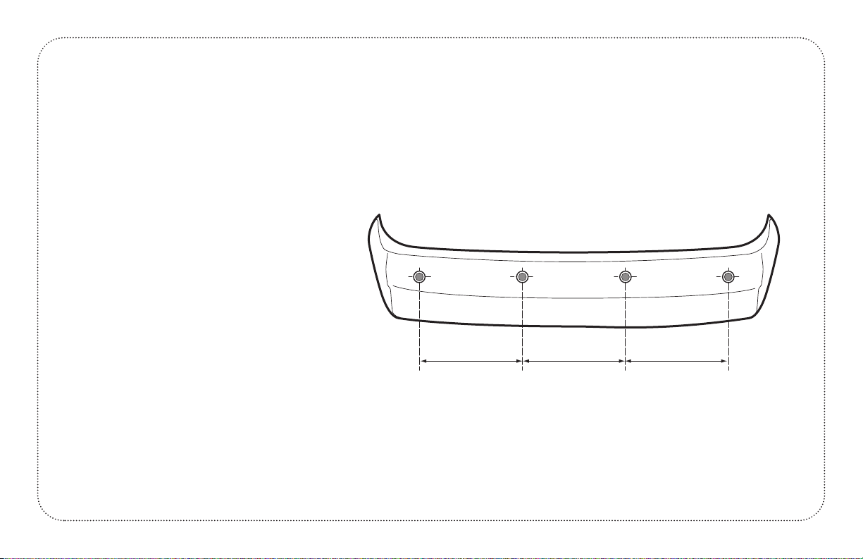
SENSOR INS ALLA ION
Please adjust the sensors angle to be
parallel to the ground surface
depending on the height and angle of
the mounting surface. Ideal mounting
height is between 18 to 25 inches.
Position the 4 sensors to be equally
spaced apart on the bumper. Best
location is outer two sensors spaced 8 to
10 inches in from outer edge of vehicle.
Measure the distance between the two
sensors, and divide by three to be
location for the other two sensors.
page 6
SENSOR INS ALLA ION
WHEN BUMPER IS REMOVED

A
C
BBA
TAPE
SENSOR INS ALLA ION (Continued)
DIREC ON VEHICLE BUMPER
page 7

MAIN BOX
RED +12V
BLACK GND
SENSOR A
4 SENSORS - INSTALL ON REAR BUMPERS
BUZZER
SENSOR B
SENSOR C
SENSOR D
REVERSE
LIGHT
WIRING DIAGRAM
Accessory (+)12V DC
Foot Brake (+)12V DC
Buzzer (-) Ground
Sensors E F G H
Wiring Diagram for 4 Sensor Front System
page 8
Table of contents


