8
Carlo Gavazzi Controls S.p.A.
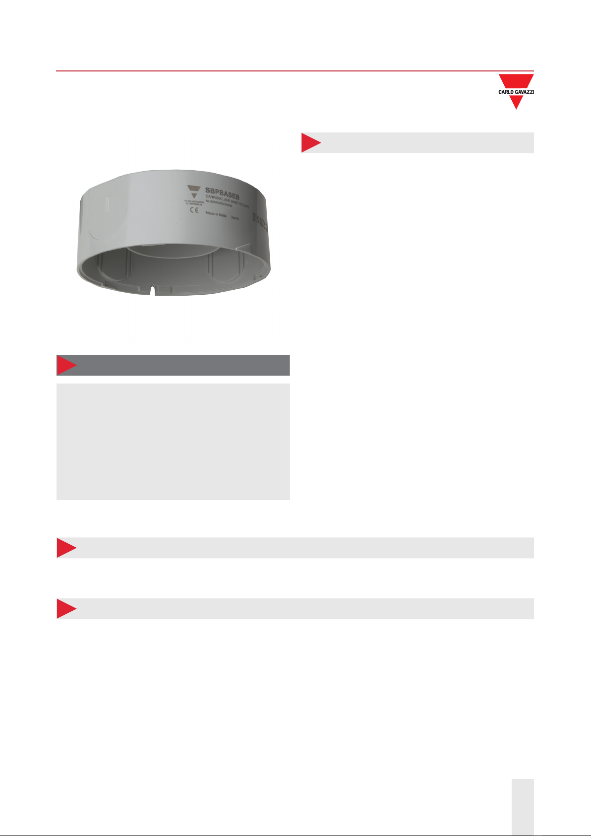
SBPBASEB
SBPBASEB ENG20/03/2019
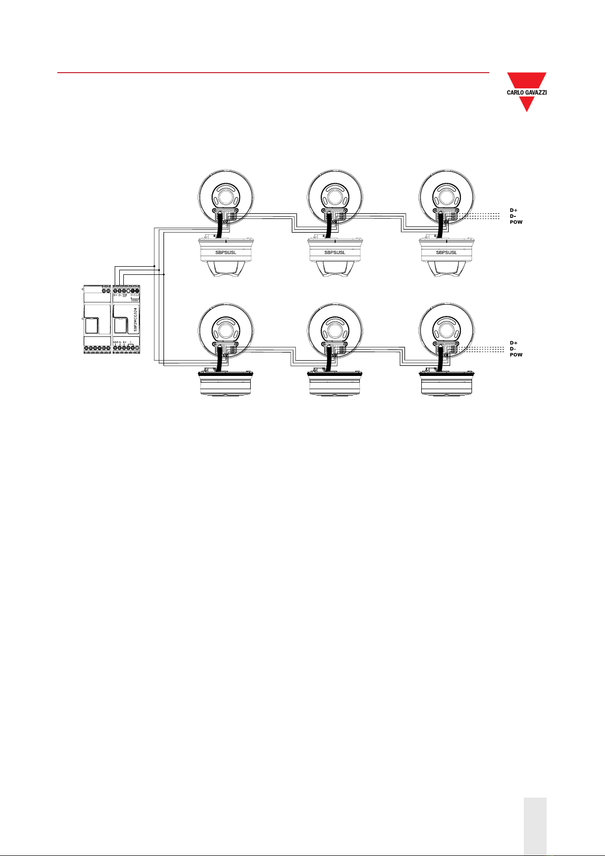
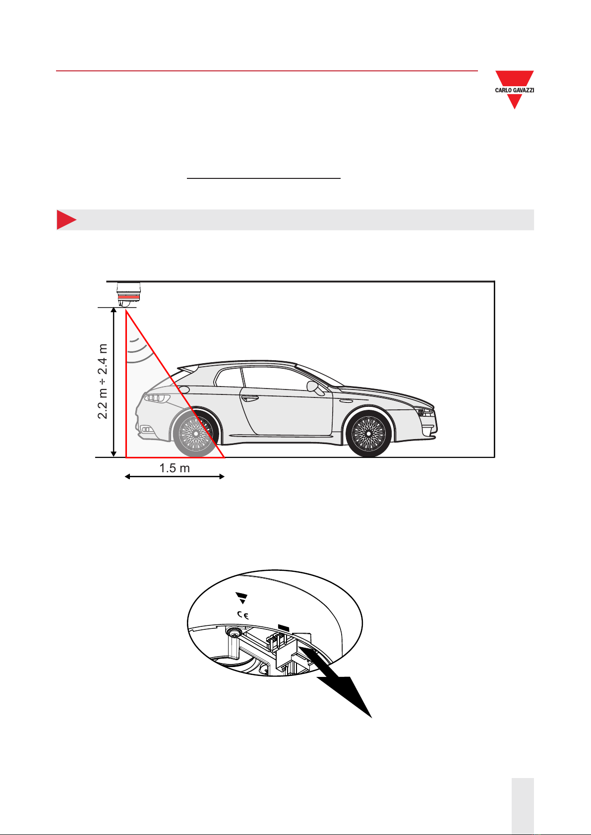
Installation of the SBPBASEB together with the SBPSUSCNT
The SBPBASEB together with the SBPSUSCNT sensors should be mounted in the driving lane at a height
between 2.0 to 2.5 m.
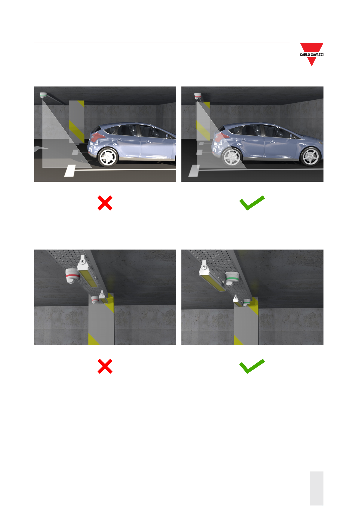
For each detection point the system permits the usage of one sensor or multiple sensors. In order to avoid
crosstalk and false detections two sensors should be used.
In this way, the system is also able to detect the direction of the cars.
Example 4
Please refer to the following table to place the two SBPBASEB bases together with the sensors at the proper
distance.
Sensor
height
(m)
Min.
distance
(m)
2.5 0.91
2.4 0.88
2.3 0.84
2.2 0.80
2.1 0.77
2.0 0.73
Fig. 3 Sensor height Tab. 1 Minimum distance
between sensors
Example 5
Should the driving lane be larger than the standard (2.5 to 3.25 m), please refer to table 2 to place the two
SBPBASEB bases together with the sensors at the proper distance:
Sensor
height
(m)
Max.
distance
(m)
2.5 2.53
2.4 2.45
2.3 2.38
2.2 2.31
2.1 2.23
2.0 2.16
Fig. 4 Sensor height Tab. 2 Maximum distance
between sensors