CARLO GAVAZZI Dupline User manual

Dupline®
Parking Guidance System
Design and Installation Guide

Contents
Introduction �������������������������������������������������������������������������������������������������������������������������������������������4
Planning a Dupline®Parking Guidance System ���������������������������������������������������������������������������������5
Phase 1: Gather Tools and Information ��������������������������������������������������������������������������������������������������������5
Phase 2: Display Placement, Segment Definition, Sensor Mounting ����������������������������������������������������������6
Phase 3: Design One Segment (…and Build From There) ���������������������������������������������������������������������������7
Phase 4: Linking the Segments to the L2 Bus ���������������������������������������������������������������������������������������������8
Phase 5: Dupline®Parking Guidance Software �������������������������������������������������������������������������������������������9
Secondary Considerations ����������������������������������������������������������������������������������������������������������������������������9
One-Floor System Example 9
Addressing Standard and Handicap Spaces 11
Example of a PGS for Multiple Floors 12
Master Zone Counter “MZC” ������������������������������������������������������������������������������������������������������������14
Introduction �������������������������������������������������������������������������������������������������������������������������������������������������14
Hardware �����������������������������������������������������������������������������������������������������������������������������������������������������14
Carpark Counter Module (GP32950030700) ���������������������������������������������������������������������������������������������14
Carpark Master Channel Generator (GP32900003700) �����������������������������������������������������������������������������15
HS BUS for all module types ����������������������������������������������������������������������������������������������������������������������16
Operating principles of the MZC �����������������������������������������������������������������������������������������������������������������17
Zones ����������������������������������������������������������������������������������������������������������������������������������������������������������17
Detection Points (DPO) �������������������������������������������������������������������������������������������������������������������������������17
Initialization and adjustment �����������������������������������������������������������������������������������������������������������������������17
MZC combined with Single Spot Detection �������������������������������������������������������������������������������������21
Zone counting system with split between standard and reserved spaces �������������������������������������������������23
Installation of the Standard Spot Detection System �����������������������������������������������������������������������24
Short Installation �����������������������������������������������������������������������������������������������������������������������������������������24
Sensors 24
LED Indicators 24
Car Park Monitor (CPM) Modules 24
Dupline®Master Modules 25
Cabling 25
Cabinets 25
Programming ����������������������������������������������������������������������������������������������������������������������������������������������25
2-Coloured Sensor 25
3-Coloured Sensor 26
CPM Modules 26
The Dupline®Fieldbus ������������������������������������������������������������������������������������������������������������������������26
General Information on the Fieldbus �����������������������������������������������������������������������������������������������������������26
Dupline®Bus Features 27
Dupline®Basic Elements 27
Dupline®Bus Including a 3’rd wire 27
Dupline®Extra Features 28

System Description ���������������������������������������������������������������������������������������������������������������������������28
Basic Modules ������������������������������������������������������������������������������������������������������������������������������������������28
Parking Guidance System Sensors 28
Indicator Lights 29
Master / Slave CPM 30
Parking Guidance System Displays 30
Dupline®Master Module (DMM) 31
Test and Configuration Unit 31
Optional Units 32
System structure ������������������������������������������������������������������������������������������������������������������������������32
Definition of a 1-Segment System ��������������������������������������������������������������������������������������������������������������32
The Dupline®master Module with DC Power Supply 33
Sensors and Indicators 33
Car Park Monitor(s) (CPM) with Display(s) 33
Segments Linked Together via L2 Bus for Totalizing 34
Software Network Added ������������������������������������������������������������������������������������������������������������������35
System requirements ����������������������������������������������������������������������������������������������������������������������������������37
Carpark
37
Carpark Server 37
Parking Guidance System Modules and Modes Explanation ��������������������������������������������������������37
Sensor Calibration ���������������������������������������������������������������������������������������������������������������������������������������37
Sensor Modes ���������������������������������������������������������������������������������������������������������������������������������������������38
Car Park Monitor Modes �����������������������������������������������������������������������������������������������������������������������������40
Slave Mode 40
Roof Mode 40
Master Mode 40
Master Indicator Mode 40
General Installation ����������������������������������������������������������������������������������������������������������������������������40
Cable ����������������������������������������������������������������������������������������������������������������������������������������������������40
Practical Cabling Techniques ����������������������������������������������������������������������������������������������������������������������41
Placing the Sensor ��������������������������������������������������������������������������������������������������������������������������������������41
Programming the Sensor ����������������������������������������������������������������������������������������������������������������������������44
Wiring the Sensor ����������������������������������������������������������������������������������������������������������������������������������������46
Programming the CPM Module ������������������������������������������������������������������������������������������������������������������48
Slave Mode 48
Master Mode 50
Cabinet Wiring ������������������������������������������������������������������������������������������������������������������������������������52
Simple Stand-alone Wiring �������������������������������������������������������������������������������������������������������������������������53
Extended Wiring for Parking Guidance System Software Solution ������������������������������������������������������������54
System Calculation ����������������������������������������������������������������������������������������������������������������������������55
Test and Troubleshooting of the System ������������������������������������������������������������������������������������������58
Tips ������������������������������������������������������������������������������������������������������������������������������������������������������59
List of Abbreviations Used in this Manual ����������������������������������������������������������������������������������������59

4
© Carlo Gavazzi A/S
List of Abbreviations Used in this Manual
Abbreviation Key Part number
MZC Master Zone Counter 1 x GP3295 0030 700
2 x GP32900003700
DMM Dupline®Master Module GP34960005700
CPM Carpark Monitor GP34829091724
DPO Detection point
PGS Parking Guidance System
List of illustrations
Fig� 1: Example of a basic facility 7
Fig� 2: Example of a Parking Level with Phase 2 Considerations: 9
Fig� 3: Example of approved/not approved cable length 10
Fig� 4: CPM modules connected to bus L2 11
Fig� 5: Placing the cabinets 13
Fig� 6 : Example of a PGS with multiples floors 15
Fig� 7: Master Zone Counter (MZC) 16
Fig� 8: GP32950030700 17
Fig� 9 : GP32900003700 - LEDs 18
Fig� 10 : Internal or external HS Bus connection 18
Fig� 11: A simple parking facility with one entrance and one exit 20
Fig�12: Connection diagram for the simple stand-alone system 21
Fig�13: Carpark with multiple entrances and exits 21
Fig� 14: Parking facility with multiple zones and multiple exits 22
Fig� 15: Connection diagram for 2-zone 4-DPO example 23
Fig� 16: Single spot detection and count system combined 24
Fig� 17: Example of a basic Dupline®system 29
Fig� 18: Sensors with built-in LEDs 30
Fig� 19: Driveway with external indicator lights providing a clear view 31
Fig� 20 : Car Park Monitor - GP 3482 9091 724 32
Fig� 22: Dupline®Master Module (DMM) for parking systems - GP34960005700 33
Fig� 23 : Parking guidance test and configuration unit - GP 7380 0080 709 33
Fig� 21 : Display 33
Fig� 24 : One-segment system 34
Fig� 25: LED indicators powered by bus or sensor 36
Fig� 26: Three segments connected to Bus L2 37
Fig� 27: Parking Guidance System overview 38
Fig� 28: Calibration of a sensor (local) 40
Fig� 29: Global calibration of sensors 40
Fig� 30: Vacant/occupied signaling 41
Fig� 31: Global/local display 41
Fig� 32: 3 * 1,5 mm2multi core wire with ferrule 43

5
© Carlo Gavazzi A/S
Fig� 33: 3 * 1,5 mm2(14-16AWG) single core wire 43
Fig� 34: Placing the sensor 44
Fig� 35: Sensors mounted on cable tray 44
Fig� 36: Sensors mounted on ceiling 45
Fig� 37: Lowered sensor installation 45
Fig� 38: Installing a ceiling sensor 45
Fig� 39: Mounting in a parking space 46
Fig� 40: Sensor and programmer GP7380 0080 46
Fig� 41 47
Fig� 42 47
Fig� 43 47
Fig� 44 48
Fig� 45 48
Fig� 46 49
Fig� 47 49
Fig� 48 49
Fig� 49 50
Fig� 50: Configuration of master/slave 50
Fig� 51: Device ID for slave mode 51
Fig� 52:� Mode selection for slave mode 51
Fig� 53: Calibration in slave mode 51
Fig� 54: Lane detection in slave mode 51
Fig� 55: Off Delay Lane in slave mode 51
Fig� 56: Select/See channel for each connected sensor in slave mode 52
Fig� 57: Offset spaces in slave mode 52
Fig� 58: Roof Spaces in slave mode 52
Fig� 59: In/Out channels and Reset channels in slave mode 52
Fig� 60: Selection between master and slave mode 53
Fig� 61: Indicator in master mode 53
Fig� 62: System size in master mode 53
Fig� 63: ID number in master mode 53
Fig� 64: Offset spaces in master mode 54
Fig� 65� Send data to unit (both sensor and master/slave unit) 54
Fig� 66� Message from the Configuration unit 54
Fig� 67: Extended Carpark Wiring with Cabinet 55
Fig� 68: Simple guidance system with two CPM slaves 56
Fig� 69: Wiring 56
Fig� 70: Extended wiring 57

6
© Carlo Gavazzi A/S
Introduction
The Dupline®Parking Guidance system saves time and reduces stress for drivers�
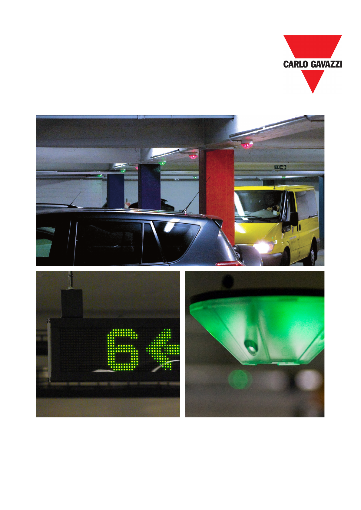
Dynamic displays strategically positioned throughout the facility provide “space available” counts and
efficiently guide the driver to open spaces with clear and bright green arrows pointing the way�
If there are no open parking spaces in an area, the sign will display a bright red cross to discourage
the drivers from entering this area� Other displays can be made to display the total number of open
spaces on a particular level or in the entire parking facility� Dynamic message displays can also be
used in the facility to provide additional information to drivers� Some examples could be Caution;
Construction Ahead; Buckle-Up, and any other message that needs to be communicated to the driv-
ers in the facility�
In the parking space
Each parking space is equipped with a clear indicator light, which is green when the space is open
and red when it is occupied� If the space is for handicap parking, the colors become blue and red� The
bright LED indicators provide a visual reference as drivers seek out open parking from a distance� The
indicator lights are combined with an ultrasonic sensor as a complete set�
The Dupline®Parking sensors utilize a special ultrasonic frequency, much like a bat uses to search
for flying insects� A sophisticated microprocessor contained in the sensor knows how much time that
it should take for a sound wave to “bounce” from the floor back to the sensor� If a vehicle is parked
in the space, this time is measurably shortened and the logic in the microprocessor determines that
a vehicle is present in the space� Once detection has been confirmed, the indicator lights will switch
from green or blue to red and the displays and the software counts will be accurately updated as well�
Master Zone Counter “MZC”
This installation manual does not describe the MZC in details� The MZC has its own installation man-
ual which describes in details the programming of the MZC, programming and installation of the sen-
sors, using the configuration unit, installation examples and a lot more� This manual informs about the
overall features of the MZC and in which Carpark installations it can be used� Moreover, it will describe
how to combine spot detection and counting�
The Software…
The Dupline®Parking Guidance System is inherently robust and a stand-alone system� This system
does not require a PC to run� However, optional software makes it possible to monitor the real-time
situation of each parking space or level in a facility� It also has a full alarm component that can provide
logging and indication of a variety of conditions exceeding user-defined limits�
Some typical alarm functions include time-limits for individual spaces, occupied levels, and maximum
occupied indications� Additionally, the software graphically displays tables and graphs showing the
occupancy rates for the areas, the floors and the entire facility�
The software is also a tremendous tool for data logging and historical trending and analysis� Data can
be stored and utilized for multiple facilities, a single facility, a level, or even to an individual space�
The software allows authorized operators to book or reserve spaces� When an open space is booked,
the associated indicator light in the parking space will turn red and it will provide a connection to the
software's overview where the corresponding virtual indicator light turns red�

7
© Carlo Gavazzi A/S
Planning a Dupline®Parking Guidance System (PGS)
As with any good system, the majority of the time and effort should be spent in the “planning�” An
ancient proverb says, “A good plan today is better than a perfect plan tomorrow�”
This section breaks the system planning into 5-distinct phases� These 5-phases should be completely
understood and completed before moving onto the actual Installation�
5-Phases for planning a Dupline®Parking Guidance System
Phase 1: Gather Tools and Information
• Technical drawings / information / layout of the parking system from integrator / customer�
The drawings used must always be latest version to avoid any mistakes in the work that
follows�
• The drawings should consist of lanes, cross-sections, parking spaces—for both regular and
handicap, display placement, cabinet size and placement, available power and location, and
the equipment room where the software server will be installed�
• Traffic flow: Single Direction or Bi-Directional�
• A true to scale CAD drawing with information of the parking structure including lane distanc-
es for determining the cable runs and maximum allowable sensors per DMM�
• Parking space dimensions: length, width, and the distance from the floor to the ceiling� The
relationship between the floor and ceiling angle is also critical�
• The dimension from center line to center line of the spaces�
Fig. 1: Example of a basic facility

8
© Carlo Gavazzi A/S
• Any information about using existing (or new if it a new building) cable trays to pull wires for
sensors�
• Prevalent codes governing the installation need to be confirmed as it will become necessary
for making a proper and legal installation�
Phase 2: Display Placement, Segment Definition, Sensor Mounting
• Define the number of displays based on the natural flow of cars in the parking and in co-
operation with the customer and the installer� This is best decided by making a joint walk-
through and drive-through�
• Confirm any architectural considerations with the customer regarding signage, way finding,
or any other equipment to be installed in the parking facility for compliance�
• Split the parking into segments and use the lanes as a natural part of these segments� Try to
put all the spaces belonging to the same local display in the same segment�
• Define the type of displays� Should they simply display an “arrow” and “red-cross” or should
they display space availability counts as well? It is all dependent upon the natural flow and
the customer’s wants and needs�
• Determine the necessary environmental ratings of the sensors and displays in relation to the
intended use and installation� Also take into consideration the accidental or unintended ingress
of water from plumbing leaks and wind-blown rain or snow�
• Decide if there will be one or more multi-level “Tower” or “Monument” sign installed at the
entrance to the parking structure providing a snapshot of all available spaces by level�
• What should the displays show? Several available spaces from many segments (master
indicator) or just local available spaces from a single segment (slave Carpark monitor)�
• Max� 70 sensors and max� 200 m of wire in a branch� Max 120 sensors pr� segment� General
rules based on 1,5 mm2cable�
• Decide whether 3-colour sensors or 3-colour led indicators should be used� In general, the
3-coulour solution is used in combination with the Dupline Carpark Software for designing
special areas for VIP, Guests or other customers�
• Determine if the sensor shall be mounted direct on ceiling, on tray or lowered� Always try to
select the most functional and aesthetic solution from an economic point of view�
• Decide if an external LED indicator shall be used� This is often necessary when existing
posts or piping obstruct the view of the LED indicator mounted directly in the center of the
parking space� If the multicolored LED indicator is used, it must be connected directly to the
Dupline bus�
• Decide which spaces to be used as handicap spaces� Handicap spaces are normally placed
close to escalators and elevators and are determined in number in accordance with regula-
tory laws�
• Determine the number and placement of the cabinets� Ideally they should be placed so the
loads of the sensors are equal in all directions� They should also be accessible by ladder
or cherry picker only� This keeps them up and away from curious people and vandals� The
enclosures should be rated at a minimum of NEMA 3R or IP54�

9
© Carlo Gavazzi A/S
Fig. 2: Example of a Parking Level with Phase 2 Considerations:
A, B, C and D are placement of displays
Segments 1 to Segment 5 are based on the lanes and the open spaces on each side of the lanes�
44 spaces on each side of the lane (88 in total) and in segment 6 are only 29 spaces�
Handicap spaces (blue spaces) are placed close to the elevator�
Cabinets C1, C2 and C3 are logically placed in the middle of the wiring between the sensors�
VIP area� 3-colour sensor used with Carpark software�
Phase 3: Design One Segment (…and Build From There)
• As a rule-of-thumb, there is a maximum of 70 sensors and 200 m (660 feet) of wire in a
branch� The wire should be a 14-16AWG and unshielded� There should be a maximum of
120 sensors per segment� If the branch has less than 65 sensors and the wire length is
longer than 200 m(660 feet) please refer to the voltage drop calculation detailed on page 55�
• If the 3-colour sensor /led indicator solution is used, be aware that only 40 sensors can be
mounted on the same segment� Each sensor/led indicator occupy max� 3 Dupline address-
es: 120/3 = 40 sensors�
Entrance
Exit
Segment #1
Segment #2
Segment #3
Segment #4
Segment #5
Segment #6
A
B
C
D
Handicap
C1
C2
C3
Elevator

10
© Carlo Gavazzi A/S
• Power supply calculation (The number of sensors determine the size of the power supply)�
Always use double size power supply with power out on 28VDC� This is caused by the
pulsating output from the Dupline®Master Module, or DMM, GP34960005700� When using
28VDC/2,5Amp power supply, the installer can have 60 sensors and 120 sensors when
using 28VDC / 5Amp power supply�
• Programming of sensors must always be in consecutive order and starting from A1� (Always
start from A1 in each new segment� This is a demand according in using the Dupline®Park-
ing Guidance System software)� The calibration channel is P1�
• Design of the placement of sensors, indicators, cable trays and cabinets�
• If the ceiling is taller than 4 m(13�2 feet) it is important that the sensor is lowered using a
ceiling mount�
• The sensor must be mounted <=5° in relation to the floor�
Phase 4: Linking the Segments to the L2 Bus
• L2 bus must be connected to all CPM (Car Park Monitor) modules in the system�
• Max� 50 pieces of the GP34829091 on a branch on the L2 bus if the same L2 bus is up to
500 m(1650 feet) or 500 CPM modules in total� See scheme below�
• Power supply calculation (The number of CPM modules determine the size of the power
supply)� Using 28 VDC / 2�5 Amp power supply, the installer can have 150 CPMs� Using 28
VDC / 5 Amp, the installer can have 300 CPMs on the L2 bus�
• Placing the DMM (Dupline®Master Module) in center on the L2 bus to have a uniform load�
Use G34960005700 on the L2 bus�
Fig. 3: Example of approved/not approved cable length

11
© Carlo Gavazzi A/S
Phase 5: Dupline®Parking Guidance Software
• Use an existing IP network or create a new TCP/IP network�
• Determine the number of spaces to be monitored on each level and in total�
• Ethernet/RS485 converters� We suggest the ENTCONV3 or 4 (Moxa)�
• 16 pieces of GP3496 0005 DMM can be multi-dropped to a single Ethernet converter�
• All DMM have a unique ID number� These DMM modules are multi-dropped to the converter�
The open and occupied spaces from the parking spaces are transmitted via the DMM to the
converter and then to the software client�
Secondary Considerations
• Different kinds of building automation components like the CO2 sensor, light sensors or
movement sensors could easily be built into a Parking Guidance System (PGS) system� By
selecting the MCG G3800x0xx the customer will have a various number of flexible solutions
at a lower cost�
• It is also important to consider the installation costs, especially the man-hours needed,
but also the costs of cables and wall boxes� We specify the use of std� inexpensive 3-wire
unshielded 1�5mm2(14-16AWG) cables for the Carlo Gavazzi Dupline®Parking Guidance
System� In order to reduce the man-hours needed for installation, we have designed the
sensor in such a way that it can be wired easily and quickly without the use of screwdriv-
ers� The sensors can be addressed or programmed off-line before physical installation thus
saving on time consuming and physically tedious work during the installation, often atop a
cherry picker or ladder�
One-Floor System Example
The diagram page 11 is a theoretical example of how to implement 469 sensors on a single floor� Ad-
ditional floors would be configured, installed, and brought on-line exactly the same way� See example
“system for several floors”�
Fig. 4: CPM modules connected to bus L2

12
© Carlo Gavazzi A/S
In the planning process, displays are positioned at the entrance and at each branch� Once the dis-
plays are placed we can determine the segments�
The entrance display (A) will show all available spaces on the floor� The first bBranch display (B) will
show available spaces on that particular segment and the displays C and D will also show available
spaces from their segments�
The design of the segments can be made in many ways� We will always suggest an easy structure
with a good overview having a conservative, extra margin for voltage drop, power consumption and
future installation, if any�
• In this example we have 6 segments� Each lane/branch is selected as a segment� Seg-
ments 1, 2, 3, 4, and 5 each have two rows with 44 spaces per row totaling 88 sensors per
segment�
• The length is calculated to 132 m(435 feet) so there is plenty of a margin for both voltage
drop and power consumption calculations� The last segment 6 only has 29 spaces�
• Placement of the cabinets is in close proximity to the B, C and D displays providing us with
the shortest practical distance between the segments�
Car Park Monitor Modules
• Master Indicator CPM for display A collects data of available spaces from segments 1-6 (All
segments)
• Slave CPM for display B collects data of available spaces from segments 2
• Slave CPM for display C collects data of available spaces from segments 3
• Slave CPM for display D collects data of available spaces from segments 4
Cabinets
The three cabinets C1, C2 and C3 should be mounted as shown in the scheme� If this is not possible,
then find an alternative placement� It is important that the distance between the cabinet and the
sensors do not exceed a voltage drop of 3.5 V.
• C1 should contain power supplies for segments 1, 2
• Displays A and B
• Dupline®Master Module (DMM) for segments 1 and 2, and the CPM slave modules for
segment 1 and 2
• Master module CPM for display A and a standard Dupline®Master module for the L2
bus�
• C2 should contain modules for segments 3 and 6�
• C3 should contain modules for segments 4 and 5�
Additional floors would be managed in the same way�

13
© Carlo Gavazzi A/S
Addressing Standard and Handicap Spaces
Handicap spaces must have their own CPM slave if the customer wants the open spaces for handi-
cap shown on a display� The CPM slave modules for handicap and similar purposes are suggested to
have the ID number selected last in line� In this example it will have ID 7�
Addressing the spaces must always start from A1 and consecutive for each segment�
In segment 1 we will start with A1 at the entrance and end with L2� In the above example, the hand-
icap spaces are part of segment 1 and therefore they do not have their own CPM modules or own
display� If it is decided that the handicap spaces should have their own display, it will be necessary to
split the segment into two segments� This means that the new segment (ID7) must also start from A1
and end at C4� The original segment 1 skips E4 to H7 (see drawing) and then continues with E4 where
G8 is placed and ends at I6�
In segment 2 we also start with A1 and end with L2� In this segment there are no handicap spaces�
The rest of the segments will follow in the same way�
In segment 5 we have introduced our VIP area where we use the 3-colour sensor� We have 15 plac-
Fig. 5: Placing the cabinets

14
© Carlo Gavazzi A/S
es in the VIP area� Usually, this area will have its own segment and we name it ID8� Use the same
procedure as for the Handicap in segment 1� The 3-colour sensor has the option for programming 3
addresses� The Status address must always be in consecutive order starting from A1 to B7, and then
it is optional which addresses shall be used for e�g� LED CH1 and LED CH2� However, the addresses
must be unique�
Segment 5 starts with A1 and end with J3�
Example of a PGS for Multiple Floors
Planning a Parking Guidance System, or PGS, with multiple floors implies the same considerations
when planning one´ floor only� Determine displays, segments, natural car flow in the Parking Guidance
System and of course all the other phases in the process� Additional car should be taken in the plan-
ning process as outlined below�
Cable lengths of L1, L2, and RS485 connections between the DMM Dupline®Master modules, Serial
to Ethernet converters, and Ethernet runs, must be carefully considered�
After finishing the planning process, the CPM slave modules must be assigned to a unique ID number�
Furthermore, it is suggested to split the segments into groups where the ID numbers are in consecu-
tive order� This will help to make a clean and simple installation�
This is exactly the same procedure as in the “One-Floor System Example” on page 9� When the ID
numbers are in consecutive order, it is much more simple to collect the information of available spaces
and send it to the displays�
Example:
Level one:
4 normal lanes (segments) having 40 spaces each and 20 spaces with a separate handicap
segment
Level two:
5 normal lanes (segments) with 45 spaces each
Level three:
4 normal lanes (segments) with 40 spaces each and 36 spaces with handicap as a separate
segment
• All the “normal” lanes are connected to a CPM slave module with a unique ID number�
• The handicap spaces on level 1 and level 3 also have their own CPM slave module with a
unique ID number�
• Outside the Parking Guidance System house, there are two displays that show total open
spaces for all three levels and handicap spaces respectively�
• The display that shows open spaces on all the “normal” lanes (segments) is also connected
to a CPM module programmed as “Master”� This CPM module monitors the segments: 1, 2,
3, 4 (level 1), 5, 6, 7, 8, 9 (level 2), 10, 11, 12, 13 (level 3)�
• The display that shows open spaces on all the handicap spaces is connected to a CPM
module programmed as “Master indicator”� This CPM module monitors the segments: 14
(level1) and 15 (level 3)�

15
© Carlo Gavazzi A/S
• In this example we have 15 CPM modules programmed as slaves and 2 CPM modules pro-
grammed as Master and Master indicator respectively�
• The best installations have a well thought-out signing scheme as too many signs become
counter-productive due to confusion from information overload�
• In level 3 we could have a display at the entrance that shows open spaces at this level only�
Handicap spaces not included� See L31�
• A CPM module programmed as “Master indicator” is connected to this display� The CPM
module monitors the segments: 10, 11, 12 and 13�
• A simple display L32 which shows a green arrow / red cross is placed at the entrance to
segment 11� A CPM module programmed as “Master indicator” is connected to this display�
The CPM module only monitors the segment 11�
• The last display L33 on this level is also a simple display which shows a green arrow / red
cross� It is placed at the entrance to segment 15 and shows open handicap spaces in this
segment� A CPM module programmed as “Master indicator” is connected to this display�
The CPM module only monitors the segment 15�
Fig. 6 : Example of a PGS with multiples floors

16
© Carlo Gavazzi A/S
Master Zone Counter - “MZC”
Introduction
The MZC is part of the Dupline Carpark system� The MZC is a zone count system which has the ability
to detect and count cars when they enter and exit zones in the carpark facility and send the informa-
tion to displays, and to the Dupline Carpark Software for display on a computer�
In order to make the zone count system fully compatible with the single spot detection system, the
MZC transmits its zone count values by emulating a number of single spot segments� This means that
the values for the displays are transmitted on the L2 bus and the values for the carpark software are
transmitted on RS485�
The zone count system is often used in a single spot system to keep track of the cars on the rooftop,
where no ultrasonic single spot sensors can be installed, but it can also be used to implement a com-
plete parking guidance system at a lower cost than a single spot system�
Hardware
The MZC consists of 3 modules:
1* GP3295 0030 700 - Carpark Counter Module
1* GP3290 0003 700 - Carpark Master Channel Generator (CMCG) for L1
1* GP3290 0003 700 - Carpark Master Channel Generator (CMCG) for L2
Ordering code for complete MZC with all 3 modules is GPMZC-SET
Carpark Counter Module (GP32950030700)
The Carpark Counter Module is the intelligent programmable part where the management of the count
zones takes place�
The 24 VDC powered module has a standard USB and an Ethernet connection on top of the module,
which should be used to communicate with network or local PC� On front of the module - behind the
cover - there is a mini USB and a micro SD for internal use only� Do not try to use the mini USB or
micro SD-card slot for standard communication� The two COM ports are both RS485 and are used to
transmit data between the server running the carpark software and the MZC�
This is done via the Ethernet-RS485 converter module ETHCONV4, exactly the same way as in the
single spot detection system�
The LEDs on the front indicate the status of the counter module�
Fig. 7: Master Zone Counter (MZC)

17
© Carlo Gavazzi A/S
All LEDs will turn on for a few seconds during power ON� Depending on what is connected to the
counter module, at least the BUS LED and ON LED will be ON�
The BUS LED indicates with an amber LED that the internal bus is running� The internal bus is running
via the 6 pin interconnection (See remark on the picture below)� This LED will be ON 20 seconds after
“Power ON”
STATUS LED indicates status (red)
USB LED indicates USB in use (blue)
COM2 LED indicates com port 2 in use (amber) (From ID 17 to ID 32)
COM1 LED indicates com port 1 in use (amber) (From ID 1 to ID 16)
ON LED indicates power ON (green) This LED will be ON 20 seconds after “Power ON”
Carpark Master Channel Generator (GP32900003700)
To perform its function, the Carpark Counter Module needs two Carpark Master Channel Generators,
which are connected through the 6-pin plug on the side of the module� The Carpark Master Generator
generates the Dupline 3-wire output (D+, D- and pow) needed for communication and power for the
sensors and carpark monitors� One bus output (L1) is used to interface the carpark counter module
with the car detection sensors needed for the counting� The Carpark Master Channel Generator works
the same way as a standard Carpark Master Module GP34960005700 used in the single spot system�
The other bus (L2) is used to interface the zone count system to the displays, same way as in the sin-
gle spot system� This module works like a standard Dupline Master Module G34960005700, and this
means that it drives the entire L2 bus both in stand-alone count systems and in mixed count/single
spot systems (so, no G34960005700 needed for L2 in this case)�
Individual power supplies to the Carpark Master Channel Generators are required, as the mod-
ules have no galvanic separation to the bus output� However, the Carpark Counter Module
GP32950030700, which has galvanic separation from the power supply, can share the power supply
with one of the Master Channel Generator Modules�
Remember to make a power calculation if the L1 or L2 bus is heavily loaded� Refer to page 56 in the
Carpark installation manual�
Each Carpark Master Channel Generator has a unique SIN code printed on the side of the module�
6 pin interconnection
Fig. 8: GP32950030700

18
© Carlo Gavazzi A/S
A SIN code is built up with 3 groups each consisting of 3 numbers� An example could be: SIN
019�113�001� During configuration, the SIN codes for the L1 and L2 Carpark Master Channel Gener-
ators respectively needs to be entered� This allows the Carpark Counter module to determine which
module shall be used for bus L1 and which module to be used for bus L2�
The LEDs on the front indicate the status of the Carpark Master Channel Generator�
All LEDs will turn on for a few seconds during power ON� Depending on what is connected to the
module, at least the BUS LED and ON LED will be ON�
BUS LED indicates internal bus running (amber)� The internal bus is running via the 6 pin intercon-
nection (see remark on the picture below)� This LED will be ON 20 seconds after “Power ON”
LED indicates 3-wire Dupline bus L1 is running (amber)�
ON LED indicates power on the module (green)� This LED will be ON 20 seconds after “Power on”�
HS BUS for all module types
The internal HS bus linking the 3 modules together via the connectors on the sides can also be
implemented as an RS485 connection if desired� This allows the 3 modules to be installed in different
panels�
6 pin connector
External HS BUS connection
Fig. 9 : GP32900003700 - LEDs
Fig. 10 : Internal or external HS Bus connection

19
© Carlo Gavazzi A/S
Operating principles of the MZC
The MZC can work as a stand-alone zone count system or in a mixed solution together with the Car-
park single spot detection system� In any case the count system consists of a number of count zones,
and each of the zones has a certain number of entry and exit points for the cars� These are called
detection points (DPOs) and this is where the sensors need to be mounted to detect the passing cars�
In order to make the zone count system fully compatible with the single spot detection system, the
MZC transmits its zone count values by emulating a number of single spot segments, depending on
the total number of spaces in the zones� This means that the values for the displays are transmitted on
L2 and the values for the carpark software are transmitted on RS485�
Zones
A zone is typically a level of the parking facility, but can also be a part of a level or even the entire
carpark� A zone has a certain amount of parking spaces available, and the function of the zone count
system is to detect and count the cars entering and leaving the zone and thereby keep track of the
number of available spaces� The MZC transmits on the bus L2 the availability number for each zone,
and thereby allows them to be read by master carpark monitors controlling local or totalizing displays�
Since the slave carpark monitors of the single spot detection system also send their numbers on the
bus L2, it is easy to implement a totalizing display adding numbers from both type of systems�
In order to allow the space availability numbers from the zone count system to be used in the Dupline
Carpark Software, the zone availability numbers are also made available via the two RS485 ports of
the Carpark Counter Module�
Detection Points (DPO)
A detection point is a lane or driveway where cars enter or leave a zone� A typical example of a DPO
is a ramp between two levels, but could also be the entry point from the street into the carpark, or the
exit point� In many cases a detection point is involved in two zones� For example a DPO which is an
exit point for level 2 could at the same time be an entry point for level 3�
Each detection point needs sensors, connected to bus L1, to detect the passing cars� Dupline ultra-
sonic sensors are usually used, but other sensor types like standard photo-electric or loop detectors
can also be used� This is done by connecting the sensor output to a Dupline input module�
The MZC provides the option to use either one or two sensors in each DPO� Two sensors with a
distance of 2-3 m between them is recommended, because this gives the possibility to detect the
direction of the car and also allows more efficient filtering to avoid false detections� Sometimes cars
drive in the wrong direction in a uni-directional lane, and in a two sensor solution the MZC is able to
manage this, so the count is still right� In bi-directional lanes it is mandatory to use two sensors�
When configuring a detection point there is a possibility to define a time-out value� The time-out is
only to be used in case of a long distance (more than 3m) between sensor 1 and sensor 2� The time-
out allows a valid car detection as long as the delay from sensor 1 becomes inactive until sensor 2
becomes active is less than the time-out value� With the typical 2-3 m distance between the sensors,
1 s is the recommended value� Too high value increases the risk of detection faults�
Single sensor DPOs are mainly implemented when it is not possible or difficult to use two sensors,
this could for example be in an outdoor installation with loop detectors�
Initialization and adjustment
In the initial configuration the installer has to define the number of spaces in each zone� The actual
number of available spaces in each zone at the initial stage must also be defined� From that point, the
carpark Counter Module will increment or decrement the zone count values as the cars enter or leave
the zones through the relevant detection points� Since any count system has the issue of accumu-

20
© Carlo Gavazzi A/S
lating detection faults, it is important to have a manual count adjustment facility that can be used
from time to time whenever required� In the Dupline carpark count system this manual adjustment is
performed though the built-in web server, which can be accessed from a smart phone or a laptop� By
using a standard browser, the number of available spaces from each zone can be read and adjusted if
needed� The web server is also used for the configuration of the MZC�
The minimum requirements for this simple stand-alone system are:
- MZC module
- 2 power supplies
- 2 sensors to detect passing cars at the entrance
- 2 sensors to detect passing cars at the exit
- Configuration unit GP7380 0080
- PC to program the MZC
- Carpark monitor module GP3482 9091 724 programmed as “Master”
- 2 automatic fuses on each 2Amp DC to protect “pow out” on the L1 and L2 bus
- Displays (optional)
The power supplies used must be selected with the correct ampere size� Each of the Carpark Mas-
ter Channel Generators GP3290 0003 700 can supply the third wire with 3 Amp and the output of
the GP3290 0003 700 is pulsating� This means that the power supply must be minimum double size
(6Amp)� The power consumption depends on the number of sensors connected to the L1 bus and the
number of monitor modules connected to the L2 bus� We recommend to install a DC automatic fuse
on “pow out” for GP3290 0003 700� This is to avoid damaging the module if “pow out” by accident is
short-circuited to gnd� See diagram next page�
Note: Do not short circuit “pow out” and D+ on the master module GP3290 0003 700� This will cause
an irreversible damage on the module� Be sure that wiring is correct prior to connecting power to the
system�
Fig. 11: A simple parking facility with one entrance and one exit
Table of contents
Other CARLO GAVAZZI Industrial Equipment manuals
Popular Industrial Equipment manuals by other brands

Utilicor
Utilicor minicor-3 Operator's manual

ABB
ABB HT575442 Operation manual

rollease acmeda
rollease acmeda Zipscreen-Skylight Assembly manual

Balluff
Balluff SMARTCAMERA BVS SC 1280Z00-30 Series user guide

CubiScan
CubiScan 225-HS Operation and technical manual

Trox Technik
Trox Technik JS quick start guide