Carlyle 06CC User guide

06CC CARLYLE
®
COMPOUND COOLING COMPRESSOR
APPLICATION GUIDE

Introduction
Features and Benefits . . . . . . . . . . . . . . . . . . . . . . 3
How Compound Cooling Works . . . . . . . . . . . . . . . 3
Obsolete Compressors . . . . . . . . . . . . . . . . . . . . . 3
06CC Model Number Significance . . . . . . . . . . . . . 5
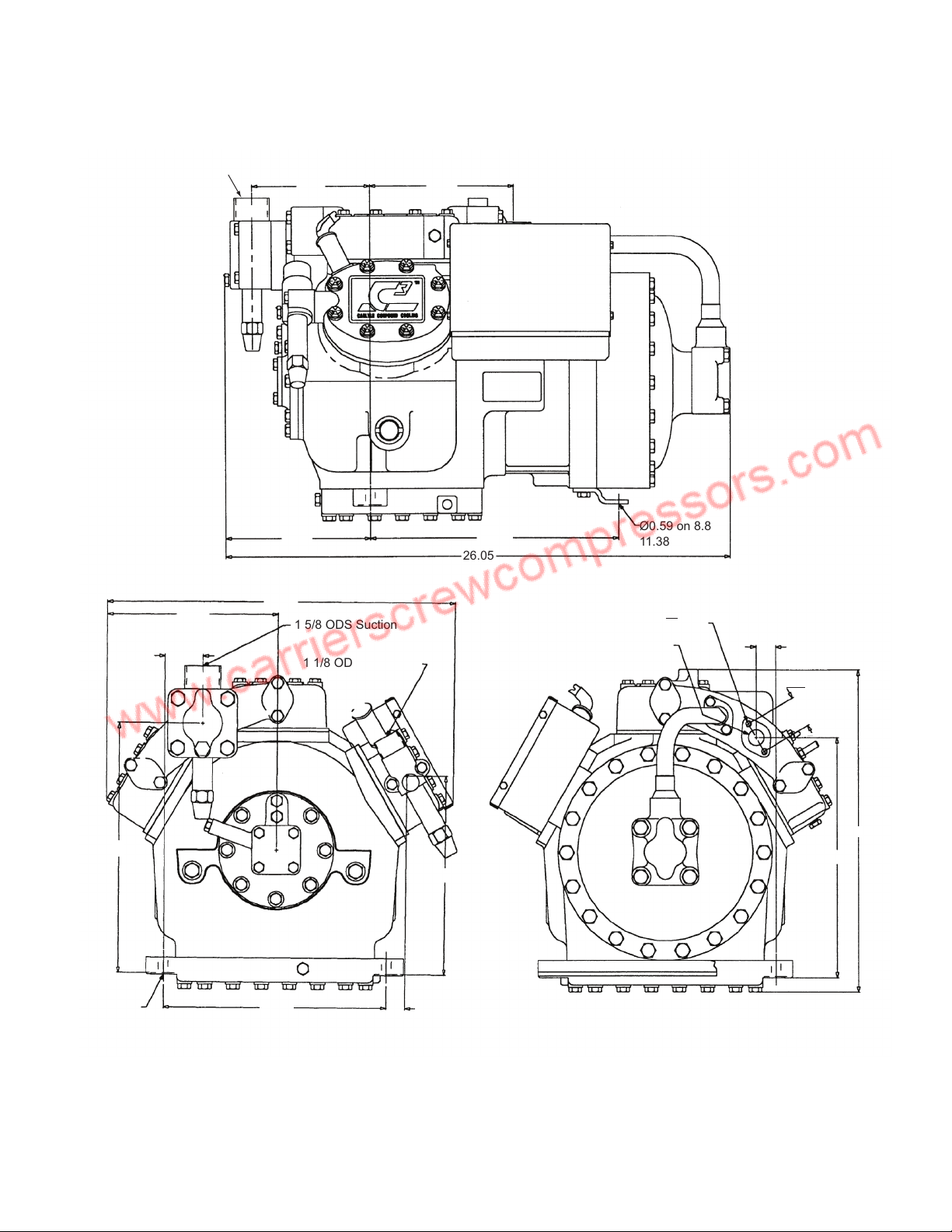
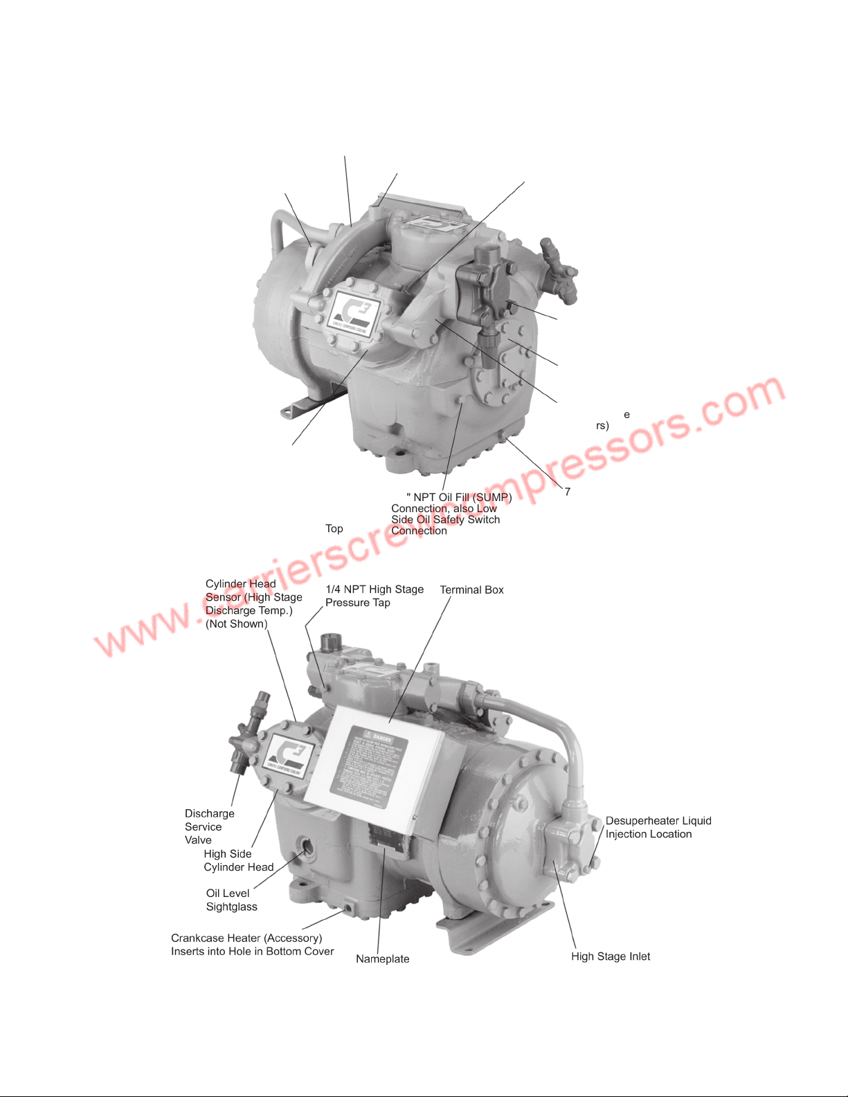
Compressor Physical Dimensions . . . . . . . . . . . 6-8
06CC Compressor (16 to 37 cfm) . . . . . . . . . . . . . 9
06CC Compressor (50 to 99 cfm) . . . . . . . . . . . . 10
1.0 System Design Considerations
1.1 Performance Data . . . . . . . . . . . . . . . . . . 11-13
1.2 Physical Data . . . . . . . . . . . . . . . . . . . . . . . . . 14
1.3 Agency Approvals . . . . . . . . . . . . . . . . . . . . . 15
1.4 Circuit Breaker Selection Table . . . . . . . . . . . 15
1.5 Refrigerants . . . . . . . . . . . . . . . . . . . . . . . . . . 16
1.6 Electrical Data Table . . . . . . . . . . . . . . . . . . . 16
1.7 Subcoolers . . . . . . . . . . . . . . . . . . . . . . . . . . . 17
1.8 Subcooler Selection . . . . . . . . . . . . . . . . . . . . 17
1.9 Subcooling Correction . . . . . . . . . . . . . . . . . . 19
1.10 Subcooler Load . . . . . . . . . . . . . . . . . . . . . . 19
1.11 Discharge Pressure Limits . . . . . . . . . . . . . . 19
1.12 Compressor Discharge Pressure Control . . 19
1.13 Variation in Capacity and Power . . . . . . . . . 19
1.14 Superheat Correction. . . . . . . . . . . . . . . . . . 19
1.15 Suction Line Accumulators. . . . . . . . . . . . . . 20
1.16 Single Compressors and Multiple Compressor
System . . . . . . . . . . . . . . . . . . . . . . . . . . . . . 20
1.17 Control Scheme . . . . . . . . . . . . . . . . . . . . . . 20
1.18 De-Superheating Expansion Valves. . . . . . . 20
1.19 Interstage Check Valves . . . . . . . . . . . . . . . 20
1.20 Capacity Control . . . . . . . . . . . . . . . . . . . . . 20
1.21 Low-Stage Discharge Gas Temperatures . . 20
1.22 Cylinder Head Cooling Fans . . . . . . . . . . . . 20
1.23 External De-Superheating . . . . . . . . . . . . . . 20
2.0 Compressor Lubrication System
2.1 Oil Separator and Oil Return . . . . . . . . . . . . .21
2.2 Oil Equalization. . . . . . . . . . . . . . . . . . . . . . . .21
2.3 Oil Pressure Safety Switch . . . . . . . . . . . . . . .21
2.4 Oil . . . . . . . . . . . . . . . . . . . . . . . . . . . . . . . . . .21
3.0 Refrigerant Control
3.1 Suction and Interstage Piping. . . . . . . . . . . . .22
3.2 Suction Line Sizing . . . . . . . . . . . . . . . . . . . . .23
3.3 Suction Pressure Range. . . . . . . . . . . . . . . . .23
3.4 Intermediate Pressure Range. . . . . . . . . . . . .23
3.5 Discharge Pressure Range. . . . . . . . . . . . . . .23
3.6 High-Low Pressure Switches . . . . . . . . . . . . .24
4.0 Compressor Features
4.1 Overtemperature Protection . . . . . . . . . . . . . .25
4.2 Overcurrent Protection . . . . . . . . . . . . . . . . . .25
4.3 Internal Pressure Relief Valves. . . . . . . . . . . .25
5.0 Compressor Wiring
Typical 06CC 16 to 37 cfm
Installation Wiring . . . . . . . . . . . . . . . . . . . . . . . . .26
Typical 06CC 50 to 99 cfm
Installation Wiring . . . . . . . . . . . . . . . . . . . . . . . . .27
6.0 Compressor Accessories. . . . .28-30
Appendix . . . . . . . . . . . . . . . . . . . . . . . . . . . . . . 31
Contents

3
This manual is for the application of the Carlyle®Com-
pound Cooling 06CC compressor. The operational limits,
required accessories, and operational guidelines are
contained in this manual and must be complied with to
stay within the compressor warranty guidelines.
The Carlyle Compound Cooling compressor offers the
highest energy efficiency available for low temperature
refrigeration when using a single compressor. A single
Carlyle Compound Cooling compressor provides the
capacity and efficiency equal to a two-compressor
booster system.
The Carlyle Compound Cooling compressor is designed
with two compression stages in a single body and utilizes
subcooling from a simple plate to plate heat exchanger
that is the system subcooler. Figure 1 shows a simple
single compressor system.
Features and Benefits
• Very high capacities and efficiencies when compared
to a single-stage, low-temperature compressor
• Very low compression ratios for low temperature
refrigeration
• Two-stage booster performance in a single-compres-
sor body
• Subcooling allows for smaller system refrigerant lines
and therefore a smaller refrigerant charge
• Simple application of subcooling
• Eliminates compressor short cycling as capacity
remains stable over a wide range of head pressures
• Can be used with R-22, R-404A, R-407A, and R-507
• No separate subcooling rack or compressor needed
How Compound Cooling Works
A variation of the two-stage booster system, the internally
compounded compressor has both the high and low
stages built into one compressor body. In this arrange-
ment, compression is accomplished in two stages, safely
and economically.
All eight 06CC models have six cylinders. Four cylinders
act as the low stage and “boost” the suction pressure
from the refrigeration load to the intermediate pressure.
The remaining two cylinders, acting as the high stage,
complete the compression to normal condensing temper-
atures. The result is lower internal losses and a compres-
sor that delivers more capacity in the same displacement.
The lower losses increase operating efficiencies. See
Fig. 1, Single Compressor System diagram, for review of
system operation.
Obsolete Compressors
Model 06CC016, 06CC018, and 06CC124 compound
compressors are not manufactured at this time. Informa-
tion on these sizes is included in this manual as a refer-
ence for existing systems.
Introduction

4
Solenoid
Valve
TXV
Expansion
Valve
Evaporator Subcooler
TXV
Bulb
TXV
Bulb
Suction
Accumulator
(Required)
Condenser
High Efficiency
Oil Separator
(Required)
Oil Return
to Crankcase
Set for Pressure Equivalent of
No Lower than 70F SCT
Y-1037
Required
for R-22
Discharge
Pressure
Regulator
Optional Liquid Injection
TXV
LOW
LOW
HIGH
➊
➌
➍
➎
➏
➐
➋
Fig. 1 — Single Compressor System
System Operation:
1. Suction gas from evaporator enters compressor suction manifold.
2. The two low stage cylinder banks compress refrigerant to intermediate pressure and flow to the intermediate
manifold.
3. A tap off the main liquid line directly expands refrigerant at condensing pressure to interstage pressure in the
subcooler.
4. Liquid on the way to the evaporator passes through the heat exchanger and is subcooled.
5. Cool suction gas at interstage pressure flows from the heat exchanger to the intermediate manifold (econo-
mizer port) where it is mixed with the refrigerant leaving the low stage cylinders. This mixing desuperheats the
intermediate stage refrigerant.
6. Desuperheated refrigerant (at intermediate pressure) flows to motor compartment and then through internal
passages to high stage cylinder block.
7. High stage cylinder compresses refrigerant and discharge to condenser.

5
06CC Model Number Significance
06CC 6 65 E 201
Design Variable:
101 = Single Pack, without Valves, with Oil
102 = Single Pack with Valves and Oil
103 = Single Pack, Service without Valves and Term. Box or Oil
201 = Single Pack, without Valves or Oil
202 = Single Pack with Valves
Electrical Characteristics:
A = 415-3-50, XL and PW
B = 415-3-50, XL
C = 415-3-50, PW
D = 208/230-3-60, XL
E = 208/230/400/460-3-50/60
F = 400/460-3-50/60, XL and PW
G = 400/460-3-50/60, XL
H = 400/460-3-50/60, PW
J = 575-3-60, XL and PW
K = 230-3-60, PW
L = 220-3-50, XL and PW
M = 220-3-50, XL
N = 220-3-50, PW
P = 220/346/380-3-50/60, XL and PW (large body)
Q = 380-3-50/60 (small body)
Displacement (in cfm at 1750 rpm) (See Note below)
Motor Size:
0 = 14 ft-lb (5 HP) 5 = 45 ft-lb (15 HP)
1 = 20 ft-lb (6.5 HP) 6 = 60 ft-lb (20 HP)
2 = 24 ft-lb (7.5 HP) 7 = 75 ft-lb (25 HP)
3 = 27 ft-lb (10 HP) 8 = 90 ft-lb (30 HP)
4 = Not Assigned
Compressor Type:
06CC = Compound Cooling Model
06CY = Service Compressor
06C8 = Compressor, Special
NOTE: USE OF “cfm” AS MODEL SIZE DESIGNATION
Carlyle uses the “cfm” designation in the model number to identify the compressor size. The
cfm values are the sixth and seventh digits of the model number. See example above.
Carlyle offers two series of compressors based on body size. The smaller compressors, from 8 to
37 cfm, are referred to as “D” size units (model number “06D”). The larger compressors, from
50 to 99 cfm, are referred to as “E” size units (model number “06E”).
The 06CC, or Carlyle®Compound Cooling compressors, are made in 16 to 37 cfm and 50 to 99 cfm
sizes. The 16 to 37 cfm compressors use “D” size bodies. The 50 to 99 cfm compressors use
“E” size bodies.
NOTE: METRIC MEASUREMENTS
The compressors are built using English units: inches, foot-pounds, pints, etc. A corresponding
metric measurement has been added to all the English units in this guide. These metric measures
are a guide only, having been rounded to the nearest whole number, and therefore are not meant
to be an exact mathematical conversion.

6
Compressor Physical Dimensions
6.08 7.37
7.36 12.78
26.02
Ø0.59 on 8.88 &
11.38 Centers
1 3/8 ODS
16.90
8.26
7/8 ODS Dischage
1 3/8 ODS Suction
13.37
1.72
2X Ø 0.5 11.37
0.57
9.88
15.98
11.97
1.17
1.625
Economizer Port
2X 5/16-18 UNC-2B 0.56
NOTE: Dimensions are in inches.
Fig. 2 — 06CC016, 018, 124 Models

7
Compressor Physical Dimensions (cont)
5.98 7.42
1 5/8 ODS
7.38 12.78
26.05
Ø0.59 on 8.88 &
11.38 Centers
17.67
8.64 1 5/8 ODS Suction
1 1/8 ODS Discharge
1.91
12.76
11.38
2X Ø0.50 0.95
12.23
16.41
1.02
1.625
Economizer Port
10.15
2X 5/16-18 UNC-2B 0.56
NOTE: Dimensions are in inches.
Fig. 3 — 06CC017, 025, 228, 337 Models

8
Compressor Physical Dimensions (cont)
NOTE: Dimensions are in inches.
Fig. 4 — 06CC550, 665, 675, 899 Models

9
06CC Compressor (16 to 37 cfm)
Connection from
Subcooling Heat
Exchanger
Interstage
Manifold
1/2 - 13 UNC -
Lifting Lug Connection
(Lug not supplied
with compressor)
1/4 NPT Interstage
Pressure Tap
(Includes Schrader
Fitting to Relieve
Crankcase Pressure)
Suction Valve
Location
1/4" NPT High Side
Oil Safety Switch
Connection
Suction Manifold
(To Low Stage
Cylinders)
7/16" - 20 SAE Oil Drain
Connection (Adaptor
Part No. DE14CA126)
1/4" NPT Oil Fill (SUMP)
Connection, also Low
Side Oil Safety Switch
Connection
1/4-NPT Low Stage
Pressure Tap (Not shown)
Bottom of Cylinder
Head has a Boss and
1/4 NPT Just Like the Top
Fig. 5 — 06CC Compressor (16 to 37 cfm)

10
06CC Compressor (50 to 99 cfm)
Suction Valve
Location
1/4" NPT Oil Pump
Pressure Connection
Oil Pressure Access
Tee to be Installed in
this Connection
High Side Connection
of Oil Pressure
Switch to be Connected
to Flared End of
Installed Tee
1/4" NPT Intermediate
Stage Pressure
Connection Factory
Supplied Schrader
Type Fitting
Oil Level
Sightglass
Discharge Valve
Location
7/16"-20 SAE Oil Drain
Connection (Adapter
Part No. DE14CA126)
1/4" NPT (2) Connections
(1) Above Sightglass
(1) Above Blank Plate
Used for:
(A) Oil Fill Connection
(B) Low Side Oil Safety
Switch Connection
Crankcase Heater (Accessory)
Inserts into Hole in Bottom Cove
r
Terminal
Box
1/4" High Stage
Pressure Tap
Nameplate
Cylinder Head
Sensor (High Stage
Discharge Temp.)
Fig. 6 — 06CC Compressor (50 to 99 cfm)

11
1.1 Performance Data
Performance data for Carlyle's 06CC models assumes
that there is de-superheating liquid injection when
needed. The performance data also assumes that there
is an applied subcooler with leaving liquid refrigerant
temperatures of 40 F. At certain operating conditions, the
intermediate-stage pressures are too high to achieve
40 F liquid refrigerant leaving the subcooler and entering
the TXV (thermal expansion valve). In these instances,
the performance data assumes that the liquid refrigerant
temperature is equal to the Saturated Interstage Temper-
ature (SIT) plus 10 F. The published performance data
includes all subcooling and de-superheating loads. The
published mass flow rates are evaporator mass flow
rates.
Performance data is available for both 50 Hz and 60 Hz
applications. As with all reciprocating compressors, a
'run-in' period of 50 to 100 hours may be required to
obtain the published performance.
To aid designers, Carlyle has provided interstage pres-
sure tables for R-22, R-407A, R-404A and R-507. Fur-
ther, Carlyle's 'Solutions' software is capable of
calculating the 06CC model performance with varying liq-
uid temperatures. The AHRI coefficients are available for
Carlyle's 06CC models upon request from Carlyle's
Applications Engineering department.
R-22 Approximate Interstage Pressure ± 10 psig (0.7 bar) with Subcooler
* Indicates vacuum.
† Absolute pressure where 1 bar = ATM (Atmospheric) Pressure.
SATURATED
SUCTION
TEMP
SUCTION
PRESSURE
PSIG
(BARS)
SATURATED CONDENSING TEMPERATURE
60 F
(16 C)
70 F
(21 C)
80 F
(27 C)
90 F
(32 C)
100 F
(38 C)
110 F
(43 C)
120 F
(49 C)
130 F
(54 C)
CONDENSING PRESSURE, psig (bars)
101.6
(7.01)
121.4
(8.37)
143.6
(9.90)
168.4
(11.61)
195.9
(13.51)
226.4
(15.61)
259.9
(17.92)
296.8
(20.40)
-60 F
(-51 C)
11.9*
(0.610)†
- - - 183.1 210.6 241.1 274.6 311.5
-55 F
(-48 C)
9.2*
(0.795)†
17
(1.17)
20
(1.38)
23
(1.59)
26
(1.79)
28
(1.93)
31
(2.14)
35
(2.41)
38
(2.62)
-50 F
(-45 C)
6.1*
(0.886)†
20
(1.38)
23
(1.59)
25
(1.72)
29
(2.0)
32
(2.21)
35
(2.41)
38
(2.62)
42
(2.89)
-45 F
(-43 C)
2.7*
(0.924)†
22
(1.52)
25
(1.72)
28
(1.93)
32
(2.21)
35
(2.41)
38
(2.62)
42
(2.89)
46
(3.17)
-40 F
(-40 C)
0.5
(0.034)
25
(1.72)
28
(1.93)
31
(2.14)
35
(2.41)
38
(2.62)
42
(2.89)
46
(3.17)
50
(3.44)
-35 F
(-37 C)
2.6
(0.179)
27
(1.86)
31
(2.14)
34
(2.34)
38
(2.62)
42
(2.89)
46
(3.17)
50
(3.44)
54
(3.72)
-30 F
(-34 C)
4.9
(0.338)
30
(2.07)
34
(2.34)
38
(2.62)
42
(2.89)
46
(3.17)
50
(3.44)
54
(3.72)
59
(4.07)
-25 F
(-32 C)
7.4
(0.510)
33
(2.28)
37
(2.55)
38
(2.62)
42
(2.89)
46
(3.17)
50
(3.44)
54
(3.72)
59
(4.07)
-20 F
(-29 C)
10.1
(0.697)
36
(2.48)
40
(2.76)
44
(3.03)
49
(3.38)
54
(3.72)
58
(4.0)
63
(4.34)
68
(4.69)
-15 F
(-26 C)
13.2
(0.910)
39
(2.69)
43
(2.97)
48
(3.31)
53
(3.66)
58
(4.0)
63
(4.34)
68
(4.69)
73
(5.03)
-10 F
(-23 C)
6.5
(1.138)
42
(2.90)
47
(3.24)
52
(3.59)
57
(3.93)
62
(4.28)
67
(4.62)
73
(5.03)
79
(5.45)
1.0 System Design Considerations

12
R-507/R-404A Approximate Interstage Pressure ± 10 psig (0.7 bar) with Subcooler
* Indicates vacuum.
† Absolute pressure where 1 bar = ATM (Atmospheric) Pressure.
SATURATED
SUCTION
TEMP
SUCTION
PRESSURE
PSIG
(BARS)
SATURATED CONDENSING TEMPERATURE
60 F
(16 C)
70 F
(21 C)
80 F
(27 C)
90 F
(32 C)
100 F
(38 C)
110 F
(43 C)
120 F
(49 C)
Condensing Pressure, psig (bars)
129.7
(9.96)
153.6
(11.61)
180.3
(13.45)
210.2
(15.51)
243.5
(17.81)
280.6
(20.37)
321.9
(23.21)
-60 F
(-51 C)
5.9*
(0.814)†
26
(2.81)
30
(3.08)
33
(3.29)
37
(3.57)
40
(3.77)
44
(4.05)
48
(4.32)
-55 F
(-48 C)
2.3*
(0.929)†
29
(3.01)
33
(3.29)
37
(2.57)
40
(3.77)
44
(4.05)
48
(4.32)
53
(4.67)
-50 F
(-45 C)
0.9*
(1.08)†
33
(3.29)
37
(3.57)
40
(3.77)
45
(4.19)
49
(4.39)
53
(4.67)
58
(5.01)
-45 F
(-43 C)
3.1
(1.23)
35
(3.43)
39
(3.70)
44
(4.05)
48
(4.32)
53
(4.67)
57
(4.94)
62
(5.29)
-40 F
(-40 C)
5.5
(1.39)
39
(3.70)
44
(4.05)
48
(4.32)
53
(4.67)
58
(5.01)
63
(5.36)
68
(5.70)
-35 F
(-37 C)
8.2
(1.58)
43
(3.98)
47
(4.26)
52
(4.60)
57
(4.94)
62
(5.29)
68
(5.70)
73
(6.05)
-30 F
(-34 C)
11.1
(1.78)
46
(4.19)
51
(4.53)
56
(4.88)
61
(5.22)
67
(5.63)
73
(6.05)
78
(6.39)
-25 F
(-32 C)
14.3
(2.00)
50
(4.46)
55
(4.81)
60
(5.15)
66
(5.57)
72
(5.98)
78
(6.39)
84
(6.81)
-20°F
(-29°C)
17.8
(2.24)
54
(4.74)
59
(5.08)
65
(5.50)
71
(5.91)
77
(6.32)
83
(6.74)
90
(7.22)
-15 F
(-26 C)
21.7
(2.51)
58
(5.01)
64
(5.43)
70
(5.84)
76
(6.26)
82
(6.67)
89
(7.15)
96
(7.63)
-10 F
(-23 C)
25.8
(2.79)
62
(5.29)
68
(5.70)
74
(6.12)
81
(6.60)
88
(7.08)
95
(7.57)
102
(8.05)

13
R-407A Approximate Interstage Pressure ± 10 psig (0.7 bar) with Subcooler
* Indicates vacuum.
† Absolute pressure where 1 bar = ATM (Atmospheric) Pressure.
SATURATED
SUCTION
TEMP
SUCTION
PRESSURE
PSIG (BAR)
SATURATED CONDENSING TEMPERATURE
60 F
(16 C)
70 F
(21 C)
80 F
(27 C)
90 F
(32 C)
100 F
(38 C)
110 F
(43 C)
120 F
(49 C)
130 F
(54 C)
Condensing Pressure, psig (bars)
125.2
(8.63)
148.8
(10.26)
175.3
(12.09)
204.8
(14.12)
237.6
(16.38)
273.9
(18.88)
314.0
(21.65)
357.9
(24.68)
-60 F
(-51 C)
14.5*
(0.52)†
8
(1.5)
10
(1.7)
11
(1.8)
12
(1.8)
13
(1.9)
15
(2.0)
19
(2.3)
36
(2.8)
-55 F
(-48 C)
11.9*
(0.61)†
10
(1.7)
13
(1.9)
14
(2.0)
15
(2.1)
17
(2.2)
20
(2.4)
24
(2.7)
41
(3.1)
-50 F
(-45 C)
8.9*
(0.71)†
12
(1.9)
15
(2.1)
18
(2.2)
19
(2.3)
21
(2.5)
24
(2.7)
29
(3.0)
46
(3.5)
-45 F
(-43 C)
5.6*
(0.82)†
15
(2.0)
19
(2.3)
21
(2.5)
23
(2.6)
26
(2.8)
29
(3.0)
34
(3.3)
51
(3.8)
-40 F
(-40 C)
2.1*
(0.94)†
18
(2.2)
22
(2.5)
25
(2.7)
27
(2.9)
30
(3.1)
34
(3.3)
39
(3.7)
56
(4.2)
-35 F
(-37 C)
1.0
(1.08)
21
(2.4)
26
(2.8)
29
(3.0)
32
(3.2)
35
(3.4)
39
(3.7)
44
(4.0)
62
(4.5)
-30 F
(-34 C)
3.3
(1.24)
25
(2.7)
30
(3.1)
34
(3.4)
37
(3.6)
40
(3.8)
44
(4.1)
49
(4.4)
67
(4.9)
-25 F
(-32 C)
5.7
(1.41)
29
(3.0)
35
(3.4)
39
(3.7)
43
(3.9)
46
(4.2)
50
(4.5)
55
(4.8)
73
(5.4)
-20 F
(-29 C)
8.5
(1.60)
34
(3.4)
40
(3.8)
45
(4.1)
49
(4.4)
52
(4.6)
56
(4.9)
62
(5.3)
80
(5.8)
-15 F
(-26 C)
11.5
(1.81)
40
(3.7)
46
(4.2)
51
(4.6)
55
(4.8)
59
(5.1)
63
(5.4)
69
(5.8)
87
(6.3)
-10 F
(-23 C)
14.9
(2.04)
46
(4.2)
53
(4.7)
59
(5.1)
63
(5.4)
67
(5.6)
71
(5.9)
77
(6.3)
94
(6.8)

14
1.2 Physical Data
LEGEND
NOTES:
1. Approximate condensing temperature ranges. CHECK ACTUAL
PERFORMANCE DATA FOR ANY NEW APPLICATION ESPE-
CIALLY AT OR NEAR UPPER OR LOWER LIMIT: L.T. =70 to 130 F
(21 to 55 C).
2. To provide a 6-cylinder body needed for Carlyle®Compound Cooling
compressor, the normal 4-cycle model 16, 18 and 50 cfm compres-
sors were built using the 24 and 65 cfm 6-cylinder bodies, respec-
tively. The actual cfm reduction is achieved by modifying the running
gear.
3. R404A/R-507 CANNOT be used in the small “D” body size Com-
pound Cooling compressors (16 to 37 cfm), manufactured prior to
SerIal No. 2099J. See Section 1.5.
4. R-134a and R-12 CANNOT be used in any Compound Cooling
compressor.
CARRIER /
CARLYLE MODEL
NUMBER
STANDARD SERVICE
REPLACEMENT
MODEL
SUCTION TEMPERATURE RANGE ...(See Note 1)
R-404A/R-507 R-134a R-22 and R-407A
F (See
Note 3)
C (See
Note 3)
FCFC
06CC016...(See Note 2) 06CY016... -40 to -10 -40 to -23 (See Note 4) -40 to -10 -40 to -23
06CC017... 06CY017... -40 to -10 -40 to -23 -40 to -10 -40 to -23
06CC018...(See Note 2) 06CY018... -40 to -10 -40 to -23 -40 to -10 -40 to -23
06CC124... 06CY124... -60 to -10 -51 to -23 -40 to -10 -40 to -23
06CC125... 06CY125... -60 to -10 -51 to -23 -40 to -10 -40 to -23
06CC228... 06CY228... -60 to -10 -51 to -23 -40 to -10 -40 to -23
06CC337... 06CY337... -60 to -10 -51 to -23 -40 to -10 -40 to -23
06CC550...(See Note 2) 06CY550... -40 to -10 -40 to -23 -40 to -10 -40 to -23
06CC665... 06CY665... -60 to -10 -51 to -23 -40 to -10 -40 to -23
06CC675... 06CY675... -60 to -10 -51 to -23 -40 to -10 -40 to -23
06CC899... 06CY899... -60 to -10 -51 to -23 -40 to -10 -40 to -23
CARRIER /
CARLYLE
MODEL
NUMBER
MOTOR
SIZE
DISPLACEMENT AT
1750 RPM NO.
OF
CYL
BORE STROKE
OIL
CHARGE
NET
WEIGHT
BODY
SIZEHP kW CFM L/M CFH
L/H
(1,000) in. mm in. mm Pints Liters lb kg
06CC016...
(See Note 2)
5 3.7 15.9 450 954 27.01 6 2 50.8 1 1/4 31.8 9.5 4.5 330 150 D
06CC017... 5 3.7 15.9 450 954 27.01 6 2 50.8 1 1/4 31.7 9.5 4.5 330 150 D
06CC018...
(See Note 2)
5 3.7 18.3 518 1100 31.09 6 2 50.8 1 15/32 37.3 9.5 4.5 325 147 D
06CC124... 6 1/2 4.9 23.9 677 1435 40.60 6 2 50.8 1 1/4 31.8 9.5 4.5 335 152 D
06CC125... 6 1/2 4.9 23.9 677 1435 40.60 6 2 50.8 1 1/4 31.8 9.5 4.5 330 150 D
06CC228... 7 1/2 5.6 28 793 1680 47.57 6 2 50.8 1 15/32 37.3 9.5 4.5 340 154 D
06CC337... 10 7.5 37.1 1050 2225 63.03 6 2 50.8 1 15/16 49.2 9.5 4.5 345 156 D
06CC550...
(See Note 2)
15 11.2 50.3 1424 3016 85.45 6 2 11/16 68.3 1 63/64 50.4 19 9.0 545 247 E
06CC665... 20 14.9 68.3 1934 4096 116.0 6 2 11/16 68.3 1 63/64 50.4 19 9.0 555 252 E
06CC675... 20 14.9 75.4 2135 4524 128.1 6 2 11/16 68.3 2 3/16 55.6 19 9.0 555 252 E
06CC899... 30 22.4 99.0 2803 5940 168.2 6 2 11/16 68.3 2 7/8 73.0 19 9.0 580 263 E
CFM — Cubic Feet Per Minute
L/H — Liters Per Hour
L/M — Liters Per Minute

15
1.3 Agency Approvals
All Carlyle 06CC models are UL (Underwriters Laborato-
ries) and CSA (Canadian Standards Association)
approved with R-22, R-407A, R-404A and R-507. The 50
to 99 cfm, 06CC models are supplied without included
motor protection. The 50 to 99 cfm, 06CC models require
the use of Carlyle-approved motor protection to maintain
UL approval. Approved motor protection devices / acces-
sories are shown in the Circuit Breaker Selection Table.
The use of alternate overcurrent protection devices must
be approved by the Carlyle Applications Engineering
department. The application of alternate overcurrent
devices without Carlyle's approval will VOID warranty.
UL File No. SA4936
All Carlyle 06CC models meet CE requirements for the
Low-Voltage and Machinery Directive.
1.4 Circuit Breaker Selection Table
06CC (50 to 99 cfm) 3 Phase Electrical Specifications
LEGEND
* Circuit breaker that requires “ring” terminal connection.
NOTES:
1. Compressor must-trip (MT) amps and RLA values are maximum figures.
2. LRA values for PW second winding = 1/2 the LRA XL value.
3. 3-Pole XL circuit breakers shown, other 3-Pole XL alternatives and 6-Pole
PW breakers available. Terminal lugs for circuit breakers available in pack-
age 06EA660152.
4. Recommended RLA value shown is determined by: circuit breaker must trip
value ÷ 1.40. Use this recommended (and minimum) RLA value to deter-
mine name plate stamping, minimum contactor sizing and wire sizing. REC-
OMMENDED RLA FOR 06CC COMPRESSORS EQUALS: MUST-TRIP
(MT) OF CARLYLE APPROVED OVERCURRENT DEVICE BEING USED ÷
1.40.
5. Compressor operating amps at any specific condition can only be deter-
mined from a performance curve.
6. Ohm values for resistance are approximate and shown for reference pur-
poses only. Motors from different vendors and motors of different efficiencies
can differ up to 15% from data shown.
Allowable Operating Ranges
COMPRESSOR
INFORMATION
RECOMMENDED
CIRCUIT BREAKERS
OVERLOAD
INFORMATION
06CC
Models
Voltage HP See Note 1 See Note 2 Recom.
Part No.
Must
Hold
Amps
Must
Trip
Amps
LRA See
Note 3
Recom.
RLA
Alternate
Part No.
Must
Hold
Amps
Must
Trip
Amps
LRA Part Number Req.
Dial
Setting
Max.
Must
Trip
Amps
Max.
RLA
LRA
XL
LRA PW
1st
Winding
06CC550J
06CC550F
06CC550E
06CC550E
575
400/460
208/230
460
15
27
32
68
32
22
26
54
26
98
142
283
142
59
85
170
85
HH83XB438*
HH83XB414*
HH83XB455*
HH83XB414*
23
27
59
27
27
32
68
32
86
145
245
145
19.3
22.9
45.6
22.9
HH83XB689
HH83XB698
HH83XB697
HH83XB698
23
27
59
27
27
32
68
32
86
145
245
145
06EA907185
06EA907185
06EA907186
06EA907185
24
28
60
28
06CC665J
06CC665F
06CC665E
06CC665E
575
400/460
208/230
460
20
38
50
100
50
30
40
80
40
120
173
345
173
72
104
207
104
HH83XA461*
HH83XB437*
HH83XB376*
HH83XB437*
33
43
73
43
38
50
85
50
124
176
333
176
27.1
35.7
60.7
35.7
—
HH83XB606
—
HH83XB606
—
43
—
43
—
49
—
49
—
173
—
173
06EA907185
06EA907186
06EA907186
06EA907186
33
44
89
44
06CC675J
06CC675F
06CC675E
06CC675E
575
400/460
208/230
460
20
38
50
100
50
30
40
80
40
120
173
345
173
72
104
207
104
HH83X461
HH83XB437*
HH83XB378*
HH83XB437*
33
43
77
43
38
50
89
50
124
176
365
176
27.1
35.7
63.6
35.7
—
HH83XB606
—
HH83XB606
—
43
—
43
—
49
—
49
—
173
—
173
06EA907185
06EA907186
06EA907186
06EA907186
33
44
89
44
06CC899J
06CC899F
06CC899E
06CC899E
575
400/460
208/230
460
30
46
58
113
58
46
58
113
58
176
253
506
253
106
152
304
152
HH83XA430
HH83XB432*
HH83XC406
HH83XB432*
50
63
122
63
58
73
141
73
168
240
464
240
41.4
52.1
100.7
52.1
HH83XA469
HH83XB604
—
HH83XB604
46
63
—
63
53
73
—
73
164
240
—
240
06EA907186
06EA907186
06EA907187
06EA907186
51
65
125
65
LRA — Locked Rotor Amps
MH — Must Hold Amps
MT — Must Trip Amps
PW — Part-Winding Start
RLA — Rated Load Amps
XL — Across the Line Start
NOMINAL VOLTAGE MAXIMUM MINIMUM
208/230 254 187
460 529 414
575 661 518
400 (50 Hz) 460 342
200 (50 Hz) 230 180

16
1.5 Refrigerants
All 06CC compressors built after 2099J are approved for
R-22, R-404A, R-407A, and R-507 except compressors
in the 16 to 37 cfm range. Compressors in this size range
cannot be used with R-404A, R-407A and R-507 prior to
serial number 2099J- - - - without installing a retrofit com-
pressor valve plate (part number 06CY660-002) kit.
1.6 Electrical Data Table
LEGEND
NOTES:
1. RLA (rated load amps) value shown for new high-efficiency mod-
els is MCC ÷ 1.56 = RLA. Use this recommended (and minimum)
RLA value to determine nameplate stamping, minimum contactor
sizing and wire sizing.
2. Compressor operating amps at any specific condition can only be
determined from a performance curve.
3. RLA values for 06D compressor protected by calibrated circuit
breaker will depend must-trip value of circuit breaker.
4. Ohm values shown for resistance are approximate and shown for
reference only. Motors from different vendors and motors of differ-
ent efficiencies can differ up to 15% from data shown.
Allowable Operating Range
COMPRESSOR MOTOR DATA
Compressor
Model
Max
kW HP
Electrical Data
Overload Carlyle
Part No.
Part No.
T.I. No.Volts MCC RLA LRA
Motor Winding
Resistance
(Ohms)
06CC016J101
D101
G101
6.25 5
575
208/230
460
10.8
27.0
13.5
6.9
17.3
8.7
40
100
50
3.3
0.54
2.1
HN69GZ032
HN69GZ024
HN69GZ014
8347A23-42
8347A23-63
8347A23-53
06CC017J101
D101
G101
6.25 5
575
208/230
460
10.8
27.0
13.5
6.9
17.3
8.7
40
100
50
3.3
0.54
2.3
HN69GZ032
HN69GZ024
HN69GZ014
8347A23-42
8347A23-63
8347A23-53
06CC018J101
D101
G101
6.25 5
575
208/230
460
10.8
27.0
13.5
6.9
17.3
8.7
40
100
50
3.3
0.54
2.1
HN69GZ032
HN69GZ024
HN69GZ014
8347A23-42
8347A23-63
8347A23-53
06CC124J101
D101
G101
9.18 6.5
575
208/230
460
13.2
33.0
16.5
8.5
21.2
10.6
64
160
80
2.6
0.42
1.7
HN69GZ037
HN69GZ214
HN69GZ038
8347A23-40
8348A23-9
8347A23-18
06CC125J101
D101
G101
9.18 6.5
575
208/230
460
13.2
33.0
16.5
8.5
21.2
10.6
64
160
80
2.6
0.42
1.7
HN69GZ037
HN69GZ214
HN69GZ038
8347A23-40
8348A23-9
8347A23-18
06CC228J101
D101
G101
12.8 7.5
575
208/230
460
16.7
41.6
20.9
10.2
26.7
13.4
79
198
99
2.0
0.31
1.3
HN69GZ004
HN69GZ306
HN69GZ010
8347A23-19
8347B23-13
8347A23-29
06CC337J101
D101
G101
16.5 10
575
208/230
460
18.8
46.5
23.3
12.1
29.8
14.9
91
228
114
1.7
0.26
1.0
HN69GZ025
HN69GZ309
HN69GZ024
8347A23-31
8347B23-11
8347A23-63
LRA — Locked Rotor Amps
MCC — Maximum Continuous Current
RLA — Rated Load Amps
TI — Texas Instruments
NOMINAL
VOLTAGE
MAXIMUM
VOLTAGE
MINIMUM
VOLTAGE
206/230 254 187
575 661 518
400 (50 Hz) 460 342
200 (50 Hz) 230 180

17
1.7 Subcoolers
The subcooler in these systems is controlled through the
use of a single TXV (thermal expansion valve) that is fed
from a 'branch' off of the main liquid line. A small amount
of liquid refrigerant is expanded through the TXV (into the
subcooler / economizer) to cool the remaining liquid
refrigerant. The suction gas from that work is typically
superheated ~ 25°F (TXV adjustment) then flows from
the subcooler into the interstage section of the 06CC
model compressor, providing some (or all) of the de-
superheating needed for the refrigerant gas entering the
motor compartment. A normally closed liquid line sole-
noid valve must be installed prior to the subcooler TXV.
The solenoid valve must be controlled to close when all
of the compressors are OFF.
The subcooler must be connected in a 'parallel-flow' con-
figuration to reduce the potential for excessively super-
heated suction gas returning from the subcooler to the
interstage connection of the compressor. Highly super-
heated gas entering the interstage can cause TXVs to
operate in an unstable manner. Variation in condensing
pressures (as seen in air-cooled systems) will affect inter-
stage pressures in the system and may result in varying
liquid temperatures leaving the subcooler.
1.8 Subcooler Selection
Two-stage systems have the inherent benefit of being
able to utilize interstage subcooling and de-superheating
through the use of a subcooler. The application of a liquid
subcooler is strongly recommended for all Carlyle®Com-
pound Cooling 06CC models. Providing liquid subcooling
from a second compressor group is not needed and not
recommended with 06CC model compressors. Shown in
Fig. 7 is a diagram of a subcooler cycle. The liquid refrig-
erant exiting the condenser is routed to the subcooler
and sub-cooled for use in the evaporator(s). To accom-
plish this task, a small quantity of the same liquid refriger-
ant is taken from the main liquid line (prior to entering the
subcooler). This liquid is expanded into the subcooler to
reduce the overall liquid temperature of the system. This
subcooling method allows for the work to be performed at
the higher interstage pressure, which is more efficient,
resulting in increased compressor capacity and EER
(energy efficiency ratio). A tap off the main liquid line is
directly expanded across the subcooler from condensing
pressure to interstage pressure. The subcooling is done
at interstage pressure where the refrigerant can be com-
pressed more efficiently, therefore increasing the com-
pressor capacity and energy efficiency ratio.
Solenoid
Valve
TXV
Subcooler
TXV
Bulb
Subcooler Liquid
to Evaporate
To Compressor Interstage
(Economizer Connection)
Main
Condenser
Line
Fig. 7 — Subcooler Cycle

18
Solenoid
Valve
Expansion
Valve
Expansion
Valve
Evaporator Subcooler
TXV
Bulb
TXV
Bulb
Condenser
Strongly Recommended
Set for Pressure Equivalent of
No Lower than 70F SCT
LOW
LOW
HIGH
LOW
LOW
HIGH
Solenoid
Valve Desuperheating
Valve
(Sporlan Y-1037)
High Efficiency Oil Separator
Oil Return to Compressor Crankcase
Discharge
Pressure Regulator
Solenoid
Valve
TXV
Expansion
Valve
Evaporator Subcooler
TXV
Bulb
TXV
Bulb
Suction
Accumulator
(Required)
Condenser
High Efficiency
Oil Separator
(Required)
Oil Return
to Crankcase
Set for Pressure Equivalent of
No Lower than 70F SCT
Y-1037
Required
for R-22
Discharge
Pressure
Regulator
Optional Liquid Injection
TXV
LOW
LOW
HIGH
Strongly Recommended
Set for Pressure Equivalent of
No Lower than 70F SCT
Fig. 9 — Carlyle Compound Cooling System Piping Multiple Compressor Systems
Fig. 8 — Single Compressor Carlyle®Compound Cooling System Piping

19
1.9 Subcooling Correction
Performance rating tables for the 06CC models are
developed assuming that the liquid temperature is at 40 F
(4 C). If the design liquid temperature is other than 40 F
(4 C), corrections of the estimated performance may be
accomplished by the following methods:
1. For R-22 and R-407A, decrease compressor capac-
ity (as shown in the published performance data) by
3% for each 10°F (12°C) increase in liquid refrigerant
temperature (measured entering the expansion
valve).
2. For R-404A/R-507, decrease compressor capacity
(as shown in the published performance data) by 6%
for each 10°F (12°C) increase in liquid refrigerant
temperature (measured entering the expansion
valve).
3. Calculate the change in refrigerant enthalpy at the
new liquid temperatures and multiply that by the
mass flow rate (as shown in the published perfor-
mance data). Mass flow rates in the 06CC models
have very small fluctuations based on liquid tempera-
tures because they operate near their maximum vol-
umetric efficiency.
1.10 Subcooler Load
Carlyle offers brazed-plate heat exchangers for use on
single and multiple compressor systems. These heat
exchangers should be sized based on the estimated sub-
cooling load. A listing of the available heat exchangers is
provided in the “6.0 Compressor Accessories” section of
this document. The subcooler load may be estimated by
any of the following methods:
1. The subcooling load for R-22 and R-407A systems is
approximately equal to 25 to 30 percent of the com-
pressor capacity for the given condition. The sub-
cooling load for R-404A/R-507 systems is
approximately equal to 35 to 40 percent of the com-
pressor capacity for the given condition.
2. The actual subcooling load may be calculated by
multiplying the compressor mass flow rate by the
change in liquid enthalpy (between entering and
leaving liquid temperature) across the subcooler.
3. Carlyle’s Solutions Software calculates the subcooler
load for the system designer.
1.11 Discharge Pressure Limits
Two-stage 06CC models may be applied in systems that
utilize air-cooled condensers. Carlyle limits the maximum
design saturated discharge temperature in these systems
to 130 F and the minimum design saturation discharge
temperature to 70 F. Allowing saturated discharge tem-
peratures to fall below 70 F does not significantly affect
energy usage, is not recommended, and may lead to
increased valve stresses and potential valve failure.
1.12 Compressor Discharge Pressure
Control
Stable control of the discharge pressure in the 06CC
models has been shown to significantly increase com-
pressor reliability. Carlyle strongly recommends the use
of a discharge pressure regulators for all R-22 applica-
tions that utilize multiple 06CC models. Carlyle requires
the use of discharge pressure regulators for all R-407A,
R-404A, and R507 applications that utilize multiple 06CC
models. All single 06CC compressor applications require
the use of a discharge pressure regulator. The pressure
regulator must be installed so that the discharge pres-
sure of the compressor will not fall below the 70 F satu-
rated discharge temperatures noted in “1.11 Discharge
Pressure Limits” section. All systems that apply Hot Gas
Defrost designs require the use of a discharge pressure
regulator.
1.13 Variation in Capacity and Power
All 06CC model compressors have relatively small varia-
tions in compressor capacity across the full range of
acceptable saturated discharge temperatures (SDT).
Compressor capacity varies approximately 6% between
the maximum and minimum allowable saturated dis-
charge temperatures (130 F SDT and 70 F SDT, respec-
tively). This small variation in compressor capacity
results in significantly reducing ON/OFF compressor
cycling, when compared to similarly designed single-
stage compressor applications, while still maintaining
very high EERs.
1.14 Superheat Correction
The published 06CC Model Performance tables for
Carlyle’s 06CC models are generated assuming a return
gas temperature (RGT) of 65 F. Designs that have
Important!
Carlyle published 06CC Model Performance Data
assumes that the liquid temperature is at 40 F or
at the Saturated Interstage Temperature (SIT) +
10°F, whichever is higher. These assumptions are
based on the fact that the subcooler cannot oper-
ate at saturated temperatures lower than the suc-
tion of the compressor interstage. The suction of
the subcooler is connected to the interstage
pressure port of the 06CC models which acts to
limit the temperatures that are achievable in the
subcooler. For more detailed information, see the
Interstage Pressure Tables on pages 11-13.

20
significantly cooler RGTs will have a slight decrease in
compressor capacity when compared to the published
06CC Model Performance tables.
1.15 Suction Line Accumulators
The design of Carlyle’s 06CC model compressors draw
suction gas directly into the low-stage cylinders. Labora-
tory testing has shown that the valves are tolerant to liq-
uid flooding; however, extreme flooding and liquid “slugs”
may cause damage to the compressor. All 06CC models
must be protected from liquid refrigerant and oil “slugs.”
1.16 Single Compressors and Multiple
Compressor System
All single 06CC compressor systems require the applica-
tion of a suction line accumulator. All multiple 06CC com-
pressor systems require the use of a suction line
accumulator or functionally equivalent protection such as
an over-sized suction line manifold. Carlyle recommends
that a suction line accumulator is applied.
1.17 Control Scheme
Properly designed control systems are important to
ensure reliable and efficient 06CC compressor operation.
Please review the following control scheme designs:
Single-Compressor Systems (Fig. 8)
Carlyle requires that single, 06CC compressor systems
are applied with a discharge pressure regulating valve.
Discharge pressure regulating valves prevent the dis-
charge pressure of the compressor from falling below the
required minimum pressures (70 SDT equivalent) in sys-
tems that do not utilize condenser fan controls.
Multiple-Compressor Systems (Fig. 9)
Carlyle strongly recommends that R-22 systems utilizing
multiple / parallel 06CC compressors are applied with a
discharge pressure regulating valve. Carlyle requires that
all HFC / POE systems utilizing multiple / parallel 06CC
compressors, are applied with a discharge pressure reg-
ulating valve (or functional equivalent such as condenser
fan controls). The application of these discharge pres-
sure controls prevents the discharge pressure of the
compressor from falling below the required minimum
pressures (70 SDT equivalent).
1.18 De-Superheating Expansion
Valves
Liquid injection is required for some applications to con-
trol discharge gas temperatures. Liquid injection is
accomplished through the use of Carlyle recommended
de-superheating expansion valves. These valves are
designed to operate only when the suction gas from the
subcooler cannot absorb enough heat to control the com-
pressor's leaving discharge gas temperatures between
200 F and 230 F. See Section 6.0.
If a de-superheating valve is applied, a normally closed
liquid line solenoid valve must be installed prior to the de-
superheating valve (with the sensing bulb attached to the
discharge tubing approximately 6 inches from the dis-
charge service valve). This solenoid valve must be con-
trolled to close whenever the associated compressor is
OFF. De-superheating valves are directly connected to
the 4-bolt flange at the motor end cover of the
compressor.
1.19 Interstage Check Valves
Interstage check valves are no longer required with
Carlyle's 06CC model compressors.
1.20 Capacity Control
Suction cut-off unloading is not available with Carlyle's
06CC models. Variable frequency motor drives may be
applied with Carlyle's 06CC models to provide some sys-
tem capacity modulation. The approved speed range for
06CC models applied with variable frequency drives is
between 30 Hz and 60 Hz. Operating at speeds less than
30 Hz is not recommended due to the potential for lower
net oil pressure and nuisance 'trips' of the oil pressure
safety switch.
1.21 Low-Stage Discharge Gas
Temperatures
The gas compressed in the low-stage heads is typically
superheated and the temperatures will generally be
between 100 F and 200 F. This superheated gas mixes
with the suction gas from the subcooler and with injected
liquid (when high-stage discharge gas temperatures
exceed 230 F) and is ported to the high-stage suction
passages. The high-stage gas temperatures are con-
trolled by liquid injection valves (discussed earlier).
1.22 Cylinder Head Cooling Fans
The use of cylinder head cooling fans is recommended
for all R-22 and R-407A applications. These fans are
effective at de-superheating the interstage and reduce (or
eliminate) the need for supplementary liquid injection.
1.23 External De-Superheating
The use of external de-superheating (other than the rec-
ommended head cooling fan) is not recommended or
allowed.
Table of contents
Other Carlyle Air Compressor manuals

Carlyle
Carlyle TS Series User guide

Carlyle
Carlyle 06D User guide

Carlyle
Carlyle 06T 033 Series User guide

Carlyle
Carlyle 06ZCE1H3AA06013 User guide

Carlyle
Carlyle 06D User manual

Carlyle
Carlyle 06D User manual

Carlyle
Carlyle 06E Instructions and recipes

Carlyle
Carlyle 5F Series Manual

Carlyle
Carlyle 06D Instructions and recipes
Popular Air Compressor manuals by other brands

Bitzer
Bitzer OS.70 series operating instructions

Time Electronics
Time Electronics 7165 user manual

Husky
Husky 395-226 owner's manual

Airpress
Airpress HLO 215/25 user manual

Ingersoll-Rand
Ingersoll-Rand XHP1070CMH Operating, Maintenance and Spare Parts Manual

Emerson
Emerson CopeLand CoreSense 571-0065-04 Application Engineering Bulletin