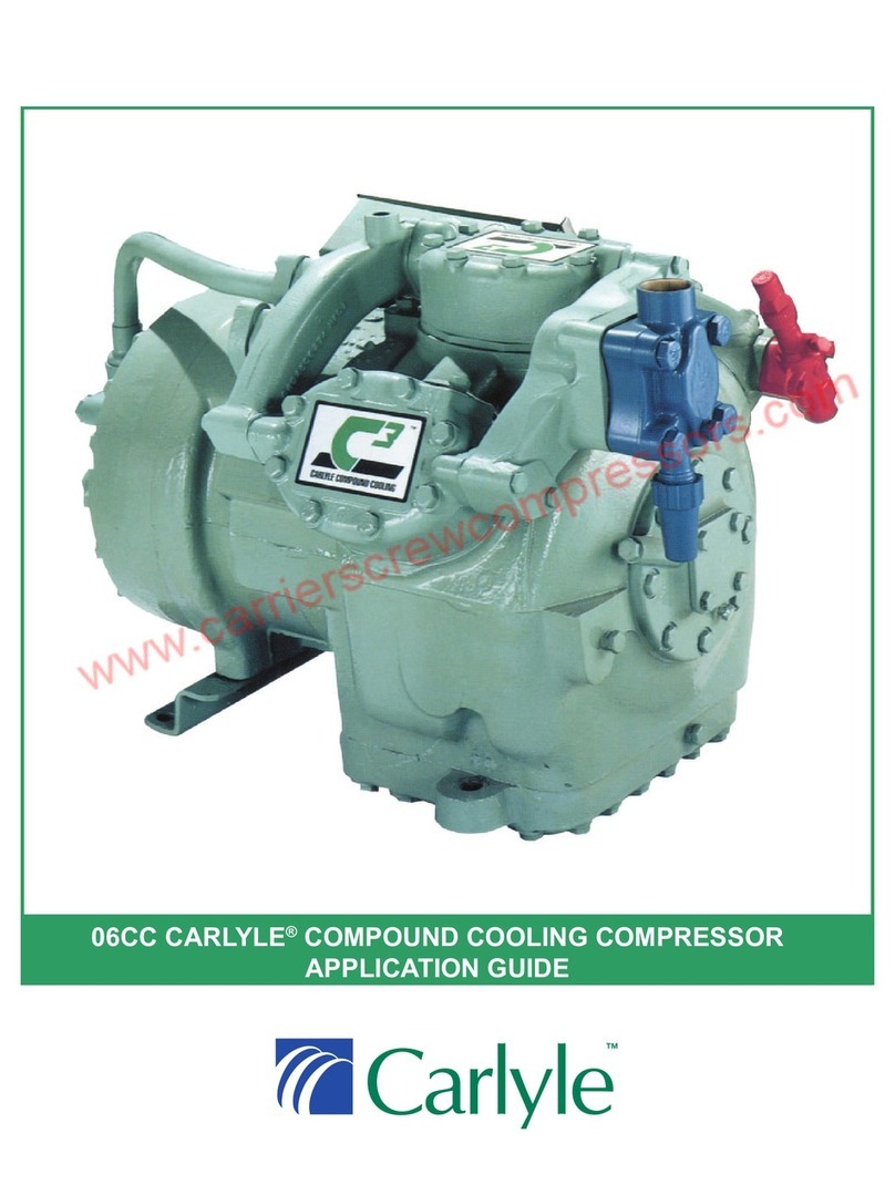
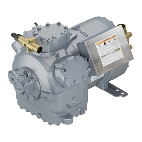
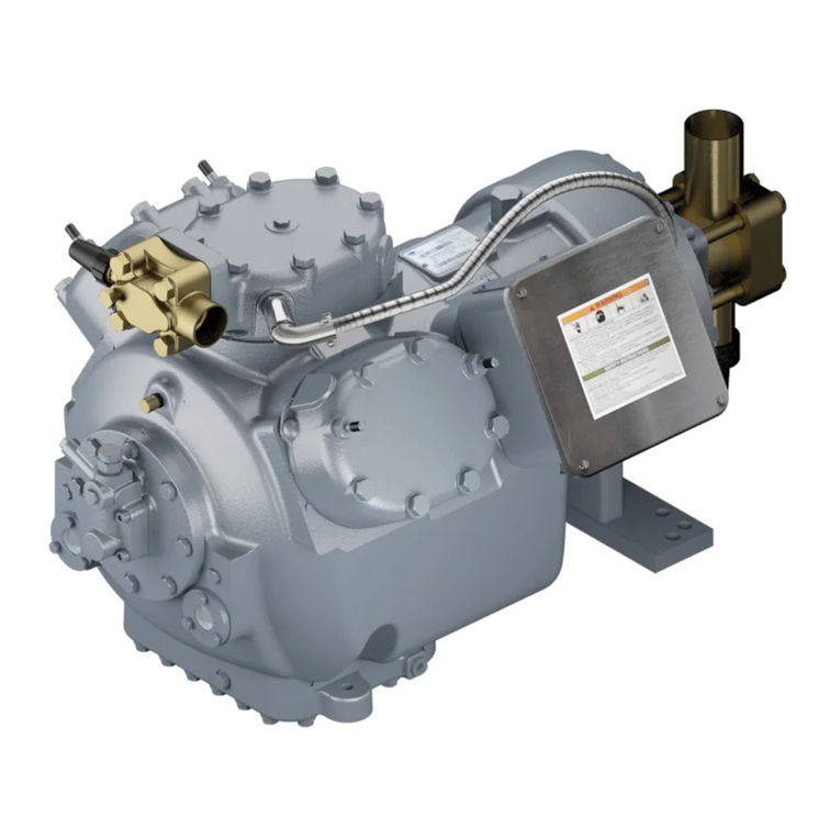
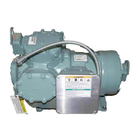
Carlyle 06D User manual

SERVICE GUIDE
06D/06E/06CC
COMPRESSORS
COMPLIMENTS OF:
Carlyle service replacement compressors, parts, and
support are available through a wide distribution
network. /
/iVV>ÃÕ««ÀÌëÀÛ`i`LÞÞÕÀV>
`ÃÌÀLÕÌÀ°
Customer Service Representatives can
provide assistance in locating your nearest distributor.
Rev 2/2017 Lit No: 020-611
USA
800-Go-Carlyle
(800-462-2759)
www.Totaline.com
© Carrier Corporation 2017
Manufacturer reserves the right to discontinue, or change at any time,
ëiVwV>ÌÃÀ`iÃ}ÃÜÌÕÌÌViÀÜÌÕÌVÕÀÀ}L}>Ìð
CANADA
800-668-7905
www.ÜÜ}totaline.c>É
i/LÀ>V
MEXICO
01 800 171 11 11
www.totalinecom.mx/
pages/Sucursales.html

WHAT THIS GUIDE CAN DO FOR YOU
Carlyle Compressor Company provides this guide to aid the service specialist
in proper installation, service, and maintenance of 06D, E, CC compressors.
Following the procedures in this guide will extend the life of the system and
improve performance.
This guide uses the terms DANGER, WARNING and CAUTION. These terms
There is an immediate hazard which WILL result in severe personal
injury or death.
HOW TO USE THIS GUIDE
This book is divided into four major sections (see Table of Contents):
SECTION 1.0 - General Compressor and Customer Information
SECTION 2.0 - Start-Up, Troubleshooting, and Service
SECTION 3.0 - Compressor Parts Data
SECTION 4.0 - Electrical Data
An Index is provided in the back of this guide.
TO GET MORE HELP
Carlyle Compressor Company sells compressors to Carrier for use in their pack-
aged units and to OEMs (Original Equipment Manufacturers) that design and build
the application of our compressor. All questions, on either the packaged system or
(for Carrier systems) or the OEM or its local representative (for other units). If this
support, along with this service guide, cannot resolve your compressor problem,
please contact our Carlyle engineering group.
CARLYLE COMPRESSOR THANKS YOU
FOR SELECTING OUR EQUIPMENT
Hazards or unsafe practices which COULD result in severe personal
injury or death.
Potential hazards or unsafe practices which COULD result in minor
personal injury or equipment damage
CARLYLE COMPRESSOR DIVISION • © CARRIER CORPORATION
P.O. Box 4808 • Syracuse, New York 13221
*OUIF64"(0$"3-:-&
*O$BOBEB88(5PUBMJOF
*O.FYJDP5PUBMJOF
Manufacturer reserves the right
to discontinue, or change at any
time, specifications or designs
and prices without notice and
without incurring obligations.
CAUTION
DANGER
WARNING
have specific meanings that identify the degree of hazard. Typically in the
HVAC industry, these specific meanings are:
finished systems. The system manufacturer is the expert on the system, includingfinished systems. The system manufacturer is the expert on the system, including
the compressor in that system, should be first directed to the local Carrier distributor

1
CONTENTS
1.0 GENERAL COMPRESSOR AND CUSTOMER
INFORMATION
1.1 Compressor Model Number Significance ...................................... 3
1.2 Nameplate Significance.................................................................. 6
1.3 Compressor Serial Number Significance ....................................... 8
1.4 Carlyle OEM Compressor Warranty.............................................. 9
1.5 Service Billing and Credit .............................................................. 9
1.6 Carlyle Service Replacement Compressors, Parts, and Support .. 10
2.0 START-UP, TROUBLESHOOTING, AND SERVICE
2.1 Technical Assistance - Carlyle OEM Compressors ..................... 10
2.2 Recommended Start-Up Procedure .............................................. 11
2.3 Troubleshooting Procedure ........................................................... 20
2.4 Service Procedures ....................................................................... 32
2.5 Connection Points — 06D, 06E, and 06CC Compressors ........... 44
2.6 Cross-Sectional View — 06D Semi-Hermetic Compressor ........ 54
2.7 Cross-Sectional View — 06E Semi-Hermetic Compressor......... 55
2.8 Exploded View — 6-Cylinder 06D Compressor ......................... 56
2.9 Exploded View — 6-Cylinder 06E Compressor.......................... 58
2.10 Torque Guide –– 06D and 06CC (16 to 37 Cfm) Compressors... 60
2.11 Torque Guide –– 06E and 06CC (50 to 99 Cfm) Compressors ... 61
3.0 COMPRESSOR AND PARTS DATA
3.1 06D Series Compressors –– Physical Data .................................. 62
3.2 06E Series Compressors –– Physical Data................................... 64
3.3 06CC Series Compressors –– Physical Data................................ 66
3.4 06D, E High Efficiency (H.E.) Compressors ............................... 68
3.5 Compressor Bodies Without Oil .................................................. 68
3.6 Refrigerants and Oils for 06D, E, CC Compressors..................... 69
3.7 Oil Viscosity and Pour Points ...................................................... 71
3.8 Oil Additives ................................................................................ 72
3.9 Oil Pressure .................................................................................. 72
3.10 High Flow Oil Pump (Bearing Head)........................................... 73
3.11 Replacement Oil Pump/Pump End Bearing Package................... 73
3.12 Oil Pressure Safety Switch ........................................................... 74
3.13 06CC, E Discharge Gas Cylinder Head Temperature Sensor and
06E Pressure Relief Valve............................................................ 84
3.14 06D, E Cylinder Head Cooling Fans............................................ 85
3.15 Capacity Control Accessory Packages ......................................... 86
3.16 Capacity Control Coil Packages (06D, E).................................... 88
3.17 Crankcase Heater Data ................................................................. 89
3.18 Compressor Mounting Data ......................................................... 90
3.19 Compressor Service Valves (06D, E, CC) ................................... 90

2
3.20 Service Valve Gaskets (06D, E, CC) ........................................... 90
3.21 Oil Drain Plug Adapter................................................................. 91
3.22 Sight Glass Adapters for Oil Equalization ................................... 91
3.23 Replacement Sight Glass/Installation Tool .................................. 91
3.24 Replacement Motor End Mounting Foot...................................... 91
3.25 Gaskets –– Cylinder Head and Valve Plate.................................. 92
3.26 Miscellaneous............................................................................... 93
3.27 Valve Plate Packages, Service Replacement................................ 94
3.28 Muffler Recommendations........................................................... 95
3.29 Electrical Accessories................................................................... 96
3.30 Baffle Plate Recommendations .................................................... 97
3.31 Interstage Pressure Tables (06CC Compressors Only) ................ 97
4.0 ELECTRICAL DATA
4.1 06DR 3 Phase Electrical Specifications ..................................... 101
4.2 06DM, DA 3 Phase Electrical Specifications ............................ 103
4.3 06DR, DM Single Phase Electrical Specifications .................... 105
4.4 06ER, EY 3 Phase Electrical Specifications .............................. 106
4.5 06EM, EZ 3 Phase Electrical Specifications.............................. 108
4.6 06EA, ET 3 Phase Electrical Specifications .............................. 110
4.7 06CC (16 to 37 Cfm) 3 Phase Electrical Specifications ............ 112
4.8 06CC (50 to 99 Cfm) 3 Phase Electrical Specifications ............ 114
4.9 06D Electromechanical Overcurrent Protection......................... 115
4.10 06D and 06CC (16-37 Cfm) Electronic Overcurrent
Protection .................................................................................... 116
4.11 Electrical Hook-Up..................................................................... 129
4.12 Voltage and Current Unbalance ................................................. 134
5.0 COMPRESSOR SERVICE WORKSHEETS
06D, 06E COMPRESSOR SERVICE WORKSHEET.............. 136
06CC COMPRESSOR SERVICE WORKSHEET.................... 137
6.0 SMART UNLOADING & PWM VALVE
6.1 Functional Overview .................................................................. 138
6.2 Identification .............................................................................. 139
6.3 Smart Controller Inputs/Outputs ................................................ 140
6.4 Smart Controller Configuration.................................................. 145
6.5 Service Table.............................................................................. 151
6.6 Compressor Protection and Control ........................................... 152
6.7 PWM Valve................................................................................ 153
SERVICE GUIDE INDEX............................................................. 160

3
1.0 — GENERAL COMPRESSOR AND CUSTOMER
INFORMATION
1.1 — Compressor Model Number Significance
}
}
06D COMPRESSORS
06DR 3 37 0 D A 36 5 A – (RP)**
Model = 0, Package = 1 or 9, A = Shipped Without Oil
Oil and Refrigeration (06DR, DM) Unloading Variable:
0 = All Models Except as Noted
5 = No Oil
7 = 1 Unloader Elec. (DR, DM Only)
8 = 2 Unloaders
Electrical Characteristics (XL Start Only, Unless Noted):
New H.E. Models Old Std. Models
31 = 575-3-60 01 = 575-3-60 12 = 208/230-3-60
32 = 208/230-3-60 04 = 200-3-60 13 = 380-3-60
33 = 208/230-1-60 05 = 230-3-60 14 = 200-3-60 (PW)
34 = 220-3-50 06 = 400/460-3-50/60 15 = 230-3-60 (PW)
36 = 400/460-3-50/60 08 = 220-3-50 18 = 220-3-50 (PW)
Electrical Variables:
A = With Internal Thermostat and External Overloads
C = With Internal Thermostat and Without External Overloads
Suction Valve - Variables:
Location, Orientation and Mounting Bolts
Compressor Identification Key:
0 = New Compressor
2 = New Compressor
3 = New Compressor
6 = Service Compressor, Remanufactured
7 = Service Compressor, New Manufactured
8 = New Compressor, Special
9 = Service Compressor, Special
Displacement (in Cfm at 1750 rpm)
Motor Size - (Does Not Signify Horsepower)
Compressor Type:
06DA = Compressor - A/C Duty No Unloading
06DB = Compressor - A/C Duty 1-Step Elec.
06DC = Compressor - A/C Duty 2-Step Elec.
06DD = Compressor - A/C Duty 1-Step Press.
06DE = Compressor - A/C Duty 2-Step Press.
06DF = Compressor - A/C Duty 1-Step Elec.
06DG = Compressor - A/C Duty 2-Step Elec.
06DH = Compressor - A/C Duty 1-Step Press.
06DJ = Compressor - A/C Duty 2-Step Press.
06DM = Compressor Refrig. Duty Medium Temperature
06DR = Compressor Refrig. Duty Low Temperature
06DM = Service Compressor-Replacement for new 06DA, DM without unloading
06DS = Service Compressor-Replacement for new 06DF,G,H and J with
suction cut-off unloading. Compressor has 1-Stage suction
cut-off unloading
06DX = Service Compressor-Replacement for new 06DB,C,D, and E with
hot gas (bypass) unloading. Compressor has 1-stage of bypass unloading
**Refrigeration Partner.
Information in shaded area is no longer available in standard factory production.
Hot Gas
Bypass
Unloading
Suction
Cut-Off
Unloading
Y = Smart Unloading Models
S = Oil Sensor Block and OPSS Sensor
06DK = Compressor - A/C Duty 1-Step Elec. & 2-Step Press.
Suction Cut-Off Unloading Designation for 06DR, DM Compressors:
37 = 380-3-60
Electronic Overcurrent Protection:
0 = None
1 = 115/240V Control Voltage, Electronic Overcurrent Protection
2 = 24V AC Control Voltage, Electronic Overcurrent Protection
3 = 24V DC Control Voltage, Electronic Overcurrent Protection
Electromechanical Overcurrent Protection:
Other manuals for 06D
3
This manual suits for next models
2
Table of contents
Other Carlyle Air Compressor manuals

Carlyle
Carlyle 06D User guide

Carlyle
Carlyle 06D User manual

Carlyle
Carlyle 06ZCE1H3AA06013 User guide

Carlyle
Carlyle 5F Series Manual

Carlyle
Carlyle 06T 033 Series User guide

Carlyle
Carlyle 06CC User guide

Carlyle
Carlyle 06D Instructions and recipes

Carlyle
Carlyle TS Series User guide

Carlyle
Carlyle 06E Instructions and recipes