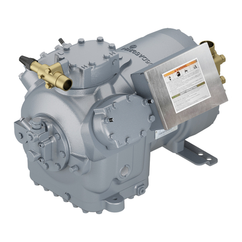
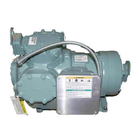
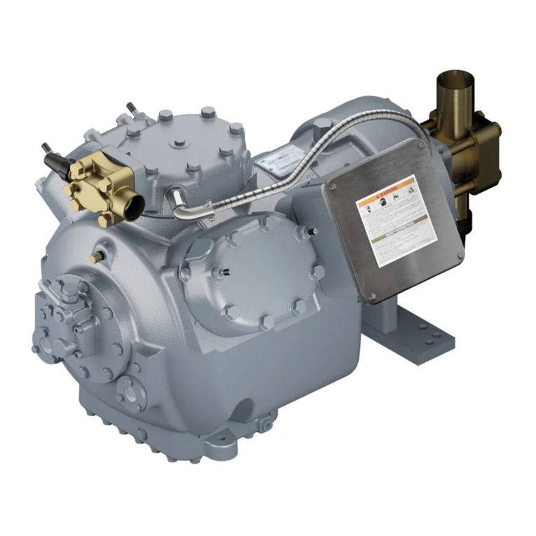
Carlyle TS Series User guide

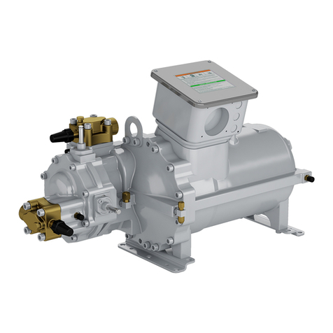
06TS,TT,TU,TV CARLYLE
®
PARAGON TWIN SCREW COMPRESSOR
APPLICATION GUIDE
a06-1663

Introduction
R-134a, R-513A, R-1234ze Applications . . . . . . . . 3
R-404A, R-407A, R-407C, R-407F, R-448A,
R-449A, and R-507A Applications . . . . . . . . . . 3
Scope. . . . . . . . . . . . . . . . . . . . . . . . . . . . . . . . . . . 3
Certifications . . . . . . . . . . . . . . . . . . . . . . . . . . . . . 3
Compressor Offerings . . . . . . . . . . . . . . . . . . . . . . 3
Compressor Displacement (R-134a, R-513A, R-
1234ZE for air and water cooled models) . . . . . . . 3
Compressor Displacement (Low/Medium
Temperature Models). R-404A, R-407A, R-407C,
R-407F, R-448A, R-449A, and R-507A. . . . . . . . . 4
Standard Features . . . . . . . . . . . . . . . . . . . . . . . . . 4
Model Number Significance Chart . . . . . . . . . . . . . 5
Compressor Physical Data and Connections . . . . 6
06TS Compressor . . . . . . . . . . . . . . . . . . . . . . . 6
06TT Compressor . . . . . . . . . . . . . . . . . . . . . . . 7
06TU Compressor . . . . . . . . . . . . . . . . . . . . . . . 8
06TV Compressor . . . . . . . . . . . . . . . . . . . . . . . 9
1.0 Medium/High Temperature
System Design Considerations
1.1 Refrigerants and Lubricants. . . . . . . . . . . . . . 10
1.2 Environmental Considerations . . . . . . . . . . . . 10
1.3 Operating Limits and Controls . . . . . . . . . . . . 10
1.4 Control Points Summary . . . . . . . . . . . . . . . . 14
2.0 Medium/High Temperature
System Oil Management
2.1 Oil Pressure Requirements . . . . . . . . . . . . . . 15
2.2 Oil Separator Recommendations. . . . . . . . . . 15
2.3 Oil Heater Recommendations for Air-Cooled
Models . . . . . . . . . . . . . . . . . . . . . . . . . . . . . . 15
2.4 Oil Level Safety Switch . . . . . . . . . . . . . . . . . 16
2.5 Oil Filter . . . . . . . . . . . . . . . . . . . . . . . . . . . . . 16
3.0 Low Temperature
System Design Considerations
3.1 Refrigerants and Lubricants. . . . . . . . . . . . . . 17
3.2 Environmental Considerations . . . . . . . . . . . . 17
3.3 Operating Limits and Controls . . . . . . . . . . . . 17
3.4 Control Points Summary . . . . . . . . . . . . . . . . 22
4.0 Low Temperature
System Oil Management
4.1 Oil Pressure Requirements . . . . . . . . . . . . . . 23
4.2 Oil Separator Recommendations . . . . . . . . . .24
4.3 Oil Heater Recommendations. . . . . . . . . . . . .23
4.4 Oil Level Safety Switch . . . . . . . . . . . . . . . . . .23
4.5 Oil Filter . . . . . . . . . . . . . . . . . . . . . . . . . . . . .24
4.6 Oil Cooling Systems . . . . . . . . . . . . . . . . . . . .24
4.7 Oil Cooler Selection . . . . . . . . . . . . . . . . . . . .24
4.8 Oil Cooler Sizing . . . . . . . . . . . . . . . . . . . . . . .25
5.0 Unloader Operation
5.1 Unloader System Control Points. . . . . . . . . . .27
5.2 Approximate Part Load Factors . . . . . . . . . . .28
6.0 Software Version 2.0 Schematics
6.1 Compressor Requirements. . . . . . . . . . . . . . .36
6.2 Design Pressures . . . . . . . . . . . . . . . . . . . . . .36
7.0 Variable Frequency Drive
Guidelines
7.1 Scope . . . . . . . . . . . . . . . . . . . . . . . . . . . . . . .37
7.2 Capacity Control . . . . . . . . . . . . . . . . . . . . . . .37
7.3 Power Supply . . . . . . . . . . . . . . . . . . . . . . . . .37
8.0 Compressor Electrical Data
8.1 Allowable Voltage Range . . . . . . . . . . . . . . . .39
8.2 Electrical Connection Requirements. . . . . . . .39
8.3 Motor Data . . . . . . . . . . . . . . . . . . . . . . . . . . .41
9.0 Compressor Accessories
9.1 Oil Separators. . . . . . . . . . . . . . . . . . . . . . . . .48
9.2 Vertical Oil Separator Kit . . . . . . . . . . . . . . . .49
9.3 Horizontal Oil Separator Kit . . . . . . . . . . . . . .49
9.4 Compressor Components Kit . . . . . . . . . . . . .49
9.5 Compressor Protection and Slide Valve
Capacity Control Kits . . . . . . . . . . . . . . . . . . .50
9.6 Service Valves . . . . . . . . . . . . . . . . . . . . . . . .50
9.7 Motor Protection Devices . . . . . . . . . . . . . . . .50
9.8 Oil Coolers . . . . . . . . . . . . . . . . . . . . . . . . . . .51
10.0 Packaging and Storage
Requirements
10.1 Packaging . . . . . . . . . . . . . . . . . . . . . . . . . . .52
10.2 Shipping . . . . . . . . . . . . . . . . . . . . . . . . . . . .52
10.3 Storage . . . . . . . . . . . . . . . . . . . . . . . . . . . . .52
10.4 Weights and Dimensions . . . . . . . . . . . . . . .52
Contents

3
This manual is for the Carlyle®Paragon screw compres-
sor product line, which is comprised of four unique com-
pressor families (series type TS, TT, TU, and TV). Carlyle
offers distinct versions of the Paragon Twin-Screw Com-
pressors for Low/Medium/High Temperature applications.
The operational limits, required accessories, and opera-
tional guidelines are contained in this manual and must
be complied with to stay within the compressor warranty
guidelines.
R-134a, R-513A, R-1234ze Applications
The TS series compressors are designed for air-cooled
applications only. The TT, TU, and TV series compres-
sors are available in both air-cooled and water-cooled
applications. There are 3 different displacement sizes of
each of the TS, TT, and TV series compressors, along
with 2 displacement sizes of the TU series compressor.
Each Paragon twin-screw compressor is designed to be
applied with a dedicated, performance-matched oil sep-
arator. Carlyle offers two types of oil separators: high-effi-
ciency (for applications in flooded-type systems) and
standard-efficiency (for application in direct expansion-
type systems). This compressor / oil separator assembly
is then applied in a single-compressor, medium-tempera-
ture, or high-temperature refrigeration circuit. Carlyle
offers the required oil separators as shown in Section 9.1
of this application guide. See Section 10.5 of this docu-
ment for Assembly views of the R-134a Paragon models
applied with these oil separator designs. Application
guidelines for the R-134a compressors that have been
approved for VFD applications are covered in this guide.
R-404A, R-407A, R-407C, R-407F, R-448A,
R-449A, and R-507A Applications
The low/medium temperature Paragon twin-screw com-
pressor models are designed to be applied in single or
multiple compressor circuits. Each circuit requires a prop-
erly selected oil separator (contact Carlyle Application
Engineering for selection criteria). Carlyle offers 3 models
within each of the TS and TT compressor series for low/
medium temperature applications.
Scope
This application guide is intended to familiarize system
designers with the Paragon screw compressor and to
provide technical information necessary to assure safe
and reliable compressor operation.
Certifications
UL and CSA approvals have been obtained for specific
06TS, 06TT, 06TU, and 06TV screw compressor models
applied with R-134a and for certain 06TS and 06TT
screw compressor models applied with R-404A, R-407A,
R-407C, R-407F, and R-507A (compressors that have an
R or M in the fifth digit of the model number).
UL File #: SA4936 CSA File #: SA4936
For the UL and CSA approvals it is essential that only
Listed, Special-Purpose circuit breakers or Carlyle
approved, solid-state motor overloads be used (contact
Carlyle Application Engineering for further information).
For circuit breakers, the Must Trip Amp settings must not
exceed 140% of the compressor rated load amps.
Both UL and CSA approvals have been obtained for all
voltage combinations shown in Section 8.3 of this guide.
These compressor models also comply with the EC Low
Voltage and Machinery Directives.
Compressor Offerings
The four Paragon compressor frame sizes (TS, TT, TU,
and TV) are optimized for application in economized
refrigeration circuits. Non-economized capacity will
decrease by 11 to 16% for water-cooled operation. The
following tables show the displacements for each of the
compressors at 60 Hz.
Compressor Displacement (R-134a, R-513A,
R-1234ze for air and water cooled models)
See Tables 1 and 2.
Table 1 — Air-Cooled Models
Table 2 — Water-Cooled Models
NOTE: Carlyle has optimized the Vi (volume index) for
the R-134a air-cooled and water-cooled models.
MODEL
NUMBER
NOMINAL
HORSEPOWER
DISPLACEMENT
(CFM at 60 Hz)
06TSA137 60 137
06TSA155 75 155
06TSA186 75 186
06TTA266 120 266
06TTA301 150 301
06TTA356 150 356
06TUA483 225 483
06TUA554 225 554
06TVA680 340 680
06TVA753 340 753
06TVA819 340 819
MODEL
NUMBER
NOMINAL
HORSEPOWER
DISPLACEMENT
(CFM at 60 Hz)
06TTW266 90 266
06TTW301 90 301
06TTW356 120 356
06TUW483 160 483
06TUW554 160 554
06TVW680 225 680
06TVW753 225 753
06TVW819 225 819
Introduction
4
Compressor Displacement (Low/Medium
Temperature Models). R-404A, R-407A, R-407C,
R-407F, R-448A, R-449A, and R-507A
See Tables 3 and 4.
Table 3 — Low Temperature (Refrigeration) Models
Table 4 — Medium Temperature Models
Standard Features
See Fig. 1-4 for physical data and connection information.
Discharge Check Valve
The discharge check valve is an axial movement type
located within the compressor. The check valve i s field ser-
viceable by removing the oil separator or discharge line to
access the valve in the compressor discharge housing.
Pressure Relief Valve
The Paragon screw compressors have an internal relief
device which is designed to relieve pressure from the
high side to the low side of the compressor.
Suction and Economizer Screens
To increase the reliability of the compressor, a screen has
been incorporated as a standard feature into the suction
inlet and economizer inlet of the compressor. The suction
inlet screen is installed into the suction inlet of each com-
pressor. The economizer inlet screen is supplied in the
economizer flange package (which is included in the
compressor kit 06TT660093). Refer to the economizer
flange Installation Instruction document for more details.
Slide Valve Unloading System
All Paragon screw compressors utilize a continuous slide
valve unloading system. The slide valve decreases the
compressor's capacity by reducing the amount of com-
pression performed by the screw rotors. It is infinitely
variable down to approximately 30% of full load capacity
for air-cooled models and approximately 15% of the full
load capacity for water-cooled models. These percent-
ages of unloading are based on operation at typical rating
conditions and may be different at other operating condi-
tions.
Variable Speed for Capacity Control
The paragon compressor has been qualified to operate
with a variable frequency drive (VFD) for all low, medium,
and high temperature applications. The VFD speed appli-
cation range is 30 to 60 Hz. The compressor slide valve
should remain in the fully loaded position while the VFD
is controlling compressor capacity between 30 to 60 Hz.
The slide valve may be used to reduce compressor
capacity below 50% (30 Hz) if required. Recommenda-
tions and requirements for these applications are pro-
vided in Section 7.0.
MODEL
NUMBER
NOMINAL
HORSEPOWER
DISPLACEMENT
(CFM at 60 Hz)
06TSR137 60 137
06TSR155 75 155
06TSR186 75 186
06TTR266 120 266
06TTR301 150 301
06TTR356 150 356
MODEL
NUMBER
NOMINAL
HORSEPOWER
DISPLACEMENT
(CFM at 60 Hz)
06TSM137 75 137
06TSM155 75 155
06TTM266 150 266
06TTM301 150 301

5
Model Number Significance Chart
123456789101112
06TT
A
356SS1C
12th
1st & 2nd A
06 B
C
D
3rd & 4th
TS
TT 11th
TU 1
TV 3
5th
10th MOTOR SIZE
A
R
W
1ST
TS2
TS3
TT1
TT2
TT3
9th
S
2UT
T
3UT
W
1VT
X
2VT
Z
3VT
Air Cooled Vi
819
6th, 7th & 8th
DISPLACEMENT
(CFM at 60 Hz)
137
155
MODEL
REF.
483
554
680
753
266
301
356
186
DIGIT
MODEL NO.
DESIGN FEATURE
Semi-Hermetic
MODEL CODE
Phase 1
Product Variant
400/460-3-50/60
Paragon
PACKAGE / ACCS.
Not Used
Not Used
Plate Mounting Feet
Bar Mounting Feet
DESIGN LEVEL
Refrigeration Vi
Water-Cooled Vi
Paragon
Paragon
Paragon
DESIGN VARIABLE
575-3-60
380-3-60
200/230-3-50/60
200-3-60
MOTOR VOLTAGES
690-3-50 (Wye)
690-3-60 (Wye)
LEGEND
Vi — Volume Index
WC — Water-Cooled
VFD — Variable Frequency Drive
X Variable-Speed (WC Vi)
60
75
90
120
150
160
225
340
G
J
M
P
S
T
W
X
9 Not Used
M Medium Temperature Vi

6
Compressor Physical Data and Connections
Fig. 1 — 06TS Compressor Physical Data and Connections

7
Compressor Physical Data and Connections (cont)
Fig. 2 — 06TT Compressor Physical Data and Connections
Z

8
Compressor Physical Data and Connections (cont)
Fig. 3 — 06TU Compressor Physical Data and Connections
a06-1666

9
Compressor Physical Data and Connections (cont)
Fig. 4 — 6TV Compressor Physical Data and Connections
a06-1686
DISCHARGE FLANGE OIL SUPPLY TO
CAPACITY CONTROL
3/8 ORIFICE
SUCTION TEMP WELL
1/4 INCH SAE
SUCTION FLANGE
OIL PRESSURE PORT
3/8 INCH SAE ECONOMIZER FLANGE
OIL INLET PORT
5/8 ORIFICE
LIFTING
LOCATIONS
HIGH SIDE
TEMP WELL
1/4 INCH SAE
HIGH SIDE
PRESSURE PORTS
1/4 INCH SAE
CAPACITY CONTROL SOLENOIDS
ECONOMIZER PORT
1 5/8 INCH ODS
SUCTION CONNECTION
6 INCH CLASS 150 FLANGE
Ø24 LIFTING HOLE
OIL INJECTION PORT
1/4 INCH SAE
Ø24 LIFTING HOLE
DISCHARGE CONNECTION
5 INCH CLASS 150 FLANGE
SUCTION
OIL DRAIN PORT
3/8 INCH SAE
CAPACITY CONTROL OIL
SUPPLY PORT 3/8 ORIFICE
OIL DRAIN PORT
1/4 SAE

10
1.1 Refrigerants and Lubricants
Approved Refrigerants
The Paragon medium-temperature screw compressor is
specifically designed for use in R-134a systems.
Approved Lubricants
The Paragon screw compressor is approved for use with
the following lubricants:
Approved Lubricant — Emkarate RL 220H
Viscosity Grade — ISO 220
or
Approved Lubricant — Emkarate RL 220HC
Viscosity Grade — ISO 220
Carrier Part Number — 1 gallon: P903-2301
5 gallon: P903-2305
Assembly Grease
On occasion, it may be necessary to use an assembly
grease to retain an o-ring within its groove. The following
assembly grease is approved for use with the Paragon
screw compressor:
Approved Lubricant — Castrol Synplex GP2
or
Approved Lubricant — Parker Super-O-Lube
Carrier Part Number — 19XL680001
Terminal Pin Dielectric Grease
Carlyle recommends that compressor motor terminal
pins are coated with dielectric grease (P/N 06TT660050)
to reduce the effects of condensation that may form on
the terminal pins.
1.2 Environmental Considerations
Operating Ambient Temperature
The screw compressor is designed for the following ambi-
ent temperature ranges:
Non-Operating: -40°F to 176°F (-40°C to 80°C)
Operating: -31°F to 131°F (-35°C to 55°C)
Salt-Spray Requirements
The compressor has been tested through 500 hours of
salt-spray in compliance with ASTM specification B-117.
1.3 Operating Limits and Controls
R-134a, R-513A, R-1234ze Operating Envelope
The following operating envelopes show where the com-
pressor can be operated in both direct expansion and
flooded applications. See Fig. 5-7. The envelopes differ
for the unique design configuration of the compressor.
The fifth digit of the model number indicates the operat-
ing envelope. The load line percentages refer to the
capacity relative to full load at the same saturated suction
temperature (SST) and saturated discharge temperature
(SDT).
1.0 Medium/High Temperature System Design
Considerations (R-134a, R-513A, R-1234ze)

11
Fig. 5 — Operating Limits for Full Load Operation
Paragon Operating Envelopes on R-134a, R-513A
40
50
60
70
80
90
100
110
120
130
140
150
160
170
-20-100 10203040506070
Saturated Suction Temperature (ºF)
SDT (ºF)
4
14
24
34
44
54
64
74
-29 -24 -19 -14 -9 -4 1 6 11 16 21
Saturated Suction Temperature (ºC)
SDT (ºC)
W/C Envelope
TS3 A/C Ma x
SDT
TS1 & TS2 A/C
Max SD T
A/C Envelope
LEGEND
A/C — Air-Cooled
W/C — Water-Cooled
Fig. 6 — Operating Limits for Full Load Operation

12
Start-Up and Suction Pressure Transients
Operating a screw compressor without refrigerant flow
through the compressor can be harmful. When this
occurs, the evaporator typically will go into a vacuum,
leading to very high pressure ratios and little mass flow to
carry the heat away from the screw rotors. This situation
most often occurs during start-up when the refrigerant
may be in another part of the system. This is tolerable for
short periods of time. The Paragon screw compressor
should not be allowed to operate with a suction pressure
less than 0 psig (vacuum) for more than 1 minute after a
“cold” start. (Contact Carlyle Application Engineering for
more information on cold starts.) If a compressor is
allowed to operate for longer periods of time without
refrigerant flow, catastrophic damage to the screw rotors,
rotor housing, and discharge housing may occur, requir-
ing compressor replacement.
Air-Cooled Oil Supply at Compressor
To reduce the possibility of liquid refrigerant becoming
entrained in the oil, it is recommended that the tempera-
ture of the oil entering the compressor is kept above the
outdoor ambient as shown in Fig. 8.
Temperature Limits
Table 5 shows the temperature range of control points
allowable for the compressor using the approved lubri-
cants listed in Section 1.1, Refrigerants and Lubricants.
Paragon Operating Envelopes on R-134a, R-513A
UNL (A/C )
UNL (W/C)
50%
75%
40
50
60
70
80
90
100
110
120
130
140
150
160
170
-20-100 10203040506070
Saturated Suction Temperature (ºF)
SDT (ºF)
4
14
24
34
44
54
64
74
-29 -24 -19 -14 -9 -4 1 6 11 16 21
Saturated Suction Temperature (ºC)
SDT (ºC)
FULL UNLOAD
LIMIT FOR A/C
FULL UNLOAD
LIMIT FOR W/C
50% LOAD LIMIT
75% LOAD LIMIT
W/C Envelope
A/C Envelope
LEGEND
A/C — Air-Cooled
W/C — Water-Cooled
Fig. 7 — Operating Limits for Unloaded Operation
NOTE: Liquid injection may be required when operating fully unloaded. Contact Carlyle Applications Engineering for valve sizing requirements.
0
5
10
15
20
25
020406080100
Outdoor Ambient Temperature [OAT] (ºF)
Min Delta Oil Temp
>
Ambient (ºF)
0
2
4
6
8
10
12
14
-18 -7 4 16 27 38
Outdoor Ambient Temperature [OAT] (ºC)
Min Delta Oil Temp >Ambient (ºC)
Fig. 8 — Oil Temperature
a06-1669

13
Table 5 — Allowable Temperature Ranges
Compressor Rotation Control
Correct compressor rotation is one of the most critical
application considerations. Powered reverse rotation,
even for a very short duration, can seriously affect the
reliability of the compressor.
The reverse rotation protection scheme must be
capable of determining the direction of rotation and
stopping the compressor within 1 second.
Reverse rotation is most likely to occur at initial start-up
or whenever the wiring to the compressor terminals is
disturbed.
To minimize the possibility for reverse rotation operation,
Carlyle recommends the following procedures:
1. During initial run test of the unit, a suitable low-
pressure switch should be temporarily installed on
the high-pressure port of the compressor and be
wired to open the compressor control circuit. The
purpose of this switch is to protect the compressor
against any wiring errors at the compressor terminal
pins. The electrical contacts of the switch must be
wired in the control circuit of the compressor start
components to shut off the compressor in the event it
is operating in reverse rotation. This switch would
remain in place for the duration of the run test. At the
end of the run test the switch would be removed so
that it could be used on the next unit or compressor
to be tested.
2. For service replacement compressors, a similar pro-
tection system is recommended. The unit service lit-
erature will make reference to this switch and provide
instructions on how to temporarily install the low-
pressure switch into the safety circuit for the com-
pressor. Each service compressor will be supplied
with Installation Instructions documenting the proce-
dure for installing and using the switch. The switch
will remain in place until the compressor has been
started and direction of rotation has been verified; at
this point the switch will be removed.
The low-pressure switch must be suitable for the pres-
sures consistent with R-134a systems, and the switch
must be manually resettable and open when the pressure
falls below 50 mm (2 inches) of vacuum. The switch is a
manual reset type that can be reset after the pressure
has once again risen above 1.7 bar (25 psia). It is critical
that the switch be a manual reset type to preclude the
compressor from short cycling in the reverse direction.
If a switch is not available, a manifold gage connected to
the discharge housing of the compressor BEFORE THE
DISCHARGE CHECK VALVE can be used. If the com-
pressor can be “bumped” or “jogged” very quickly (< 1
second) while someone is watching the gage, compres-
sor rotation can be determined without damage to the
compressor. If the pressure drops, the compressor is
rotating backwards and will have to be rewired. If the
pressure goes up, the compressor is spinning in the cor-
rect direction.
Refrigeration System Design Cons iderations
In order to eliminate the possibility of refrigerant migrat-
ing into the oil separator and compressor, Carlyle
requires the application of a positive-seal, discharge
check valve (or a similar functioning device) to be
installed in the discharge line after the oil separator.
Carlyle recommends the application of our qualified
Safety Control Module package (P/N 6BSB000472)
which provides the following safety control functionality:
• Discharge Temperature Monitoring
• Oil Level Monitoring (Optional)
• Reverse Rotation Monitoring
• Oil Flow-Rate/Supply Monitoring
Technical documentation for this Safety Control Module
package (P/N 6BSB000472) is provided on the Carlyle
Website at www.carlylecompressor.com
CONTROL
POINT MINIMUM MAXIMUM
Discharge
Gas
20°F (11°C)
superheat 210°F (99°C)
Economizer
Gas
Saturated
Liquid
9°F (5°C)
superheat
Suction
Gas
Saturated
Vapor
Can float if motor
and discharge
maximum temps
are met
Oil Supply at
Compressor Refer to Fig. 8 210°F (99°C)
Motor
Windings No limit 275°F (135°C)

14
1.4 Control Points Summary
NOTE: Carlyle offers Compressor Protection Module package, P/N 6BSB000472, which protects against reverse rotation, low oil flow and maximum
discharge gas temperature. See Marketing Bulletin 14M-01 at www.carlylecompressor.com.
Reverse Rotation / Operation with Suction Pressure in Vacuum
• Control must detect and prevent reverse rotation of the compressor within 1 second of compressor start-up.
• Compressor must not operate in a vacuum, as measured at the suction pressure port, for greater than 1 minute.
Oil Pressure Confirmation / Safety
• Three pressures must be observed to ensure that the oil pressure is suitable for compressor operation: suction, discharge and oil.
• Oil pressure safety control must be manually reset.
• Oil pressure must be maintained as follows:
1. POIL > [0.7 x (PDISCHARGE –PSUCTION) + PSUCTION]
2. POIL > [PSUCTION +0.5 bar] 15 seconds after start
(Air-Cooled models; Ain 5th digit of model numbers)
[PSUCTION + 1.0 bar] 45 seconds after start
(Refrigeration models; Rin 5th digit of model numbers)
[PSUCTION + 1.0 bar] 75 seconds after start
(Water-Cooled models: Win 5th digit of model numbers)
Oil Supply Confirmation / Oil Level Switch
• Oil supply to the compressor must be maintained during operation at all times.
• Compressor operation must be stopped if the required oil level switch is open for 5 continuous seconds.
• Oil supply solenoid valve must be closed during OFF cycles.
Oil Filter Differential Pressure
• Compressor operation must be stopped if the pressure differential measured between the entering and leaving oil filter locations exceeds
2 bars.
• The oil filter supply tubing design should apply valves to allow for the isolation and replacement of the filter without removing the system refrig-
erant charge.
Motor Temperature Limitation
• Motor temperatures must be continuously monitored during compressor operation.
• Motor temperatures must not exceed 275°F (135°C).
Compressor Short Cycling
• Control must provide for a minimum of 10 minutes time delay before restarting the Paragon compressor.
• The maximum number of compressor START cycles per hour is 6.
Maximum Discharge Gas Temperature
• Discharge gas temperatures must not exceed 210°F (99°C).
• Control must prevent compressor operation when discharge gas temperatures exceed this maximum.
Maximum Oil Temperature
• Oil temperatures must not exceed 210°F (99°C).
• Control must prevent compressor operation when oil temperatures exceed this maximum.
Run-Proof
• Current must be monitored to detect welded contacts on a contactor or single-phase condition.
• Oil flow must be resumed if a contactor is determined to be welded shut.
• Compressor must be shut down if a single-phase condition is detected.
Liquid Line Solenoid / Economizer
• A liquid line solenoid valve is required to shut off liquid flow to the compressor during OFF cycles.
• Controlling this valve allows for additional capacity reduction during low load conditions.
Unloading Control
• Control must be provided to the two unloader coils. These coils position the slide valve mechanism within the compressor and allow for infinite
unloading valve positioning.
Unloaded Shutdown
• It is recommended that the compressor operate for 30 seconds fully unloaded prior to shut down.
This ensures fully unloaded re-start will occur.

15
Oil supply system components are shown in Fig. 9.
2.1 Oil Pressure Requirements
System pressure is used to generate the oil pressure
required to lubricate bearings and provide the oil that
acts as a seal between the screw rotors and the bores.
Oil pressure is monitored continuously during compres-
sor operation. The oil pressure must meet the following
criteria, based on PDISCHARGE, PSUCTION and POIL:
1. POIL > [0.7 x (PDISCHARGE –PSUCTION) + PSUCTION]
2. POIL > [PSUCTION +0.5 bar] 15 seconds after start
[PSUCTION +1.0 bar] 45 seconds after start
(Air-Cooled models; Ain fifth digit of model number)
[PSUCTION +1.0 bar] 75 seconds after start
(Water-cooled models; Win 5th digit of model number)
The unit control system must monitor the oil pressure dif-
ferential, as well as the operating condition, so the com-
pressor can be shut down if the minimum requirements
are not met for any duration exceeding 15 seconds.
This time delay has two functions: first, to avoid nuisance
tripping during normal and transient operation, and sec-
ond, to allow the system sufficient time to develop pres-
sure differential during start-up.
The compressor must be shut down and prevented from
restarting when the low oil pressure safety is tripped. The
safety should be a manual reset type that locks out com-
pressor operation until the system is serviced.
Carlyle offers a Compressor Protection Module package
to provide protection against loss of oil flow, reverse-rota-
tion and elevated discharge gas temperature.
2.2 Oil Separator Recommendations
The Paragon compressor requires an oil separator. The
combined oil capacity of the oil separator sump, the oil
reservoir, and the oil cooler, should be greater than the
values shown in Table 6.
The separator should be selected to provide a maximum
oil carryover leaving the separator required by that sys-
tem/application. Approximate oil flow versus compressor
pressure differential (Discharge Pressure - Suction Pres-
sure) is shown in Fig. 10. Additional oil charge may be
required for systems that have longer tubing sets. See
Sections 9.1.1, 9.1.2, and 10.5 for additional information.
2.3 Oil Heater Recommendations for
Air-Cooled Models
For the typical oil separators used with the Paragon com-
pressor (see Table 6), a 500-watt flexible strip heater is
recommended. The heater should be wired to operate
when the compressor is OFF. This minimizes the migra-
tion of refrigerant to the oil stored in the sump. Figure 8
shows the minimum oil temperatures that must be main-
tained when the compressor is not operating based on
the outdoor ambient temperature (OAT). If the application
will allow refrigerant to collect in the compressor, then a
heater must be installed on the compressor. Running unit
water that is at least 20°F (11°C) below OAT, if possible,
can be used to prevent refrigerant from collecting in the
compressor. Carlyle recommends that the oil tempera-
ture be monitored in warm climate applications and that
the oil separator heater be cycled off if oil temperatures
reach 190°F (88°C).
OIL
FILTER
OIL
SOLENOID
VALVE
CHECK
VALVE
OIL
SEPARATOR
HEATER
(BOTTOM)
OIL
LEVEL
SWITCH
(BOTTOM)
OIL
SHUTOFF
VALVE
Fig. 9 — Oil Supply System Components
a06-1685
Fig. 10 — Oil Supply at Compressor
0
1
2
3
4
5
6
0 50 100 150 200 250 300
Discharge - Sucon Pressure (PSID)
Typical Oil Flow Rate (GPM)
A/C, W/C
LEGEND
A/C — Air-Cooled
W/C — Water-Cooled
2.0 Medium/High Temperature System Oil Management
(R-134a, R-513A, R-1234ze)

16
Table 6 — Oil Separators
2.4 Oil Level Safety Switch
An oil level safety switch must be installed in the sump of
the oil separator or the oil reservoir, depending on the
system design. Carlyle recommends an oil level safety
switch that interrupts compressor operation if oil levels
are below adequate levels. Enough oil should remain in
the sump when the switch is opened for the compressor
to operate for at least one minute before completely run-
ning out of oil.
To reduce the possibility of false oil level alarms, Carlyle
recommends that the oil level safety switch should be
open continuously for 5 seconds prior to initiating com-
pressor shutdown.
2.5 Oil Filter
Provisions should be made to isolate the oil filter using
some combination of shutoff valves and/or check valves.
This will allow for the filter element to be replaced without
removing or isolating the charge in the unit.
Because of the long bearing life requirements, filtration
for this compressor is very stringent. The Beta Ratio for
this filter is greater than or equal to 200 for a five micron
particle size evaluated using ISO 16889 ((5)200).
Filter areas must also be sufficient to avoid premature
clogging of the filter during normal operation. The Carlyle
supplied filters have a filtration area of > 5000 cm2. An
alarm in the controls should be signaled any time the
pressure drop across the filter (PDISCHARGE –POIL)
exceeds 2 bar (29 psid) indicating the filter needs to be
replaced.
PART NUMBER MINIMUM OIL CHARGE DISCHARGE CFM
SIDE-MOUNT HORIZONTAL
OIL SEPARATORS
8BSB000704 4.5 gal. (17.0 L) 17-150
8BTB000705 4.5 gal. (17.0 L) 17-170
8BVB000787 4.5 gal. (17.0 L) 15-150
COMPACT OVER / UNDER OIL
SEPARATORS
8BSB000643 4.5 gal. (17.0 L) 17-170
8BTB000644 4.5 gal. (17.0 L) 17-170
VERTICAL OIL SEPARATORS KH31ZZ212 10.0 gal. (38.0 L) 30-60

17
3.1 Refrigerants and Lubricants
Approved Refrigerants
The Paragon low/medium temperature duty screw com-
pressor is specifically designed for use in single or paral-
lel compressor systems.
Approved Lubricants
The Paragon screw compressor is approved for use with
the following lubricants:
Approved Lubricant - Solest 170
Viscosity Grade - ISO 170
Assembly Grease
On occasion, it may be necessary to use an assembly
grease to retain an o-ring within its groove. The following
assembly grease is approved for use with the Paragon
screw compressor:
Approved Grease - Castrol Synplex GP2
Or
Approved Grease - Parker Super-O-Lube
Carrier Part Number - 19XL680001
Terminal Pin Dielectric Grease
Carlyle recommends that compressor motor terminal
pins are coated with dielectric grease, P/N 06TT660050,
to reduce the effects of condensation which may form on
the terminal pins.
3.2 Environmental Considerations
Operating Ambient Temperature
The screw compressor is designed for the following ambi-
ent temperature ranges:
Non-Operating: -40°F to 176°F (-40°C to 80°C)
Operating: -31°F to 131°F (-35°C to 55°C)
Salt-Spray Requirements
The compressor has been tested through 500 hours of
salt-spray in compliance with ASTM specification B-117.
3.3 Operating Limits and Controls
Low and Medium Temperature Operating
Envelopes
The following low and medium temperature operating
envelopes show where the compressor can be operated
in both water-cooled and air-cooled direct expansion
applications. See Fig. 11 and 12.
The Motor Cooling and Discharge Gas De-Superheating
lines are added to the envelopes to provide guidance for
OEM customers.
3.0 Low/Medium Temperature System Design Considerations
(R-404A, R-407A, R-407C, R-407F, R-507A, R-448A, R-449A)

18
Fig. 11 — Paragon Low Temperature Operating Envelope
Saturated Discharge Temperature (ºF)
150
140
130
120
110
100
Rang Point
90
80
70
60
50
-45° F
40
Liquid Injecon Mass Flow < 30% Sucon Mass Flow
R-404A / R-507A Envelope
Rang Point (-25 / 105)
50% Load Line
Unloaded
Motor Cooling Required in this Region
Saturated Sucon Temperature Limit of
R-407A, R407C, R407F, R448A, R449A
-60 -50 -40 -30 -20 -10 0 10
Saturated Suction Temperature (ºF)
Fig. 12 — Paragon Medium Temperature Operating Envelope
SaturatedDischarge Temperature (°F)
140
130
120
110
100
90
80
06TSM137 & All Models
70 06TSM155 Limit Line
06TTM266 Limit Line
60
06TTM301 Limit Line
50
40
-30 -20 -10 0 10 20 30 40 50 60 70
Saturated Suction Temperature (°F)

19
Start-Up and Suction Pressure Transients
Operating a screw compressor without refrigerant flow
through the compressor can be harmful. When this
occurs, the evaporator typically will go into a vacuum,
leading to very high pressure ratios and little mass flow to
carry the heat away from the screw rotors. This situation
most often occurs during start-up when the refrigerant
may be in another part of the system. This is tolerable for
short periods of time. The Paragon screw compressor
should not be allowed to operate with a suction pressure
less than 0 psig (vacuum) for more than 1 minute after a
“cold” start. (Contact Carlyle Application Engineering for
more information on cold starts.)
If a compressor is allowed to operate for longer periods of
time without refrigerant flow, catastrophic damage may
occur to the screw rotors, rotor housing, and discharge
housing, requiring compressor replacement.
Oil Supply at Compressor
To reduce the possibility of liquid refrigerant becoming
entrained in the oil during an OFF cycle, it is recom-
mended that the temperature of the oil entering the com-
pressor is kept above the outdoor ambient as shown in
Fig. 13. See Section 4.0 for additional information.
Allowable Temperature Ranges
See Table 7 for allowable temperature ranges.
Table 7 — Allowable Temperature Ranges
Unloader System Control Points
Table 8 shows the proper control states for the slide valve
solenoids. See Fig. 14 for solenoid locations.
Table 8 — Solenoid Control States
* Maintain capacity: Solenoid activation after proper slide valve position
has been attained.
The compressor will start with minimum power draw in
the fully unloaded state. There is no minimum or maxi-
mum time limit immediately after start-up for which the
compressor must operate in the unloaded state.
However, it is recommended that the compressor oper-
ates unloaded for a minimum load for 30 seconds just
prior to shut down. This will ensure the compressor is
fully unloaded on the subsequent start, and means that
the compressor is drawing the minimum current when the
contactors open to shut down the compressor.
0
5
10
15
20
25
020406080100
Outdoor Ambient Temperature [OAT] (ºF)
Min Delta Oil Temp
>
Ambient (ºF)
0
2
4
6
8
10
12
14
-18 -7 4 16 27 38
Outdoor Ambient Temperature [OAT] (ºC)
Min Delta Oil Temp >Ambient (ºC)
Fig. 13 — Oil Temperature
CONTROL
POINT MINIMUM MAXIMUM
Discharge
Gas
20°F (11°C)
superheat 210°F (99°C)
Economizer
Gas
Saturated
Liquid
9°F (5°C)
superheat
Suction
Gas
Saturated
Vapor
Can float if motor
and discharge
maximum temps
are met
Oil Supply at
Compressor Refer to Fig. 13 140°F (60°C)
Motor
Windings No limit 275°F (135°C)
INCREASE
CAPACITY
DECREASE
CAPACITY PARTIAL*
SOLENOID #1 Energized De-Energized De-Energized
SOLENOID #2 Energized De-Energized Energized
Fig. 14 — Solenoid Locations
SOLENOID 1
SOLENOID 2
HIGH PRESSURE
SWITCH
MOTOR
TEMPERATURE
SENSOR 2
COMMON
MOTOR
TEMPERATURE
SENSOR 1
SUCTION
TEMPERATURE

20
Certain fully unloaded operating conditions may result in
discharge gas temperatures which exceed the
recommended operating parameters. Carlyle requires
that some form of liquid injection be applied to control/
reduce discharge gas temperatures to be within recom-
mended guidelines. Common methods to accomplish this
may include increased flow through the economizer cir-
cuit or direct liquid injection into the economizer port/tub-
ing. Please refer to Refrigeration System Design
Considerations at the end of this section. Also see
Fig. 15 and Section 9.9.3 for additional information.
Compressor Rotation Control
Correct compressor rotation is one of the most critical
application considerations. Powered reverse rotation,
even for a very short duration, can seriously affect the
reliability of the compressor.
The reverse rotation protection scheme must be
capable of determining the direction of rotation and
stopping the compressor within 1 second.
Reverse rotation is most likely to occur at initial start-up
or whenever the wiring to the compressor terminals is
disturbed. To minimize the possibility for reverse rotation
operation, Carlyle recommends the following procedures:
1. During initial run test of the unit, a suitable low-pres-
sure switch should be temporarily installed on the
high-pressure port of the compressor and be wired to
open the compressor control circuit. The purpose of
this switch is to protect the compressor against any
wiring errors at the compressor terminal pins. The
electrical contacts of the switch must be wired in the
control circuit of the compressor start components to
shut off the compressor in the event it is operating in
reverse rotation. This switch would remain in place
for the duration of the run test. At the end of the run
test the switch would be removed for use on the next
unit or compressor to be tested.
2. For service replacement compressors, a similar pro-
tection system is recommended. The unit service lit-
erature will make reference to this switch and provide
instructions on how to temporarily install the low
pressure switch into the safety circuit for the com-
pressor. Each service compressor will be supplied
with Installation Instructions documenting the proce-
dure for installing and using the switch.
The switch will remain in place until the compressor has
been started and direction of rotation has been verified,
at this point the switch will be removed.
The low pressure switch must be suitable for the pres-
sures consistent with R-404A systems, and the switch
must be manually resettable and open when the pressure
falls below 50 mm (2 inches) of vacuum. The switch is a
“Manual Reset” type that can be reset only after the pres-
sure has risen above 1.7 bar (25 psia). It is critical that
the switch be a “Manual Reset” type to preclude the com-
pressor from short cycling in the reverse direction.
If a switch is not available, a manifold gage can be used
so long as it is connected to the discharge housing of the
compressor BEFORE THE DISCHARGE CHECK
VALVE. If the compressor can be “bumped” or “jogged”
very quickly (< 1 second) while someone is watching the
gage, compressor rotation can be determined without
damage to the compressor. If the pressure drops, the
compressor is rotating backwards and will have to be
rewired. If the pressure rises, the compressor is spinning
in the correct direction.
Refrigeration System Design Considerations
In order to eliminate the possibility of refrigerant migrat-
ing into the oil separator and compressor, Carlyle
requires the application of a positive-seal, discharge
check valve (or a similar functioning device) to be
installed in the discharge line after the oil separator. See
Fig. 15.
Certain operating conditions may result in motor tem-
peratures and/or discharge gas temperatures which
exceed the recommended operating parameters.
Carlyle's solutions software can be used to estimate the
discharge temperature for a given application. The oil
cooler does offer some help in keeping the discharge and
motor temperatures within their required limits. However,
oil cooling alone is not sufficient to adequately control
motor and discharge gas temperatures within their
respective acceptable ranges.
Carlyle requires that some form of liquid injection be
applied to control/reduce motor and discharge gas tem-
peratures to be within recommended guidelines.
Motor cooling valves are available through Carlyle and
they should be applied to inject liquid into the compressor
suction line (see Fig. 15). For Paragon screw compressor
applications, this injection is accomplished using a motor-
cooling valve that injects liquid into the suction line enter-
ing the compressor.
Carlyle also offers de-superheating valves. These valves
inject liquid at the economizer line or economizer port to
assist in controlling discharge gas temperatures (see
Fig. 15). For Paragon screw compressor applications,
discharge gas temperature control is accomplished using
a de-superheating valve that injects liquid into the econo-
mizer port or the economizer line (after the liquid refriger-
ant subcooler).
Because refrigerant injection for discharge gas cooling
eventually flows into the screw rotor chamber after the
suction gas is trapped, compressor capacity is not signifi-
cantly affected.
This manual suits for next models
35
Table of contents
Other Carlyle Air Compressor manuals

Carlyle
Carlyle 06CC User guide

Carlyle
Carlyle 06D User manual

Carlyle
Carlyle 06T 033 Series User guide

Carlyle
Carlyle 06D User manual

Carlyle
Carlyle 06D Instructions and recipes

Carlyle
Carlyle 5F Series Manual

Carlyle
Carlyle 06D User guide

Carlyle
Carlyle 06E Instructions and recipes

Carlyle
Carlyle 06ZCE1H3AA06013 User guide