manuals.online logo
Brands
  1. Home
  2. •
  3. Brands
  4. •
  5. CAROL
  6. •
  7. Transmitter
  8. •
  9. CAROL DWR-882 User manual

CAROL DWR-882 User manual

Other manuals for DWR-882

1

This manual suits for next models

4

Popular Transmitter manuals by other brands

Seneca K120RTD installation manual

Seneca

Seneca K120RTD installation manual

Nautel GV40 installation manual

Nautel

Nautel GV40 installation manual

HumanTechnik cm-light operating instructions

HumanTechnik

HumanTechnik cm-light operating instructions

INOR APAQ C130 TC User instructions

INOR

INOR APAQ C130 TC User instructions

Linear DXS-64 operating instructions

Linear

Linear DXS-64 operating instructions

FeinTech ABT00102 instruction manual

FeinTech

FeinTech ABT00102 instruction manual

Geo Web Pack quick start guide

Geo

Geo Web Pack quick start guide

Inovonics EchoStream EN1210W installation instructions

Inovonics

Inovonics EchoStream EN1210W installation instructions

IKONNIK KA-6 quick start guide

IKONNIK

IKONNIK KA-6 quick start guide

Rohde & Schwarz SR8000 Series System manual

Rohde & Schwarz

Rohde & Schwarz SR8000 Series System manual

Audio Technica UniPak ATW-T93 Installation and operation

Audio Technica

Audio Technica UniPak ATW-T93 Installation and operation

NIVELCO EasyTREK SCA-300 Series Programming manual

NIVELCO

NIVELCO EasyTREK SCA-300 Series Programming manual

Honeywell 5816WMBR installation instructions

Honeywell

Honeywell 5816WMBR installation instructions

Kamstrup READy MTU Installation and operation guide

Kamstrup

Kamstrup READy MTU Installation and operation guide

Omega ZW Series user guide

Omega

Omega ZW Series user guide

ABB Field 264H Instructions for installation

ABB

ABB Field 264H Instructions for installation

Dejero EnGo 3x manual

Dejero

Dejero EnGo 3x manual

Rosemount 4600 Reference manual

Rosemount

Rosemount 4600 Reference manual

manuals.online logo
manuals.online logoBrands
  • About & Mission
  • Contact us
  • Privacy Policy
  • Terms and Conditions

Copyright 2025 Manuals.Online. All Rights Reserved.

Bodypack Digital Wireless Transmitter DWM-881
User Manual
Digital Wireless Microphone User Manual
2
Thank you very much for selecting DWR-882 Digital Wireless System. It is
recommended to read this manual carefully before using to make optimum use of your
equipment.
DWR-882 Digital Wireless System, based on the concept of designing for modern
lifestyle, is suitable for all kinds of indoor activities, such as school, company, organization
and so on. All systems are featuring ergonomic design combine smooth curves for a
sophisticated and elegant look.
1. Product Contents
1.1 DWR-882 Digital Wireless Receiver
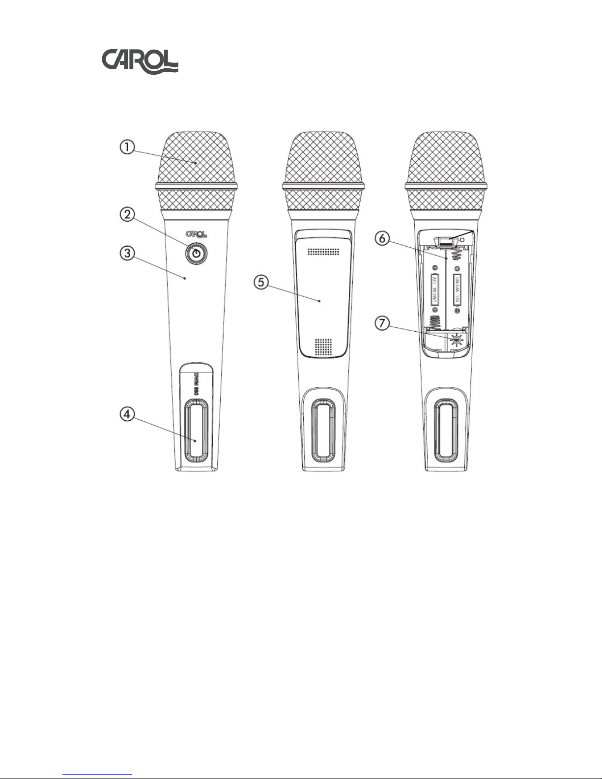
1.2 DWM-880 Digital Wireless Handle Microphone(Optional)
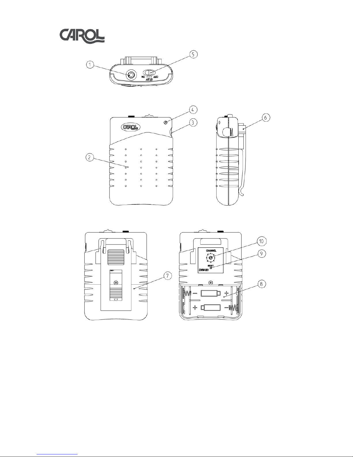
1.3 DWM-881 Bodypack Digital Wireless Transmitter(Optional)
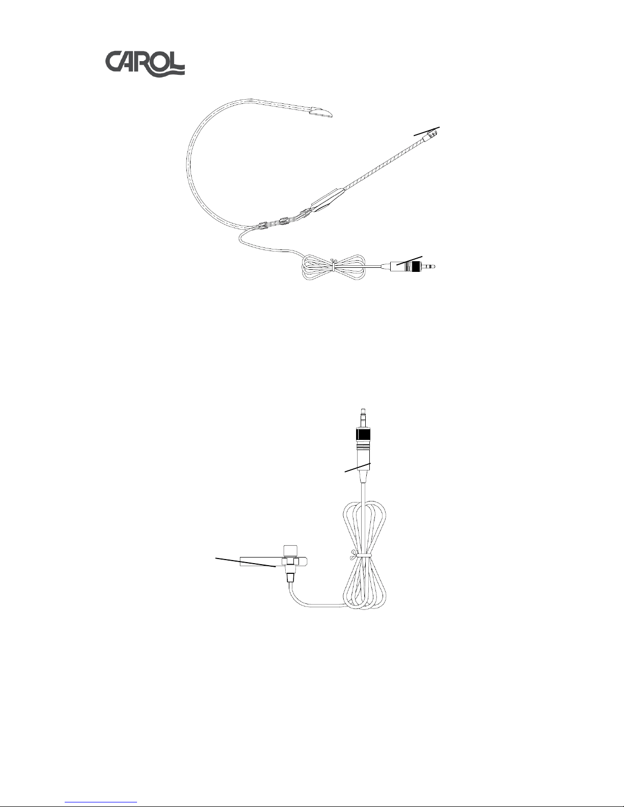
1.4 MUD-806 Headset Microphone (Optional)
1.5 MDM-863 Tie-clip Microphone (Optional)
1.6 DC 7.5V Power adapter
1.7 ø6.3mm M-XLR/M-XLR Cable
1.8 User’s Manual
2. Parts Identification and Function
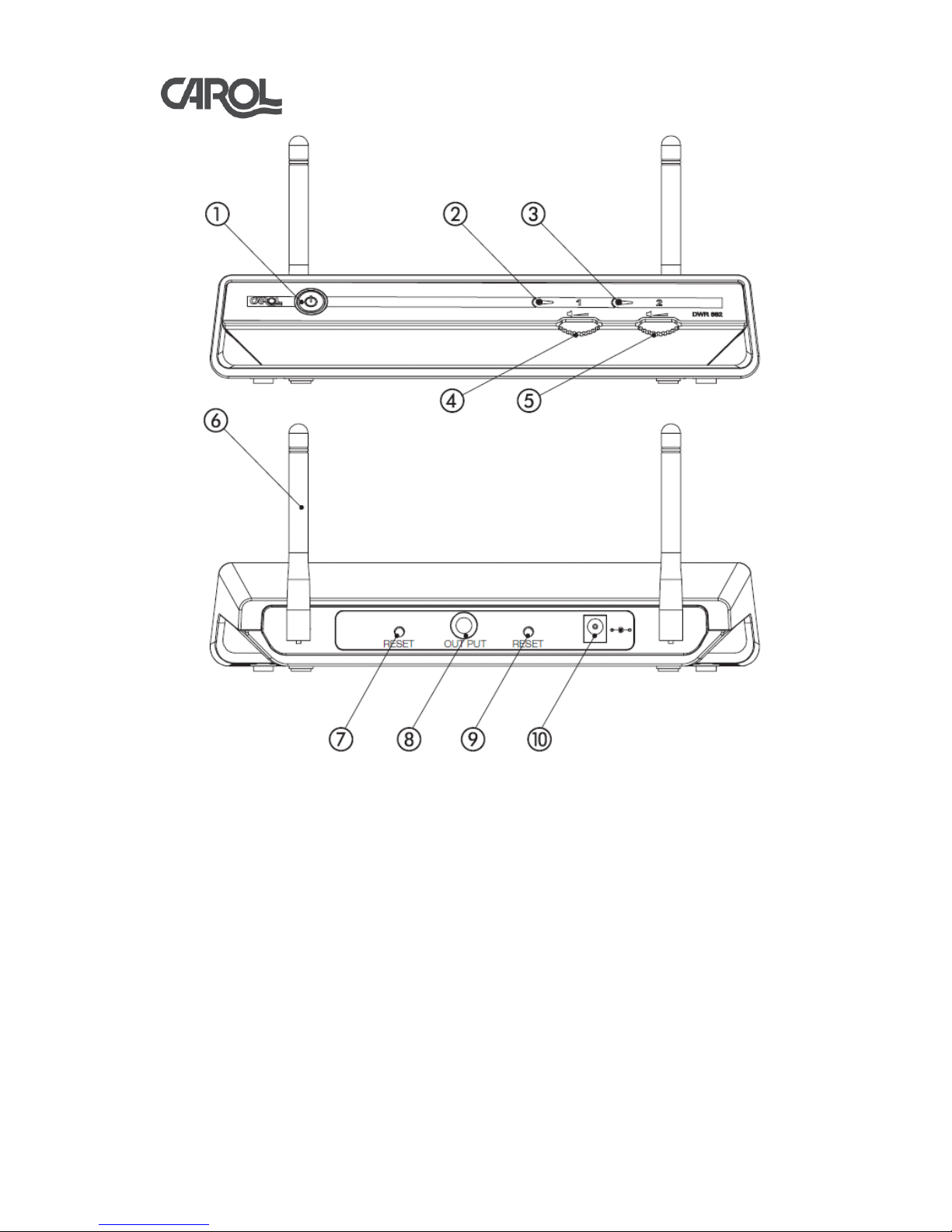
2.1 DWR-882 Digital Wireless Receiver (as shown in figure 2.1)
(1) POWER SWITCH: Switches on/off the Receiver (with status LED).
(2)MIC 1 CONNECTING LED: Lights up when microphone 1 is connected.
(3)MIC 2 CONNECTING LED: Lights up when microphone 2 is connected.
(4)VOLUME CONTROLLER 1: Controls the output volume of microphone 1.
(5)VOLUME CONTROLLER 2: Controls the output volume of microphone 2.
(6)ANTENNA: Receives signals from the microphone. The angle of the antennas
can be adjusted leftward, rightward or backward manually.
(7)RESET BUTTON 1: Resets microphone 1 (FOR TECHNICIANS USE ONLY).
(8)ø 6.3mm FEMALE JACK: Connects to the output of amplifier.
(9)RESET BUTTON 2: Resets microphone 2 (FOR TECHNICIANS USE ONLY).
(10)DC POWER RECEPTACLE: Connects DC adapter, and the polarity of central pole
is positive.
Digital Wireless Microphone User Manual
3
Figure 2.1
2.2 DWM-880 Digital Wireless Handle Microphones (as shown in figure 2.2)
(1)BALL GRILLE: Protects the capsule, and the enclosed windscreen can reduces pop
noises effectively.
(2)POWER SWITCH: Switches on/off the microphone (with status LED).
(3)HOUSING: For easy handling the microphone and protects the wireless transmitting
PCB inside.
(4)LOGO PLATE: Protects the antenna and strengthen the transmitting effect. Do not
cover this area while using.
(5)BATTERY COVER: Protects batteries and keeps them from falling off.
(6)BATTERY COMPARTMENT: Accommodates two AA batteries.
(7)CHANNEL SWITCH: Changes the channel (total 16 channels) to eliminate possible
interferences.
Digital Wireless Microphone User Manual
4
(8)RESET BUTTON: Resets the Transmitter signal (FOR TECHNICIANS USE ONLY).
Figure 2.2
2.3 DWM-881 Bodypack Digital Wireless Transmitter(as shown in figure 2.3 and 2.4)
(1)ø 3.5mm EARPHONE JACK: Connects head-worn or lapel condenser microphone.
(2) TRANSMITTER CASING: Protects the wireless transmission PCB inside.
(3)VOLUME CONTROLLER: Controls the output volume to avoid feedback/howling.
(4)POWER LED: The status LED will light up when power on.
(5)POWER SWITCH: Switches on/off the Transmitter’s power and mute mode.
(6)BELT-CLIP: For attaching the Transmitter to the user's clothing(eg. belt, waistband).
(7)BATTERY COVER: Protects batteries and keeps them from falling off.
(8)BATTERY COMPARTMENT: Accommodates two AA batteries.
(9)RESET BUTTON: Resets the Transmitter signal (FOR TECHNICIANS USE ONLY).
(10)CHANNEL SWITCH: Changes channels (total 16 channels) to eliminate possible
interferences.

Digital Wireless Microphone User Manual
5
Figure 2.3
Figure 2.4
2.4 MUD-806 Headset Microphone.(as shown in figure 2.5)
(1) ø 3.5mm STEREO PLUG: Connects Bodypack digital wireless transmitter.
(2) CONDENSER MICROPHONE: Uni-directional microphone capsule.
Digital Wireless Microphone User Manual
6
Figure 2.5
2.5 MDM-863 Tie-clip Microphone.(as shown in figure 2.6)
(1) CONDENSER MICROPHONE: Omni-directional microphone capsule.
(2) ø 3.5mm STEREO PLUG: Connects Bodypack digital wireless transmitter.
圖2.6
3. Receiver Operating Instruction
3.1 Plug the supplied DC adapter to a wall outlet, and then connect the DC adapter to
the power receptacle on Receiver.




Digital Wireless Microphone User Manual
7
3.2 Press the Receiver’s power switch to turn the power on, and the status LED will
light up green, it indicates the Receiver is on.
3.3 If a feedback noise appears when the volume is too high or the microphone is too
close to the speaker, turn the volume down.
4. Wireless Handheld Microphone Operating Instruction
4.1 Turning ON
4.1.1 Press the microphone’s power switch to turn the power on, and the status LED
will light up green. When the microphone connecting LED on the Receiver
lights up red, it indicates the microphone signal is been received by the
Receiver.
4.1.2 For best result, keep the microphone to the sound source in between 2 to 5 cm.
4.2 Turning OFF
Keep pressing the microphone power switch for 2 to 3 seconds till the status LED
goes off. When the microphone is been turned off, the microphone connecting LED
on the Receiver will also go off. Press the power switch on the Receiver till the
status LED goes off.
4.3 Replacing Batteries
4.3.1 When the status LED keeps blinking after the microphone is on, it indicates the
battery energy is running low, so please replace the batteries.
4.3.2 As shown in figure 4.1, press on where circle 1 indicates and push the battery
cover forward to the end, then remove the cover (CAUTION: To avoid injury,
do not place your fingers at where circle 2 indicates when pushing the cover).
Figure 4.1
4.3.3 Insert two AA batteries in the battery compartment according to the polarity
marks.
Figure 4.2
1
2
Digital Wireless Microphone User Manual
8
4.3.4 Close the battery cover. Place the cover on top front of the battery compartment,
then press on where circle 3 indicates and push the battery cover downward to
the end (CAUTION: To avoid injury, DO NOT place your fingers at where
circle 4 indicates when pushing the cover).
Figure 4.3
4.4 Change the Digital Wireless Microphone Channel
4.4.1 When using wireless microphone, there might be interferences from the signals
transmitted by another wireless microphone or other 2.4G wireless appliances
near by. These disturbances can be solved by selecting a different channel.
4.4.2 When changing the channel, it is not necessary to turn the power off. Open the
battery cover, and the channel switch is located next to the battery
compartment. There are 8 channel scales on the switch (as shown in the figure
4.4), and another 8 channels can be selected in between scales.
4.4.3 Fitting a slotted screwdriver into the slot, and rotate the switch clockwise or
counterclockwise to a desired channel. When a new channel is selected, the
microphone connecting LED on the Receiver will blink once, which indicates
the microphone and Receiver are reconnected.
4.4.4 To avoid interference and gain the best result, microphone 1 and 2 should be 8
channels apart. If not applicable, keep at least 2 channels apart.
3 4
Digital Wireless Microphone User Manual
9
Figure 4.4
5. Bodypack Wireless Transmitter Operating Instruction
5.1 Connect a head-worn or lapel condenser microphone to the ø3.5mm Earphone Jack
on the Transmitter.
5.2 Push the Power Switch on the Transmitter to ON as shown in figure 5.1, and the
Power LED will light up red, it indicates the Transmitter is on. When the
microphone connection status LED on the Receiver lights up red, it indicates the
Receiver has already picked up the signals from Microphone, so you can now talk
to the microphone.
Figure 5.1
5.3 If a feedback noise appears when the volume is too high or the microphone is too
close to the speaker, turn the volume down.
5.4 When mute is needed, push the Power Switch on the Transmitter to ST.BY position
as shown in figure 5.2. To unmute the audio signal, simply push the Power Switch
back to ON position.
Power Switch, push to ON
Power Switch, push to ST.BY
Fit the slotted
screwdriver into
this slot.
When selecting
the channel, aim
the arrow at the
scale or in
between two
scales.
Digital Wireless Microphone User Manual
10
Figure 5.2
5.5 Push the Power Switch on the Transmitter to OFF as shown in figure 3.3, and the
Power LED will go off, so as the red light on the Receiver’s microphone connection
status LED.
Figure 5.3
5.6 Replacing Batteries
5.6.1 When the status LED keeps blinking red after the microphone is on, it indicates
the battery energy is running low, so please replace the batteries.
5.6.2 First step is to remove the Belt-Clip. As shown in figure 5.4, press on where
circle 1 and 2 indicates to remove Belt-Clip.
Figure 5.4
Power Switch, push to OFF
1 2