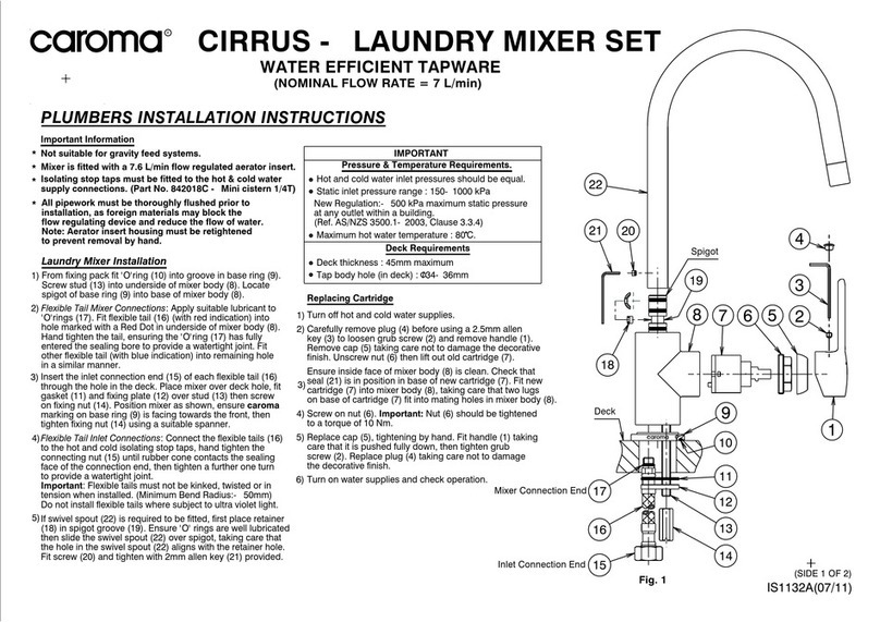
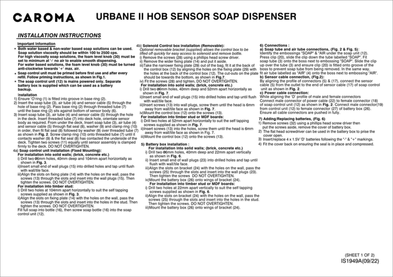
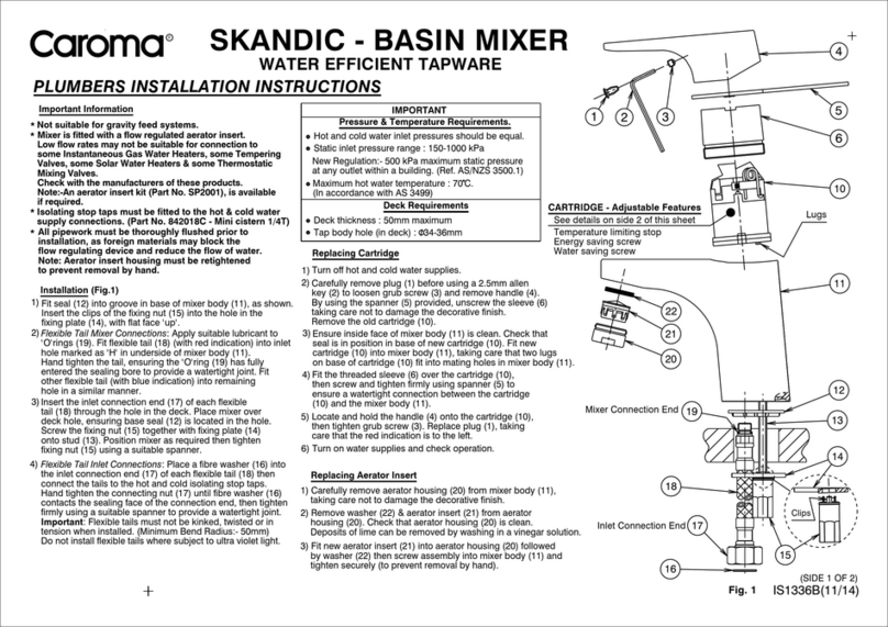
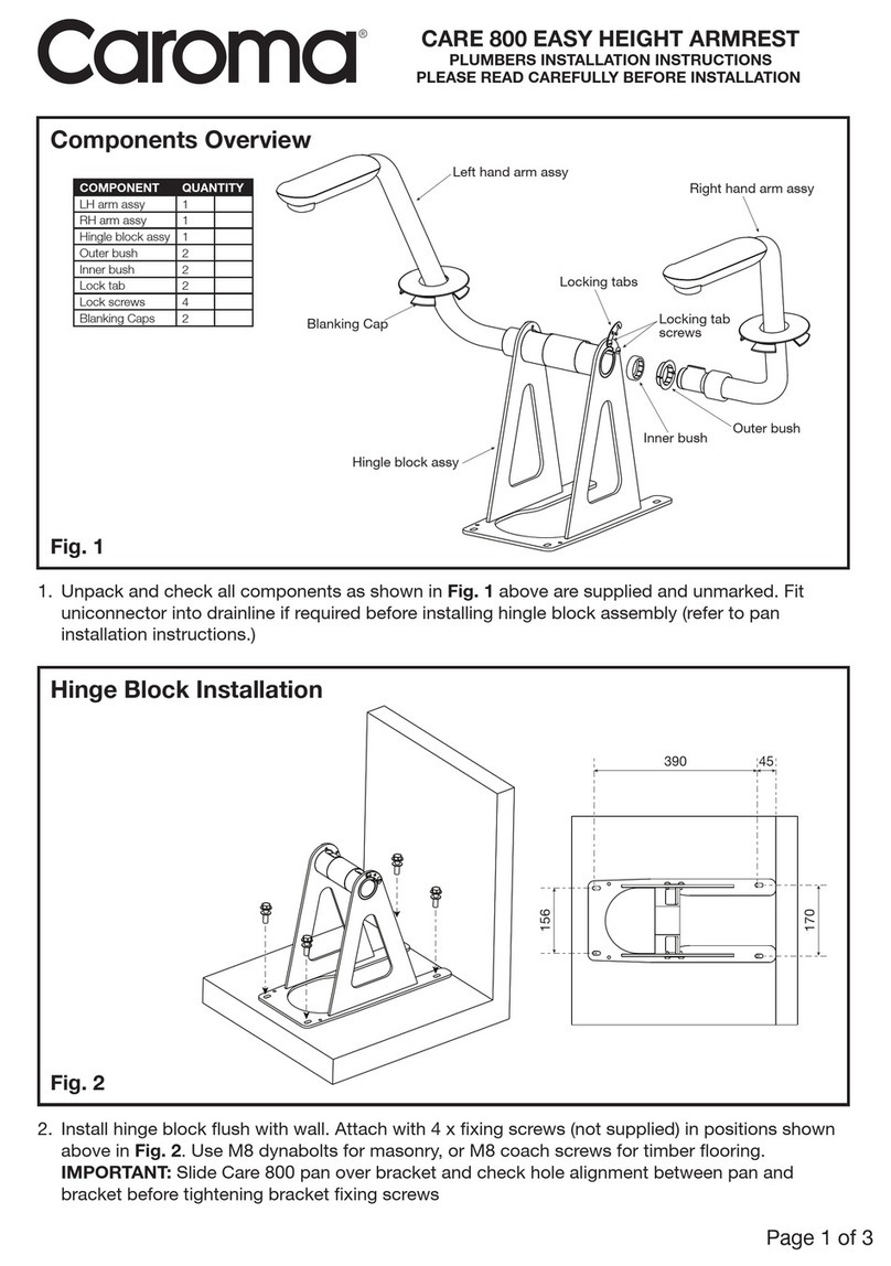
7
1. Checkthatthe4"(100mm)soilpipeis
centredbetweenthestuds-checkthere
is15.75"-16.5"(400-420mm)between
thestuds(17.7"or450mm nominal to
studcentres).
2. Calculatethenishedoorheight
(allowingforoorgradingsandtilethick-
ness,etc.)andaddthistotheknown
heightoftheselectedbowl'sinlet.Mark
this resulting height on the stud - This
is your “Datum A” and ush pipe
centre line.
NOTE: This is your “Datum A” and
ush pipe centre line. From nished
oor to centre of waste pipe is 8 ¼".
From nished oor to centre of
ushpipe is 14 ½"to achieve 17"seat
height. See diagram on page 6.
3. Measure and ensure the Flush Pipe
Centre Line which is marked on the Bowl
Bracket is at the correct height. This
should match the Datum A previously
established.Useanallenkeytoadjust.
Ensureboltsaretightenedaftersetting.
4. Placethebowlbracket&tankas-
semblyinpositionandmarkoutall4bolt
locationsinthebracketfeet.
NOTE: The front face of the bowl
bracket should be ush with the front
face of the studs (“Datum B”) & the 4"
(100mm) soil pipe should be centred
in both the wall cavity and between
studs as well as being cut ush with
the oor. (Depending on code approv-
als in your area: if it is 4"then the
insert tting is used and it is cut ush.
If the connection is 3" it is below the
oor and the supplied waste pipe is
long enough to go through the oor).
9. Screw in threaded rods for mounting the
bowlandlockinpositionwithnutsagainst
the Front Plate.
Three hole spacings are provided:
1-7.9”or200mm.UseHole#1forWalvitBowls.
2-11”or280mm.
3-7”or180mm.UseHole#3forCubeBowls.
10. Screw the tank in place using at least
1 of the 2 holes provided in the top of each
mountingbracket.Makesurethewatercon-
nectionttingisonthelefthandsideoftank
andtankisushwithwall.
11. Connect the water supply with 15/16
14NS-1ttingandadaptorttingfor1/2"
bothsupplied.
12. RemoveDustCover,turnIsolatingTap
ON,lltank&setwaterlevelusingAdjust-
ing Screw on the inlet valve.
13. Check tank and all joints for leaks.
14. Turn Isolating Tap OFF. Continue with
Preparation for Fitout on page 12.
5. MoveBowlBracket&TankAssembly
out of its installation position and drill the 4
holesintheoorasmarked.Carriermust
beanchoredsecurelytotheoor.
For Structural Flooring (concrete)
Drill Ø0.5"or12mmholeforusewithM12
TRU Bolts supplied in pack.
For Non Structural Flooring (wood)
Drilltosuitxingsused(xingsnotsup-
plied).Theverticalarmsofthebowl
bracketmustalsobeboltedtosidestuds.
6. LubricatetheWastePipewithsoapand
water and push into the soil pipe. Carefully
repositionBowlBracket&TankAssembly
andsecurewithxings(orusemechanical
joint coupler provided this method meets
withlocalcoderequirements).Adddimen-
sions to diagram as shown.
7. Slide the Waste Pipe up so the
centrelinemarkedonthebodyissetat
thecorrectspacingfromtheushpipe
Datum A.
8. SecuretheWastePipepositionby
rmlypushingtheWastePipeClips
outwards to latch on to the threaded rods.
