R
(SIDE 1 OF 2)
IS1336B(11/14)
17
15
14
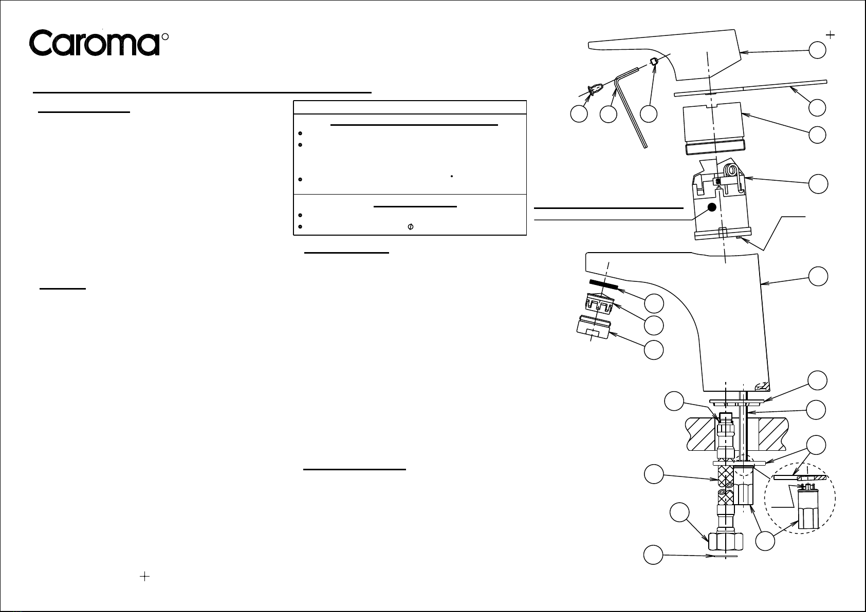
Fig. 1
Mixer Connection End
18
Inlet Connection End
19
4
3
6
10
11
12
22
20
21
12
13
Lugs
Clips
16
5
CARTRIDGE - Adjustable Features
See details on side 2 of this sheet
Temperature limiting stop
Energy saving screw
Water saving screw
SKANDIC - BASIN MIXER
WATER EFFICIENT TAPWARE
Important Information
*Not suitable for gravity feed systems.
*
*
*All pipework must be thoroughly flushed prior to
installation, as foreign materials may block the
flow regulating device and reduce the flow of water.
Note: Aerator insert housing must be retightened
to prevent removal by hand.
Mixer is fitted with a flow regulated aerator insert.
Low flow rates may not be suitable for connection to
some Instantaneous Gas Water Heaters, some Tempering
Valves, some Solar Water Heaters & some Thermostatic
Mixing Valves.
Check with the manufacturers of these products.
Note:-An aerator insert kit (Part No. SP2001), is available
if required.
Isolating stop taps must be fitted to the hot & cold water
supply connections. (Part No. 842018C - Mini cistern 1/4T)
1) Fit seal (12) into groove in base of mixer body (11), as shown.
Insert the clips of the fixing nut (15) into the hole in the
fixing plate (14), with flat face 'up'.
Installation (Fig.1)
2)
3)
4)
Flexible Tail Mixer Connections: Apply suitable lubricant to
'O'rings (19). Fit flexible tail (18) (with red indication) into inlet
hole marked as 'H' in underside of mixer body (11).
Hand tighten the tail, ensuring the 'O'ring (19) has fully
entered the sealing bore to provide a watertight joint. Fit
other flexible tail (with blue indication) into remaining
hole in a similar manner.
Insert the inlet connection end (17) of each flexible
tail (18) through the hole in the deck. Place mixer over
deck hole, ensuring base seal (12) is located in the hole.
Screw the fixing nut (15) together with fixing plate (14)
onto stud (13). Position mixer as required then tighten
fixing nut (15) using a suitable spanner.
Flexible Tail Inlet Connections: Place a fibre washer (16) into
the inlet connection end (17) of each flexible tail (18) then
connect the tails to the hot and cold isolating stop taps.
Hand tighten the connecting nut (17) until fibre washer (16)
contacts the sealing face of the connection end, then tighten
firmly using a suitable spanner to provide a watertight joint.
Important: Flexible tails must not be kinked, twisted or in
tension when installed. (Minimum Bend Radius:- 50mm)
Do not install flexible tails where subject to ultra violet light.
PLUMBERS INSTALLATION INSTRUCTIONS
Replacing Aerator Insert
1) Carefully remove aerator housing (20) from mixer body (11),
taking care not to damage the decorative finish.
2) Remove washer (22) & aerator insert (21) from aerator
housing (20). Check that aerator housing (20) is clean.
Deposits of lime can be removed by washing in a vinegar solution.
3) Fit new aerator insert (21) into aerator housing (20) followed
by washer (22) then screw assembly into mixer body (11) and
tighten securely (to prevent removal by hand).
Replacing Cartridge
Turn off hot and cold water supplies.
Carefully remove plug (1) before using a 2.5mm allen
key (2) to loosen grub screw (3) and remove handle (4).
By using the spanner (5) provided, unscrew the sleeve (6)
taking care not to damage the decorative finish.
Remove the old cartridge (10).
Ensure inside face of mixer body (11) is clean. Check that
seal is in position in base of new cartridge (10). Fit new
cartridge (10) into mixer body (11), taking care that two lugs
on base of cartridge (10) fit into mating holes in mixer body (11).
Fit the threaded sleeve (6) over the cartridge (10),
then screw and tighten firmly using spanner (5) to
ensure a watertight connection between the cartridge
(10) and the mixer body (11).
Locate and hold the handle (4) onto the cartridge (10),
then tighten grub screw (3). Replace plug (1), taking
care that the red indication is to the left.
Turn on water supplies and check operation.
1)
2)
3)
4)
5)
6)
Hot and cold water inlet pressures should be equal.
Static inlet pressure range : 150-1000 kPa
IMPORTANT
Pressure & Temperature Requirements.
Deck thickness : 50mm maximum
Deck Requirements
Maximum hot water temperature : 70 C.
(In accordance with AS 3499)
Tap body hole (in deck) : 34-36mm
New Regulation:- 500 kPa maximum static pressure
at any outlet within a building. (Ref. AS/NZS 3500.1)


